Electronics Production
WEEK 04
(18/02/2021 12:15 p.m.) It's Thursday morning. It's a new day after a hard Wednesday I had.
Chan, chan, chan! (dramatic sound).
But, as always, the next day our superheroes and local instructors from Fab Lab Leon came to our rescue! 💖
Nuria explained us which were the guides that we had to follow to make, solder and program our first PCBs, and just as, she gave us some small guides on how to use the multimeter and how to place the components that have polarity in the circuit. 🙂🙃
Last year, I was able to get my first taste of circuits, using the Arduino and soldering. But, this is the first time that I make, program my own PCBs and solder such tiny components. I'm scared! 😅😰
But I stay positive! As Adrián says us: "Soldering is like dancing!" 1,2,3,4 ... 1,2,3,4 ... 1,2,3,4 ... So, let's dance this week!💃🕺
The good thing about this week is, during Friday and Saturday, I was able to meet in person two other of my friends and adventure crewmates companions, Mauro and Sergio.
I could only see Mauro briefly (to do component traffic tss!🤫). But with Sergio, Alberto and I had the opportunity to spend whole Saturday with him in the Fab lab UE, soldering and programming. He brought us gifts from Adrián + Nuria + Pablo 💚💚💚 and he helped us a lot!. Mickael is the last crewmate I have to meet, in addition to my instructors, who I am looking forward to seeing in person 😢.
As this week we start good Rock and Roll, this week's song is Stop When the Red Lights Flash by Green Day. FabISP: I´ll make you surrender!💪
NOTE: Although this week's song began with the discography of "¡Uno!, ¡Dos!, ¡Tré!" from Green Day, my instructors and crewmates know that the song of the week is actually: "Soy un gnomo", from my childhood cartoons series "David, the Gnome". 🤣🤣
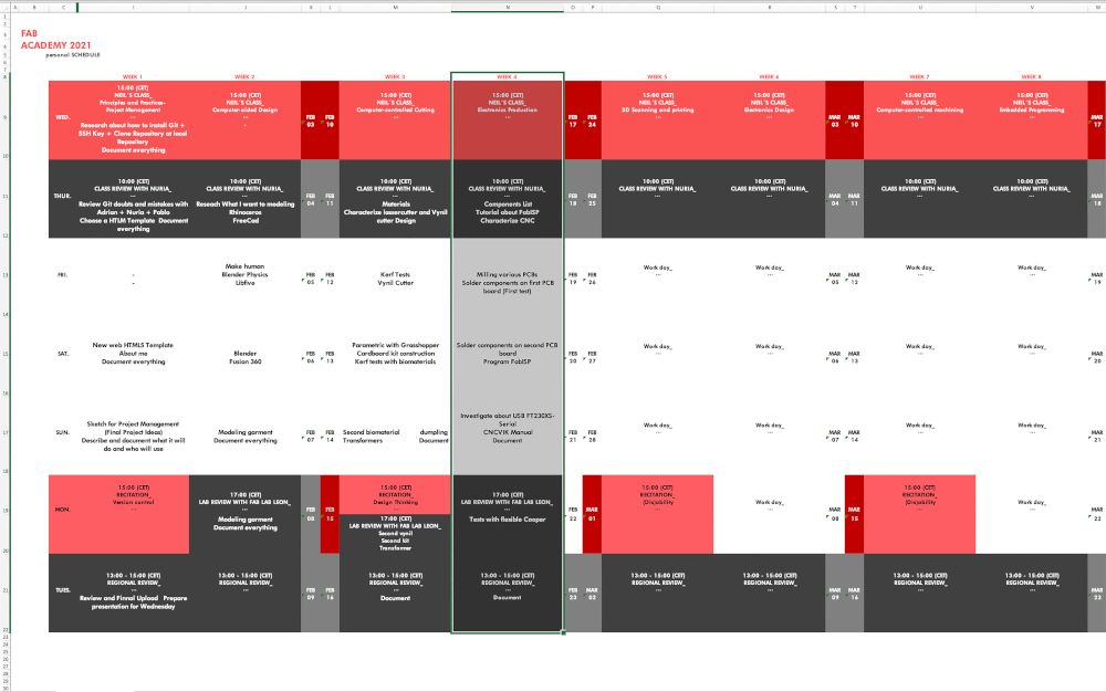
Organizing tasks
Like last week, we have two types of assignments, one's group and other individual., so as usual, I organize my schedule and here the following Evaluation Criteria that we have to approach to complete the Assignment:
- ✓ Characterize the design rules for our PCB production process: document feeds, speeds, plunge rate, depth of cut (traces and outline) and tooling
- ✓ Document our work with the CNC machine
- ✓ Upload our original design files
- ✓ Make an in-circuit programmer by milling and stuffing the PCB and test it
- ✓ Document how you made (mill, stuff, solder) the PCB ans if it is funcional
- ✓ Document mistakes and possible obstacles encountered in the process
- ✓ Optionally, try other PCB fabrication process
- ✓ Include a "hero shot" with our board
- Model: Roland SRM-20
- Software: Fab Modules + Roland VPanel for SRM-20
- Work Area: 232x156,6 mm
- Revolution Speed: 3000-7000 rpm
- Mechanical Resolution: 0.000998584 mm/step
- Material to work: FR1 Printed Circuit Board 70x100 mm
- Tools:
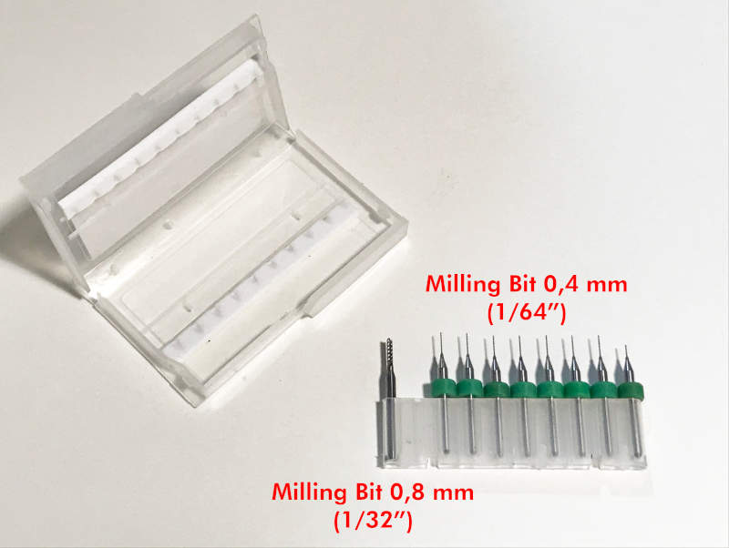
- Milling Bit 0,4 mm (1/64")
- Milling Bit 0,8 mm (1/32")
- Milling Bit 0,4 mm (1/64"). To mill the "tracks" or pockets
- Milling Bit 0,8 mm (1/32"). To cut the perimeter of the PBC boards
- FAB MODULES
- MILLING THE PCB BOARD
- SOLDERING FabTinyISP COMPONENTS
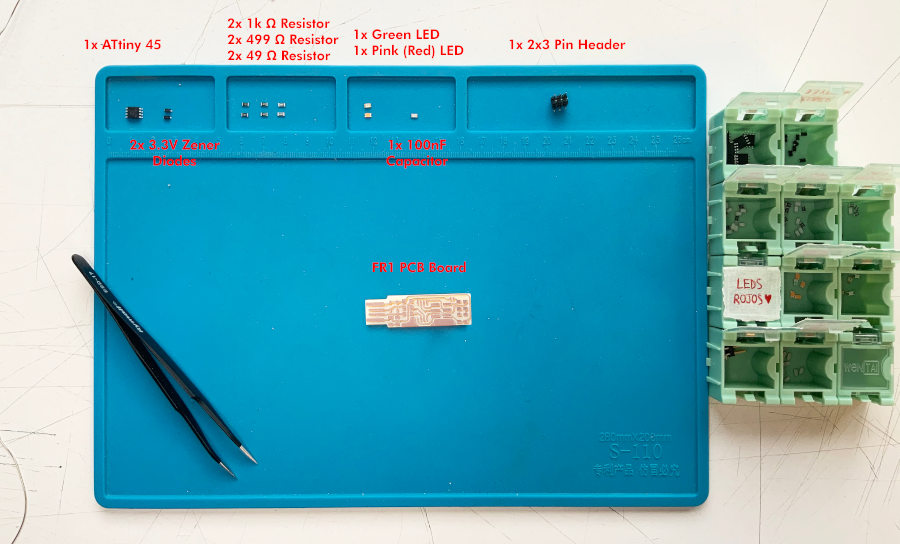
- 1x ATtiny45
- 2x 1kΩ resistors
- 2x 499Ω resistors
- 2x 49Ω resistors
- 2x 3.3v zener diodes
- 1x red LED (In my case, I have replaced the red LED with some pink LEDs that my crewmate Sergio has brought me from Leon on behalf of Adrián + Nuria + Pablo 😍💗)
- 1x green LED
- 1x 100nF capacitor
- 1x 2x3 pin header
- PROGRAMMING MY FabTinyISP BOARD
- Xcode (FROM App Store)
- Command Line Tools (the latest version available)
- CrossPack (the latest version available too)
- 1st. The programmer FabATtiny with our computer through an adapter or USB cable.
- 2nd. The programmer with my FabATtiny to program.
- 3rd. My FabATtiny with another power source (be it another computer or a plug) through a other USB cable and/or a mobile charger.
- brew install avrdude
- brew reinstall avrdude
- brew tap osx-cross/avr && brew install avr-gcc
- brew update
- sudo avrdude -c usbtiny -p t45
- sudo avrdude -c usbtiny -p t45 -V -U lfuse:w:0xe1:m -U hfuse:w:0xdd:m -U efuse:w:0xff:m
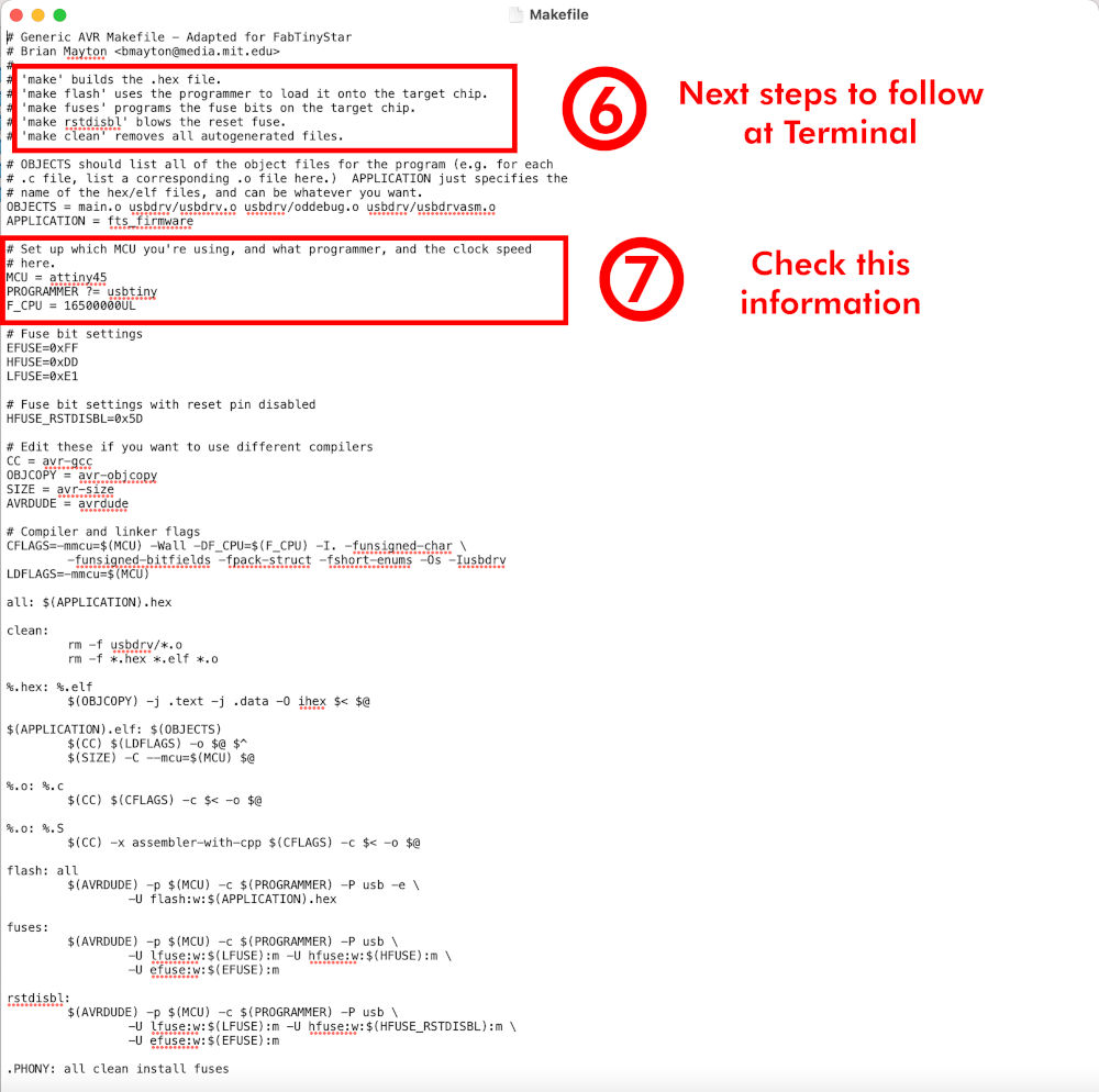
- MCU = attiny45
- PROGRAMMER ?= usbtiny
- F_CPU = 16500000UL
- cd fts_firmware_bdm_v1
- sudo make install
- sudo make clean
- sudo make
- sudo make flash
- sudo make fuses
- sudo make rstdisbl
- One, it could be it had made some mistake during the makes, and when launching the last step make rstdisbl is irreversible, and can no longer be reprogrammed.
- Other, it may be that having a faulty track is a short circuit and when I did make rstdisbl it was not work"
- Another may be that one of the components is poorly soldering or loose, so you would have to re-weld all the components.
- -It could be the board is smaller than the original size, it cannot connect well and has been disabled.
- ...
- PCBs with SRM-20
- Introduction to Mods (Spanish)
- Roland MDX-20 with Mods (Spanish)
- FabAtinyISP Tutorial
- Programming FabAtinyISP. Nuria´s Tutorial (spanglish)
- Harm Vanvugt (Electronic Production Assignment)
- "Woma" (Electronic Production Assignment)
Individual assignment
Extra credit
First of all, for each Fab Academy assignments, especially those related to electronics, it is very important to carry out the components inventory of the fab lab. As a future member of the fab lab IED Madrid, it is my responsibility to keep the electronics inventory up to date. I have to take care of updating list of new components, replacing obsolete one´s, and checking that I always have enough components for future use.
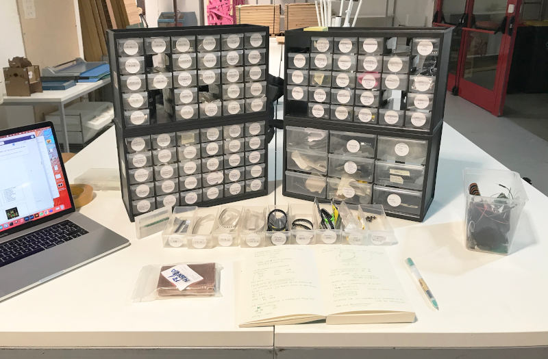
(23/02/2021 12:32 p.m). As a reminder and I explained in the first assignment, to facilitate better communication on this and future assignments, I'm going to tip out the correct process in black, failures and errors in purple, and my internal thoughts and comments in orange. In the different paragraphs you are going to see different jumps in time, so you can located on my common mistakes during the process.
Group Assignment
THE CNC MACHINE AND THE PCB PRODUCTION PROCESS
At Fab Lab IED Madrid we have one CNC machine to produce PCB boards:
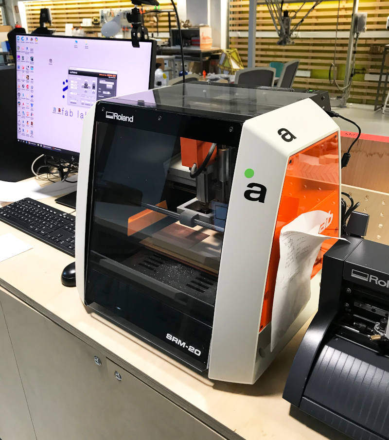
(18/02/2021 17:20 p.m). This is the first time I have used the small CNC machine for milling. So I had to need a lot of help from the directors and technicians of the fab lab to explain and verify the work I was doing. Thanks for each one!😅
We usually use the small CNC machine to mill PCB boards for Digital Fabrication electronics. To mill them we usually use Cut2D software and the parameters described in this sheet of paper. But in this occasion I am going to try other softwares for milling.
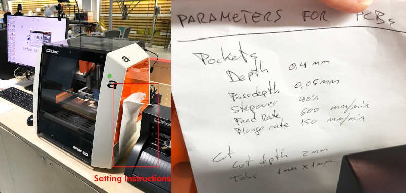
First of all, we are going to prepare and characterize the type of milling bits that we have to use. To make the PCB boards we have:
Inside the machine, we have a wooden tray, where we must stick our well-sealed PCB board with double-sided tape over the surface of the board.
We have to verify the plate is well sealed to the tray and always be generous with the double-sided tape over the whole FR1 board, otherwise a vibrational effect will be produced and could generate imperfections on our work.
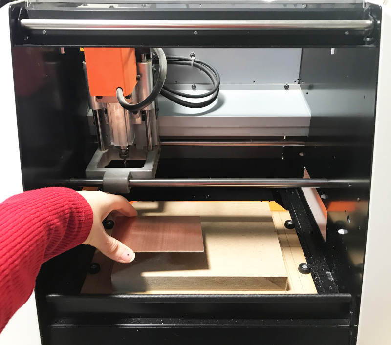
When we have our board in the right place and well glued, we have to calibrate the XYZ origin of our machine to start milling. We open the VPanel software. Within the program, with the arrows of -X+X, -Y+Y and -Z+Z we can move the milling machine around the workspace.
On Cursor Step section we have different forms of movement: ( Continue = Rapid movement); (x100 = Offset from cm to cm); (x10 = Offset from mm to mm); (x1 = Offset from dmm to dmm).
To begin we are going to calibrate the point of origin on XY. Once we have positioned the mill in the place we want, click on Set Origin Point X/Y.
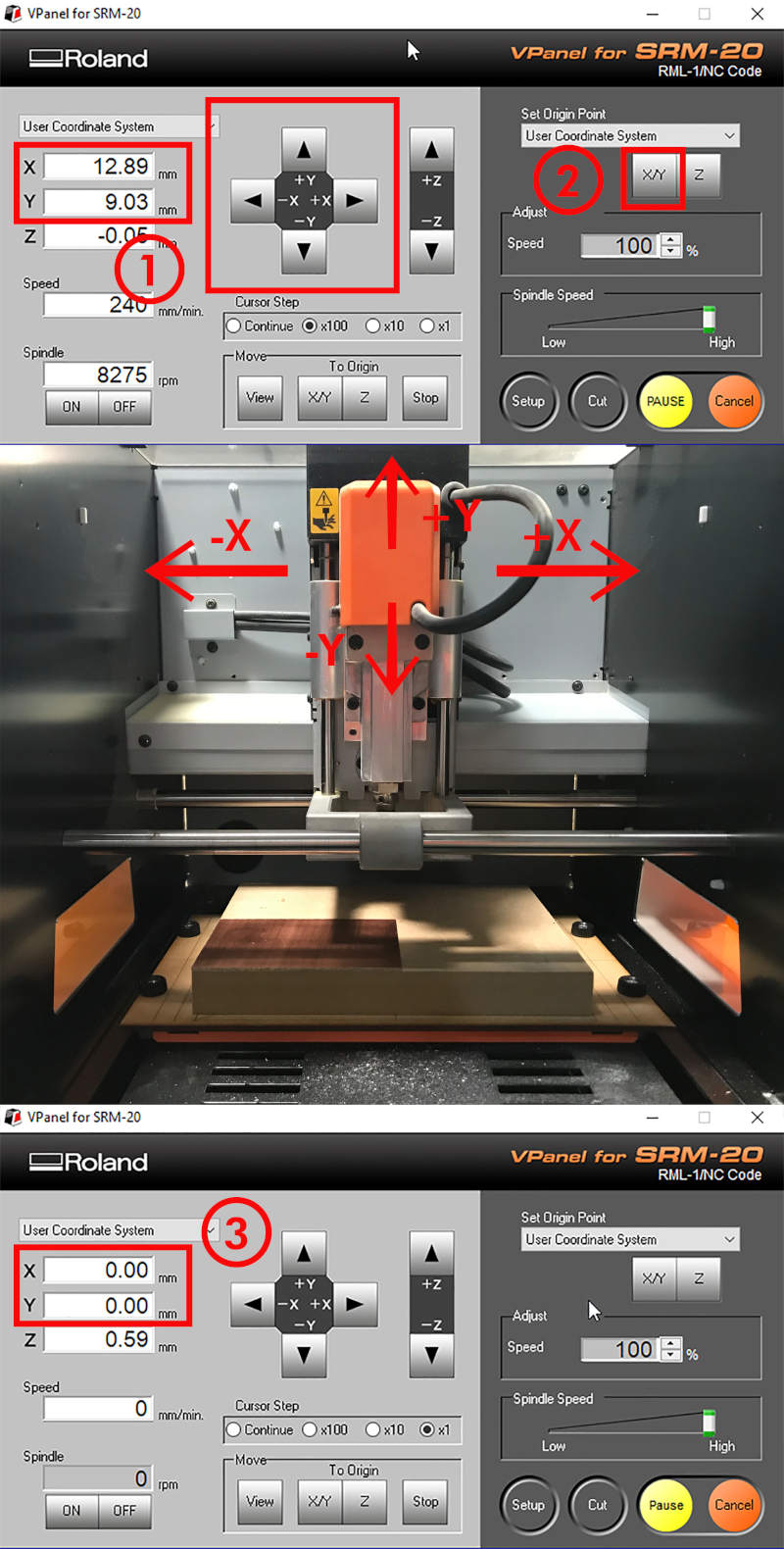
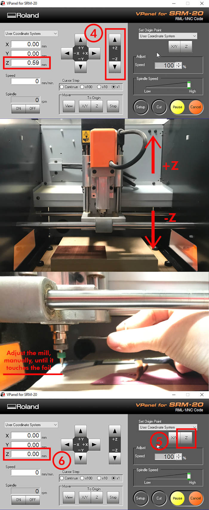
To calibrate the origin on Z, we use the arrows +Z-Z (with the milling bit that we are going to use in place). Be careful when moving in Z-space. In order to set the Z origin we have to locate the head of the milling bit flush with the exterior surface of the board.
It is recommended when we are approaching the board we begin to use the Cursor Step options to calibrate with greater precision.
(TIP: When we are reaching the desired position, place a sheet of paper between the board and the head of the milling bit, release the milling bit a little and let it fall on the sheet of paper. This will be the minimum optimal distance between plate and milling bit).
Once we have positioned the mill on the right Z position, click on Set Origin Point Z.
FAB MODULES vs MODS
To start milling we are going to use the Line test design to calibrate the speeds and adjustments necessary to make the future "rails" of our boards well.
There are several softwares which to be able to mill boards, but this week we are going to compare two types: Fab modules and Mods.

Following the PCB with SRM-20 tutorial, I have started using Fab Modules to mill the initial Line Tests. It is an online software allows you to load different types of design files and prepare them for milling or cutting in different types of machines. In our case, I am going to use some png images (in black and white) and I am going to program them to mill in the roland for mill the PCB outline.
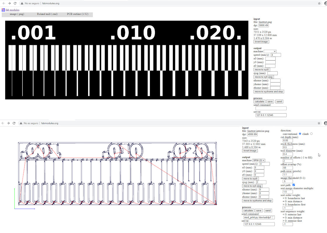
Once the parameters are set in the program, I Calculate the trajectory, Save it and send it to be cut by VPanel by pressing the function Cut> Add> Output.
Here you can see a small video, cutting the Line Test:
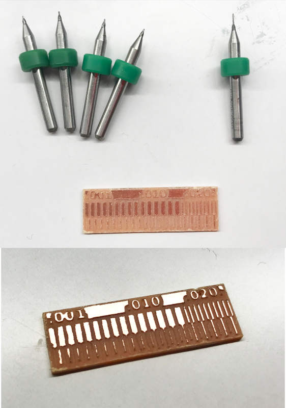
(18/02/2021 21:47 p.m). My first experience with Fab Modules was a bit of a mess 😅😫. The program calculates Speed with a different range than we did in the fab lab with Cut2D, and it took me several hours to understand most of the program's options and also wasted material too.
On the other hand, the FR1 boards I'm using are made of wood instead of phenolic paper, which cost me four broken milling bits and a less perfect finish 🙁.
Individual Assignment
FabTinyISP
To make the board we follow Brian´s FabATtiny 45 tutorial, and we use the png boards to mill it on the machine.

As I have anticipated before, to mill the first FabTiny board I have used Fab modules adjusting, a little, the parameters used on the Line Tests of the previous day.
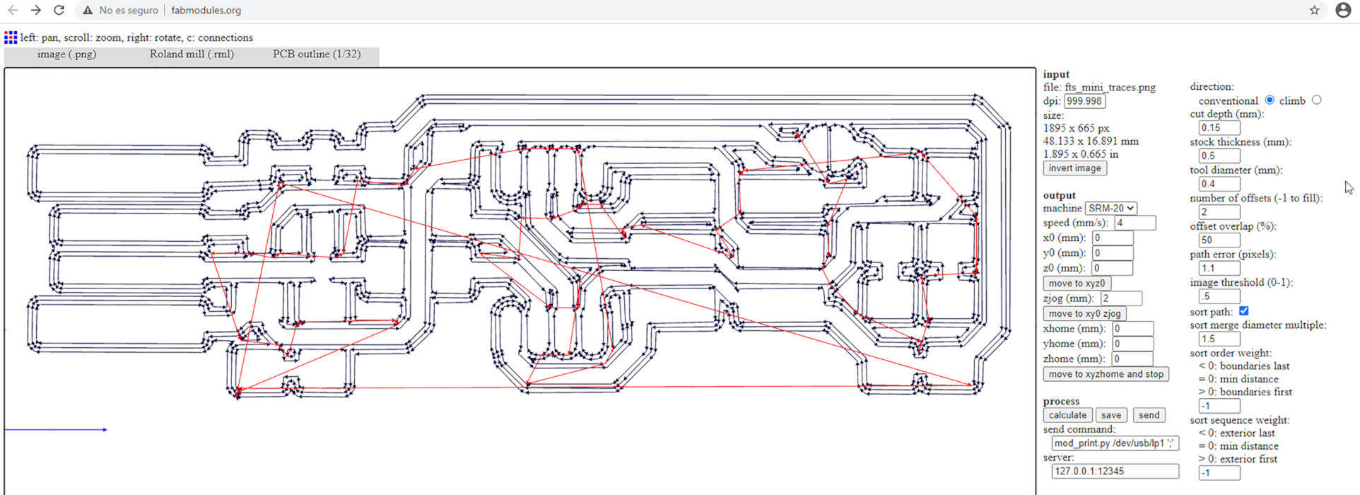
(18/02/2021 17:23 p.m.). Mysteriously, it seems that it has come out the first time! 🤣Here you can see another short video, where the machine is cutting the outer perimeter of the board:
Luckily, we found a board of phenolic paper at the fab lab! 🎉 And I decided to try to launch another FabTiny board with the same parameters that I used with the first board, to see if the problem could be the quality of the FR1 boards I was using.
While I was milling the second board, I decided to use the first one to learn how to solder the components. It was a bit difficult for me, especially for bad pulse I have 😤, but little by little I got him to practice and I started to like it. 🙂🙃
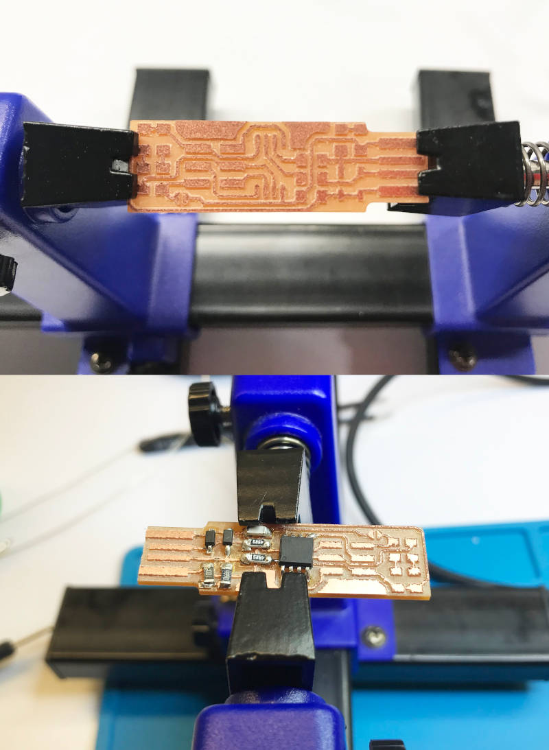
When I sent the second plate for milling, the 0.4 mm milling bit broke 🤬 and I had to change it and re-mill the file. Finally, although it took about two hours to grind and cut, this was the result!.
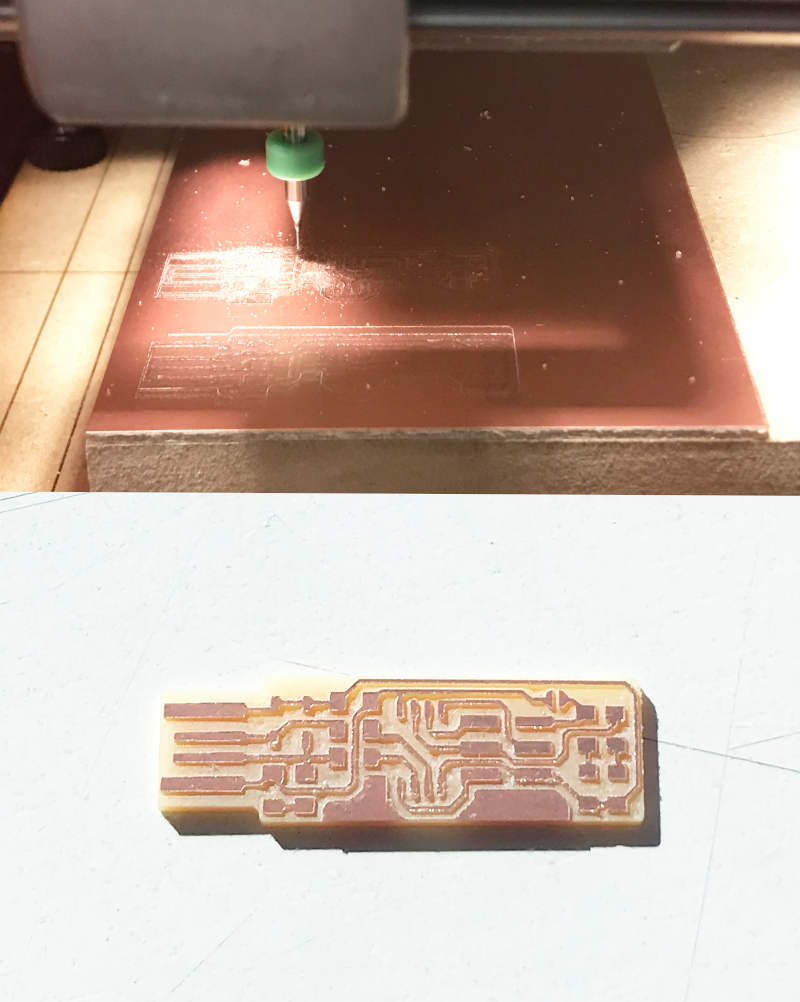
The finishing of this board was much more successful 🎉🎉 than with the wooden PCB board. It is possible the quality of the first one may not be very good, so I'll try to keep phenolic paper boards on hand in the future.
To solder the components on the first and second board, I had the electrical and graphic diagram, at hand, to locate the components correctly and take special care to place the components with polarity (LEDs, ATtiny 45 and the Zener Diodes).
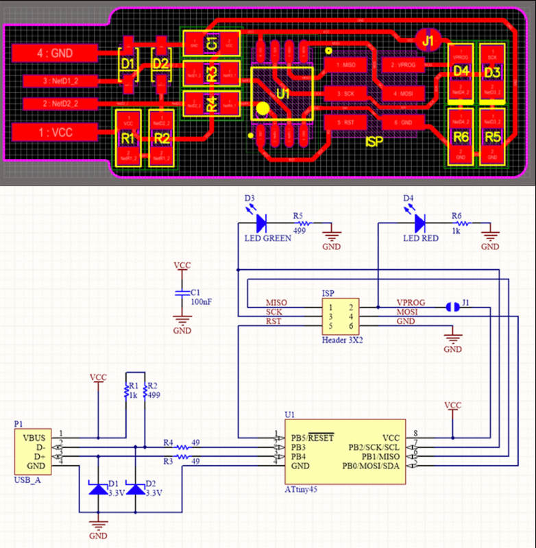
To compose the FabTinyISP we need:
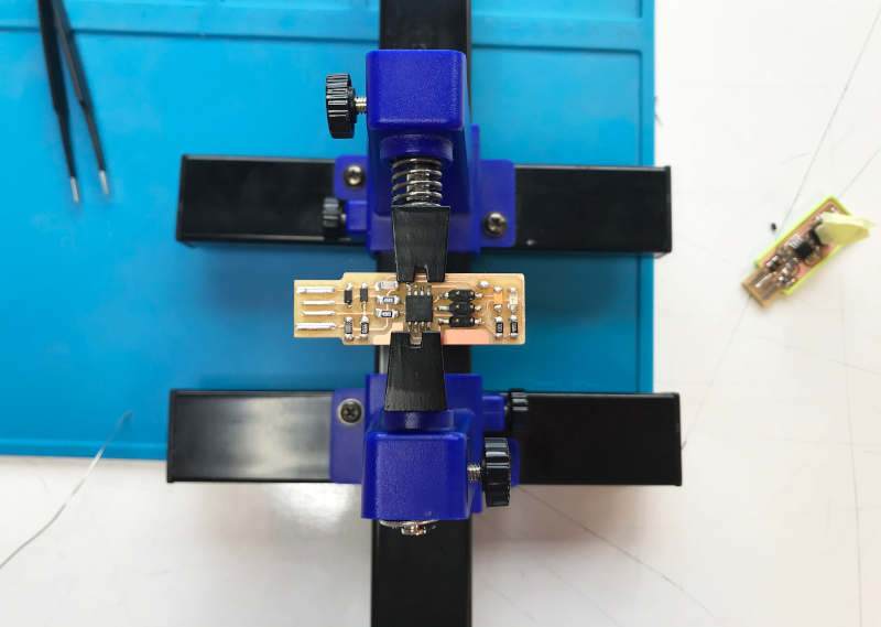
My second attempt with soldering was (more or less) along the lines of the first attempt. I made a few mistakes soldering ATtiny 45 legs together 😅. But luckily I was able to repair it with the desoldering and soldering iron handy. 💪💪
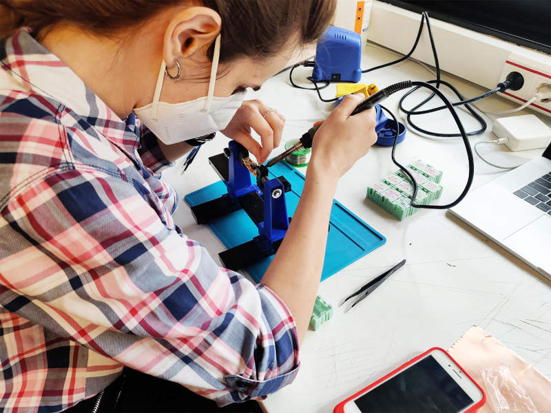
(19/02/2021 12:18 p.m.) During Saturday, I returned to Fab Lab UE with Alberto and Sergio 🤩, our other crewmate who is doing the Fab Academy presential in Leon, and with whom we had the opportunity to work and have a good time together.
In this time-lapse, you can see the three of us working and helping each other while I am soldering:
After spending most of Saturday morning soldering 🤣, this was the end result. It wasn't as perfect as it could be, but for the second board I soldered in my life, it was a good start.
At the background, you can see the FabATtiny of our instructor, Nuria, who Sergio brought us from Leon so that we could program our FabISP. Thank so much Nuria and Sergio! 😘
(19/02/2021 16:27 p.m.) On Saturday afternoon, while Alberto, Sergio and me were in the Global Open Time with our instructors Adrián and Pablo 😎😎, I began to program the FabATtinyISP board 👐.
To better understand the storytelling, first I will describe the right way which I could program my FabATtinyISP board with my Mac OS. And, at the end, I will count the mistakes made at the sections "Mistakes you can make or may arise in your Mac OS" 😅 and "More mistakes. Trying to program my first PCB board with my second PCB board" 😅😅
From the beginning, I have to thank very much to Sergio and Nuria 💖 for their help on this part of the process. As I mentioned before, electronics is my Achilles heel 🙃, and without them my experience would probably have been more disastrous.
To start with, we have to verify or install three developers:

To check if my FabATtiny is working correctly, I have connected Nuria's FabISP (programmer) with my FabISP (to program) on the same USB adapter. And we see that both work!
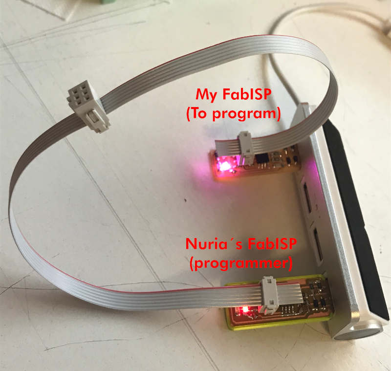
To start programming (and not damage the computer at the possibility unforeseen event with both FabATtiny) you must connect:
At first, we did not have a USB connection cable, and Alberto found among a pile of cables in his fab lab, a connection cable that had been manipulated by someone before 😵. Sergio and me, before plugging it into a charger, tested the cable connectivity on the adapter. When we saw the cable it worked, I placed it in its correct position.
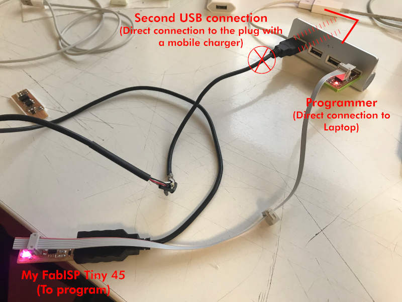
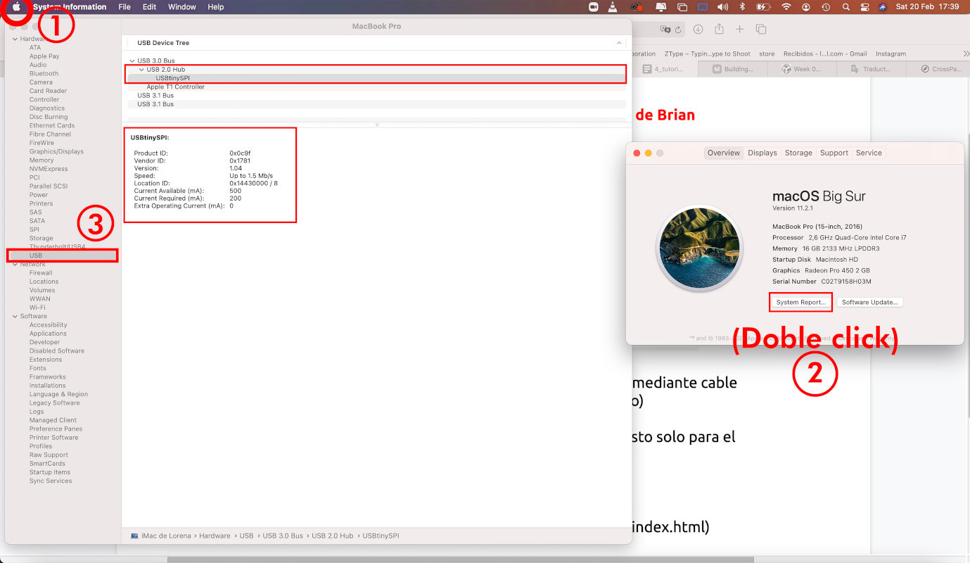
Once both FabATtiny are connected, we are going to check that our computer is reading the mother programmer (Nuria's FabATtiny). We go to:
Apple Icon (click) > About this Mac > (Overview) System report ...> USB > USB 2.0 hub > USBtinySPI
Clicking on the USBtiny will bring up some characteristics from the programmer that I will have to review on my FabATtiny when it is programmed.
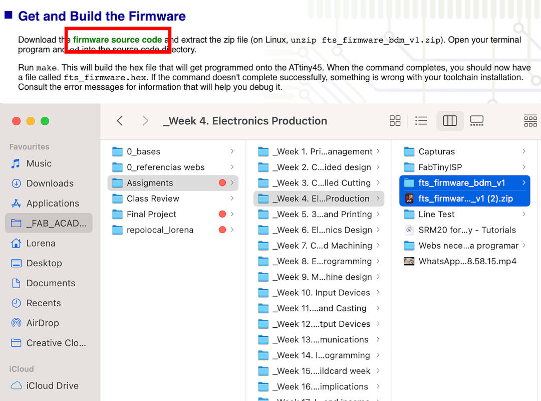
Then, following this part of Brian´s FabATtiny 45 tutorial, we download the compressed folder of the firmware source code (preferably, it is better to download the compressed folder from Google Chrome or Firefox) and locate it where we are going to program it. In my case, I have put it in my local "Electronics Production" folder.
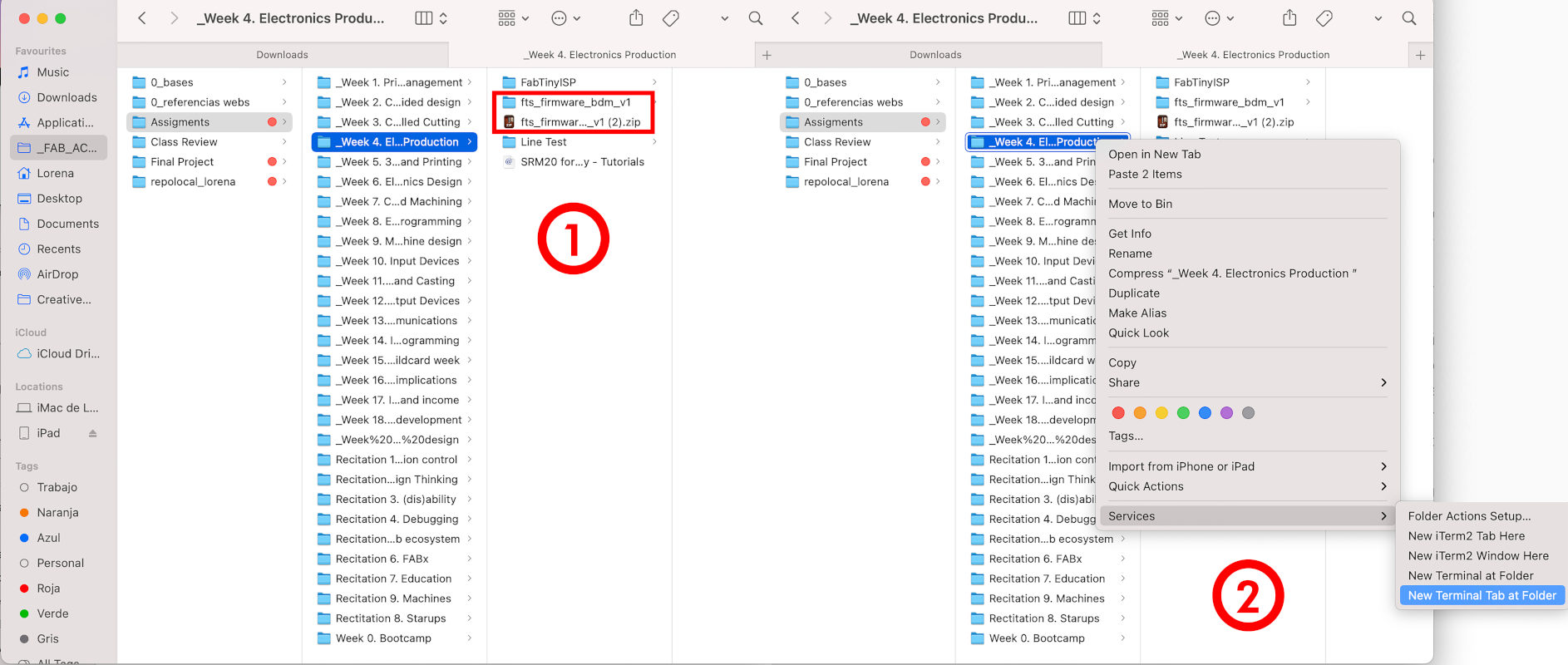
When we have it located, we unzip the folder, and we open Terminal inside the unzipped folder.
At terminal we have to follow the AVR steps by installing Homebrew. Once we have Homebrew installed, we have to follow this steps:
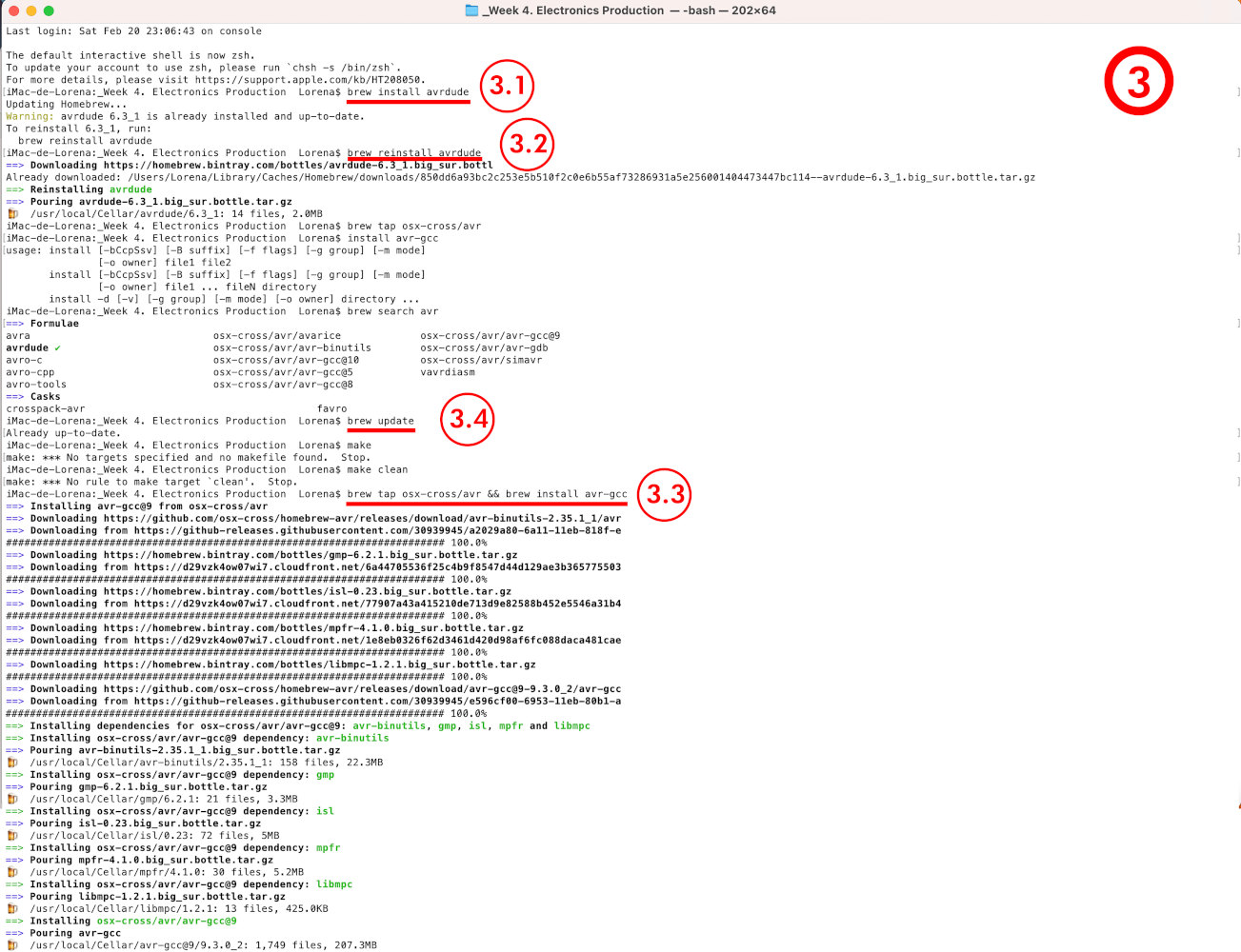
When we are done with Homebrew, we continue in terminal, and initialize the fuses programming by typing:
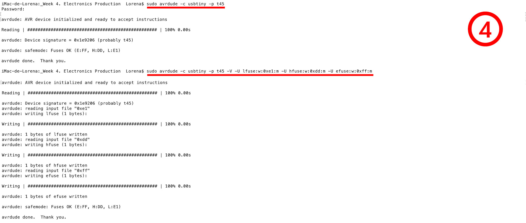
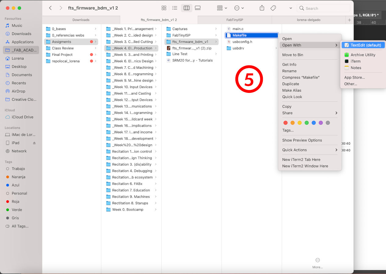
If at the moment, everything is Ok!, we leave the Terminal for a moment (without closing it) and open the Makefile file with TextEdit inside the firmware folder.
Here we have to check two things: the characteristics of the MCU, the programmer and the clock speed are correct:
And the next steps we need to take to program my FabATtiny 45.
When everything is confirmed and checked, we begin to generate the .hex and .elf file that we will need to start programming. So the first thing, at Terminal again, we open the firmware folder and follow these steps:
Then the files will be generated.
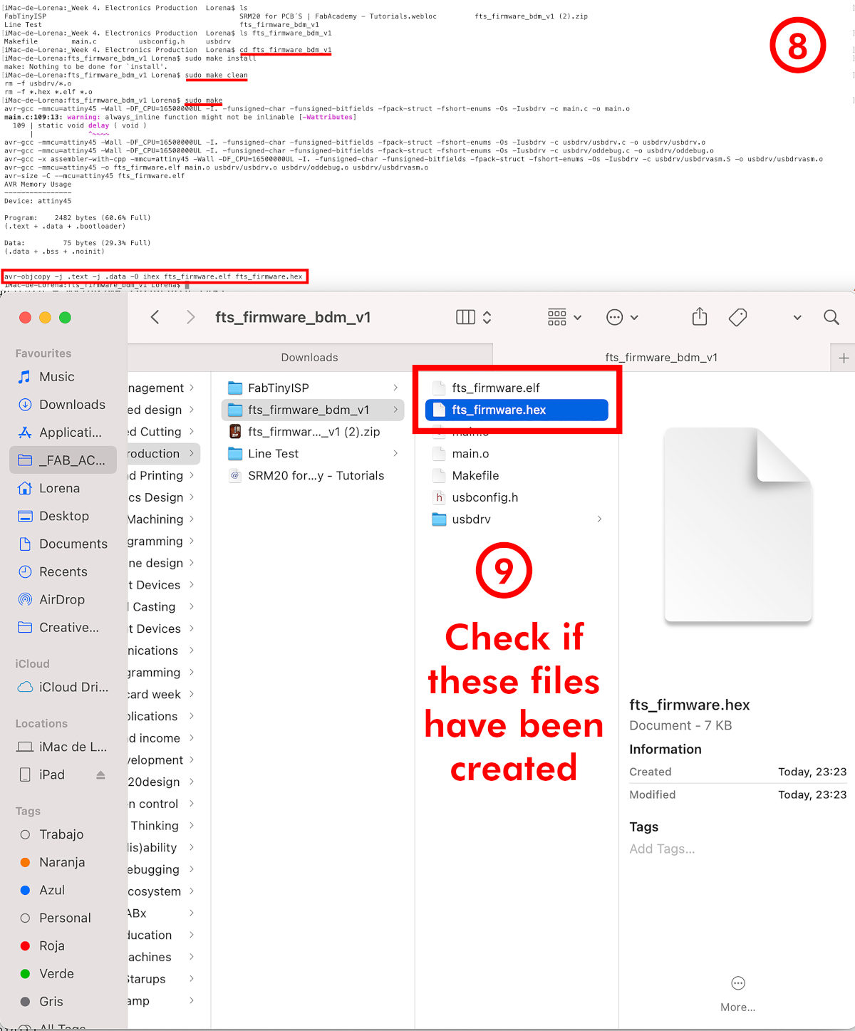
Now, the moment of truth has come!, we have to transfer all the data and programming the fuses bits inside our FabATtiny. So, we follow:

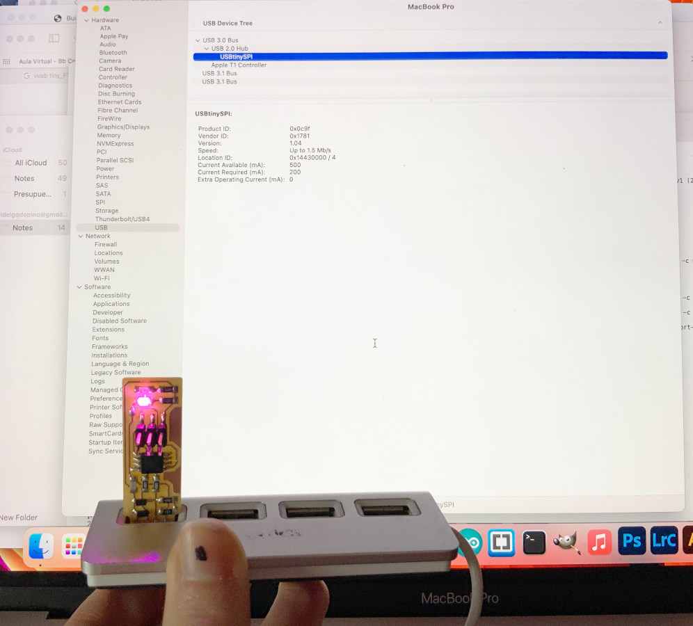
If so far everything has worked out Ok! again, we unplugged the other programmerm and just plugged in our already programmed FabATtiny. To check if the programming has been correct we go back to:
Apple Icon (click) > About this Mac > (Overview) System report ...> USB >...
And we check USB 2.0 hub > USBtinySPI appears with the same characteristics as the mother programmer. My pink FabATtiny is ready! 🎉🎉🎉
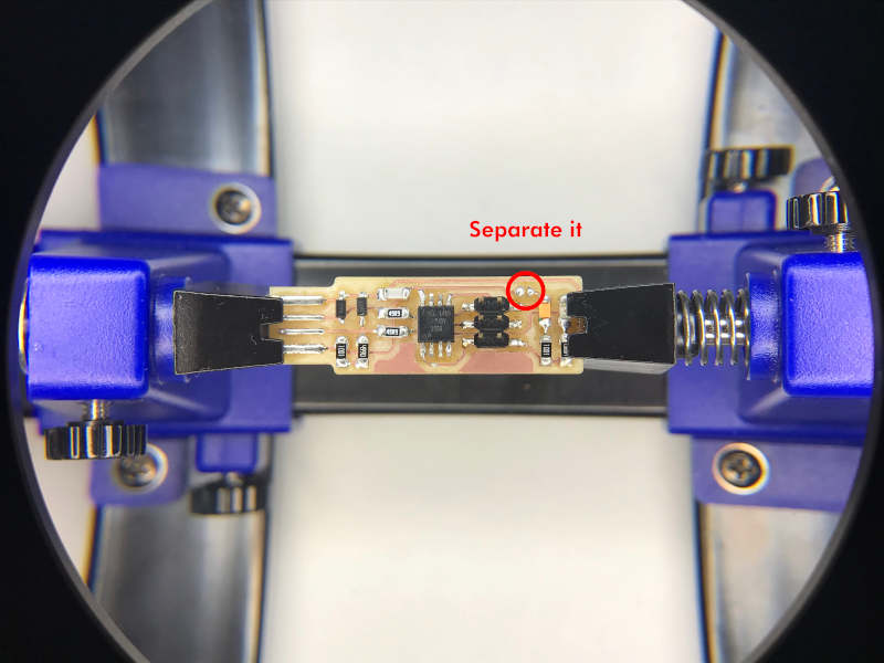
To finish, I have to do the last detail. To open the circuit I remove the tin ball that I had put on the board with the soldering iron, and finally we would have our first board programmed!.
"Mistakes you can make or may arise in your Mac OS" 😅
Before getting to this correct programming process, it took me approximately 5 hours of trial and error before I was able to program my FabATtiny. Here my crewmate Sergio and my instructor Nuria were witnesses.
From the beginning, I started to follow the Nuria´s Tutorial instructions and the make steps in Brian´s FabATtiny 45 tutorial, but this type of error appeared all the time: Bad CPU type in executable.
In these first steps I had to check well all the developers were downloaded and installed. (Xcode, Command Line Tools and the latest version of CrossPack).
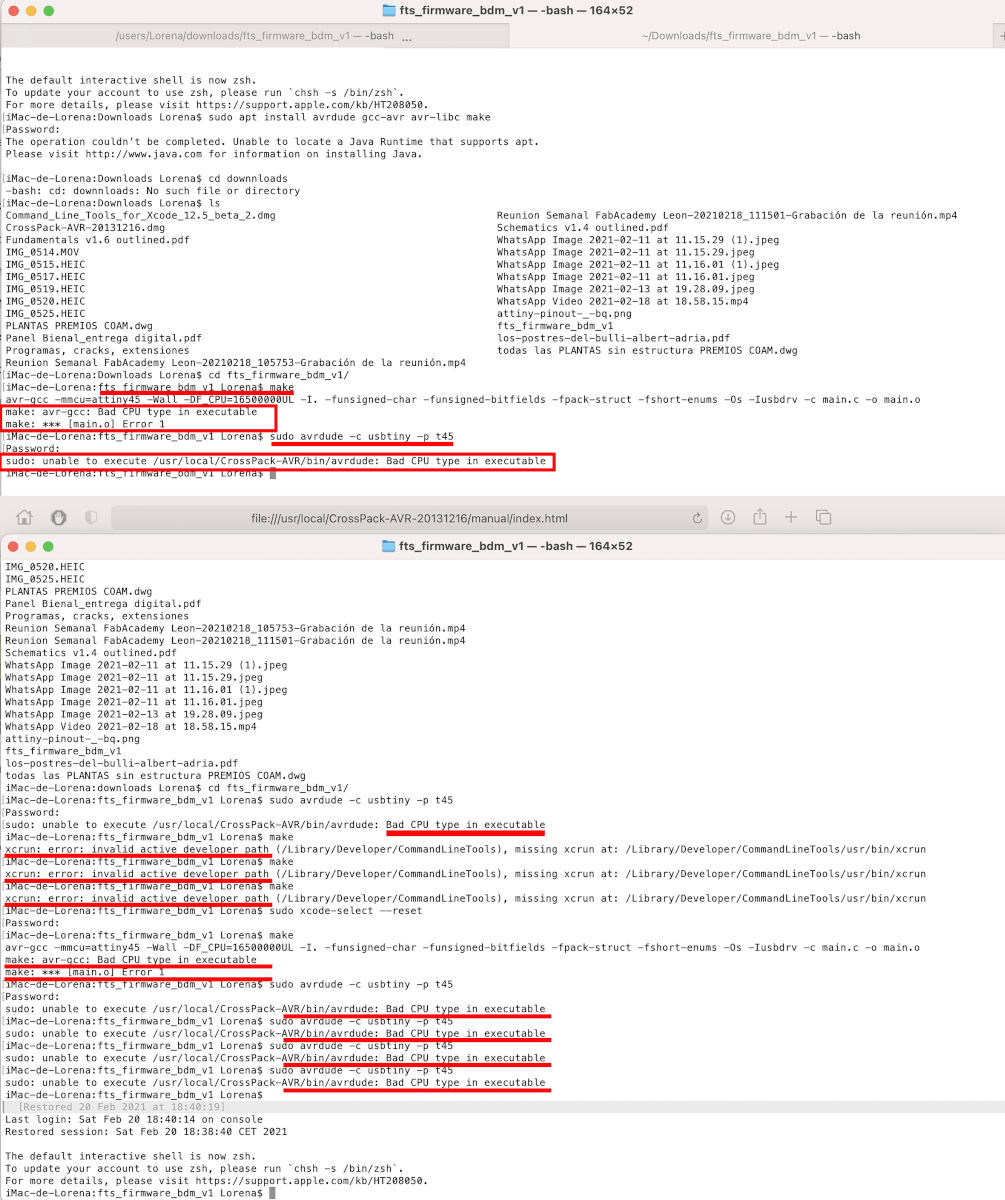
When I met with Nuria online, we checked Fab Academy students to see if other alumni like me had the same problem with their Mac OS laptops.
Here, we found two students, Harm Vanvugt and "Woma", who had had a similar problem and had to follow the AVR steps installing Homebrew.
On my first assigment, I already had trouble installing it because it considered Homebrew a shallow clone. And when I began to follow the AVR Steps, I had several errors again.
Finally, I fixed the homebrew error by typing at Terminal:
/ bin / bash -c "$ (curl -fsSL https://raw.githubusercontent.com/Homebrew/install/HEAD/install.sh)"
10 minutes ago, I finally fixed the error that I had in homebrew for weeks and managed to follow the AVR Steps.
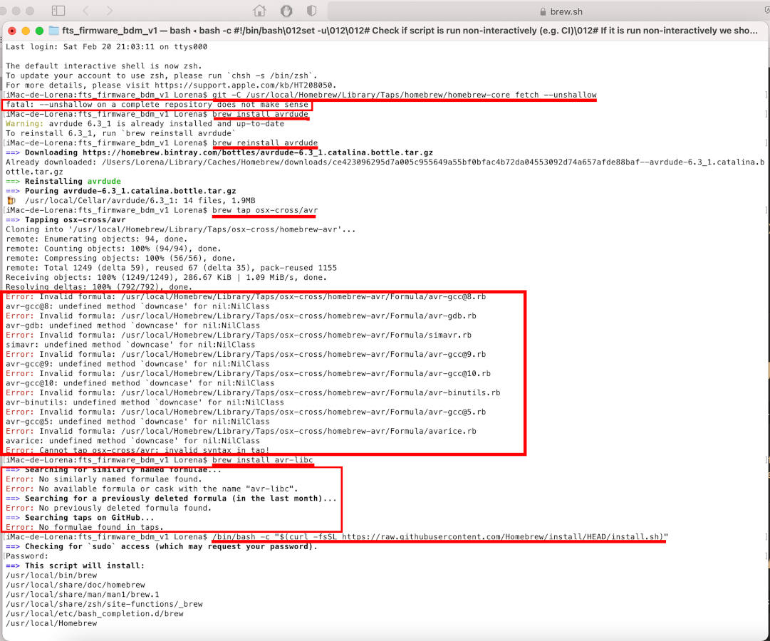
Another problem that I had while I was programming was I could not perform any type of action at the Terminal without using the "sudo" enablement as "superuser".
Due to the user security permissions that my Mac OS has, it does not allow me to perform many actions or movements to program. In the future, I will probably have to follow the same dynamics or use another computer to program.
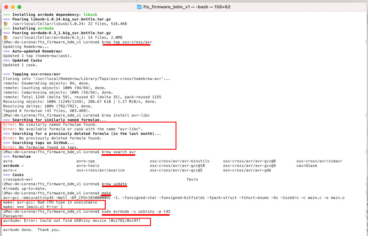
"More mistakes. Trying to program my first PCB board with my second PCB board" 😅😅
(21.02.2021 19:47 p.m). After getting my pink FabATtiny programmed, I wanted to see if I could do the same right programming process from my FabATtiny to my first (and slightly faulty) wooden board.
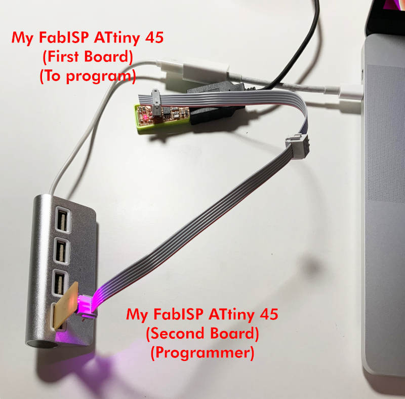
I followed the same steps from programming from sudo make clean to sudo make rstdisbl, and everything seemed correct!
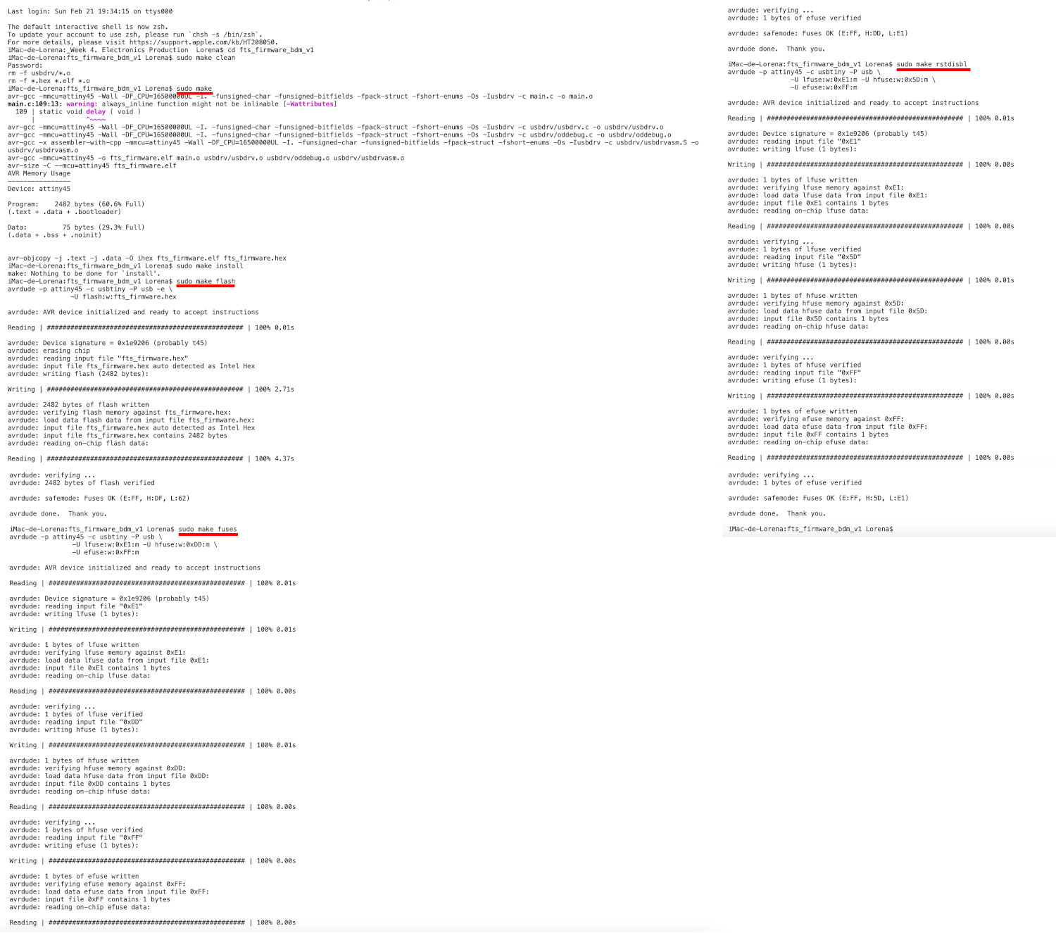
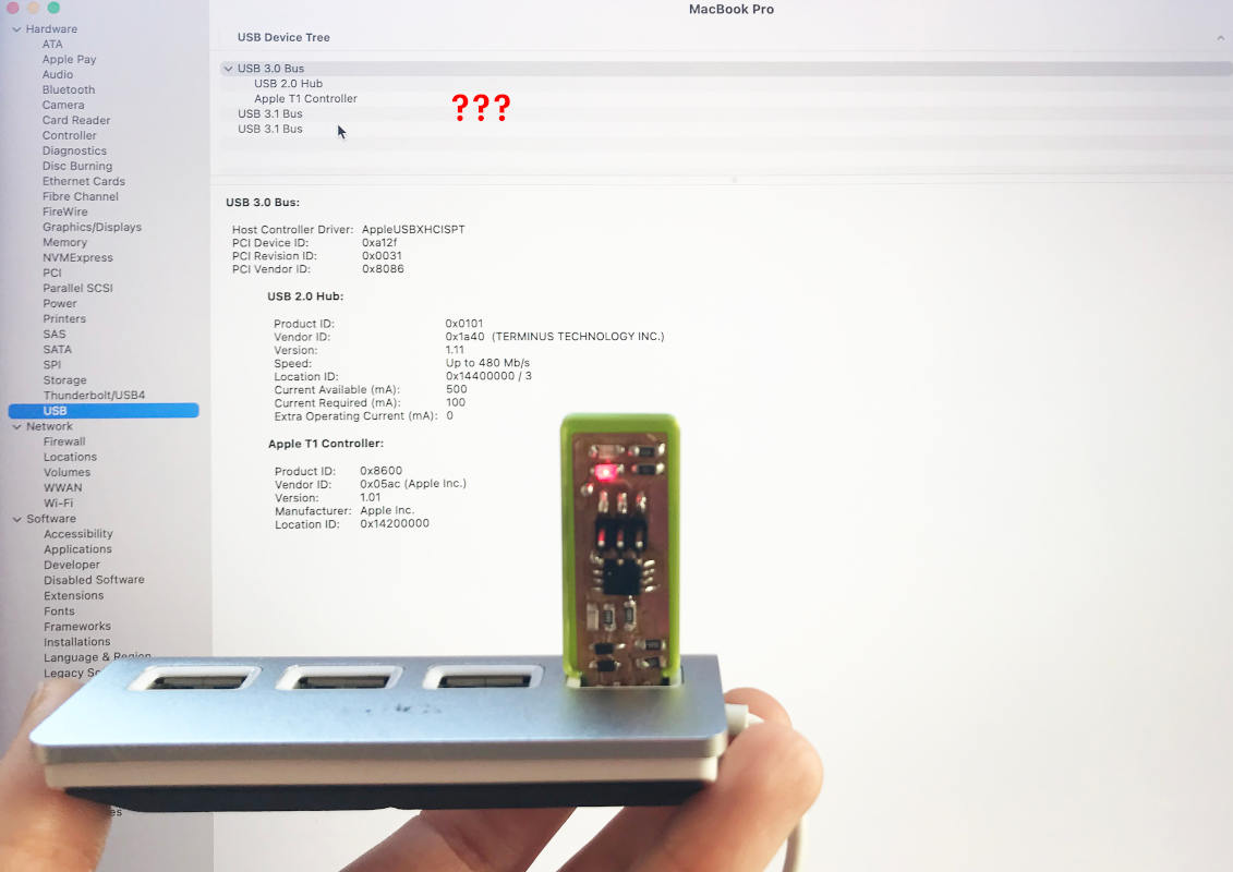
The issue came when I tried to check if my operating system recognized the new FabATtiny, and unfortunately it didn't recognize it! 😭😭
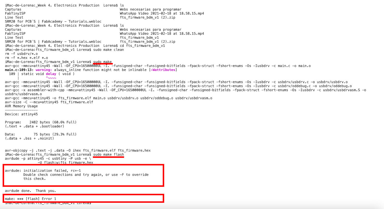
I tried to reprogram it, to see if I had made a wrong step, but I got to make flash, I had this problem: make: *** [flash] Error 1
When Monday arrived, I told my instructors about my issue in our Local Review, and they explained that the causes could be very diverse:
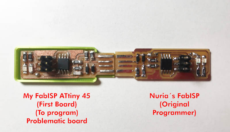
I've finally given up on this board 😪, but it has helped me learn what possible bugs I can find and what to do's and don'ts before "fixing" a program within our future boards.
