Final Project
Files
- water-saver project slide or poster
- water-saver project videoand this link on youtube.com
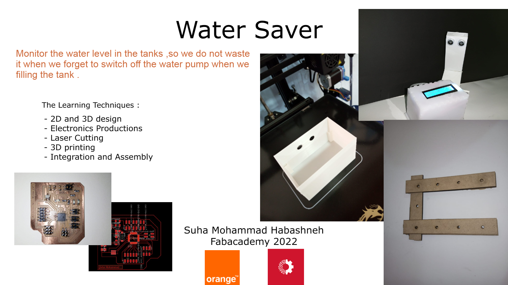
The Slide
Presentation video
Introduction
Jordan is the second most water scarce country in the world. Jordan’s annual renewable water resources are less than 100 m3 per person, significantly below the threshold of 500 m3 per person which defines severe water scarcity. Source
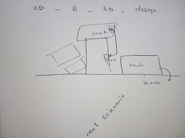
From here , the idea of the water-saver project came ,we are suffering in Jordan from water shortage , so we have to save every drop of it .
Because of we are using water pumps to fill the tanks , sometimes we forget to monitor the water level so we do not switch the water pump off then huge amount of water is wasted without using it in something useful . in addition to that when our tanks are above third and fourth floor (without elevator), it will exhaust people to monitor the water level going up and down stairs.
This project idea from my real life situation because I am the one of the family that is responsible to fill the tanks above the floor :) so I am happy that Fabacademy helped me to manufacture the device that would save at least a little and alleviate the labor and time consuming .
Water-Saver , What does it do?
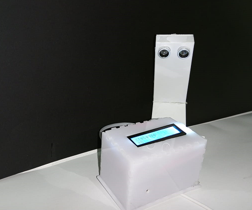
Water-Saver aims to save water from wasting during filling tanks and tell the user when they are empty , when they are full and could tell what is the percentage of water in the tank via Bluetooth module as communication and networking module and Mobile application as interface .
So , I can using the mobile application I made it using MIT App inventor with only clicking the button , I know the water level and this gives me an indication if I need to fill the tank and when .
Who has done what beforehand?
Zain company worked on the idea like this , but my idea differs that you can use Bluetooth module to receive the information about the water level without paying any fees or subscription.
and here is more details about “tanki” application that was launched by Zain company.
What did you design?
I designed a device that shows a message of water level as a text shown via mobile app on the user’s phone . So based on this status , the user will take the action of filling the tank when it needs to or stop the water pump when the tank is full .
But in general my project is divided into two stages in addition to the improvements in the future. :
First Stage
using Bluetooth HC-05 as a communication module , I will get information about the water level in the water tank , and this information will be delivered to my phone by using the application I will program . so once I click on the button “what is the water level do we have ?” the application will communicate with my device via Bluetooth and get the water level displayed in the screen . this stage will be presented as a final project for fab academy . but I will improve it as described below in the second stage section . in addition to another improvements that will be mentioned in “Project development assignment “
Second Stage
I will improve the first stage’s device so I will design a device that sends notifications for the user about the status of water in tank by SMS (Short messages service ) notifications to the user phone . So based on this status , the user will take the action of filling the tank when it needs to or stop the water pump when the tank is full .
What materials and components were used? Where did they come from? How much did they cost?
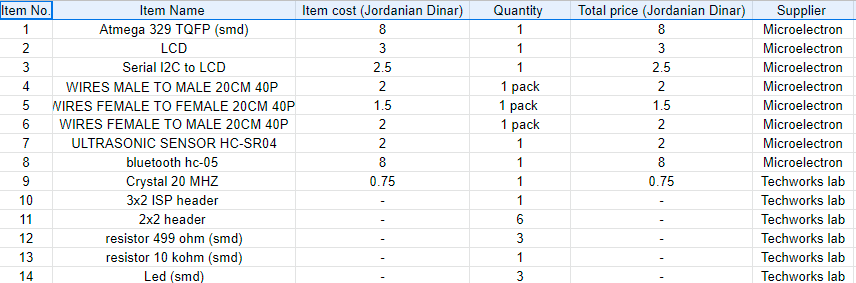
Here I answered the question via the following table , the cost is approximately 30 JD for components.
I used PLA material for 3D printing ,and MDF wood 5mm and Acrylic for laser cutting . the supplier is Microelectron company .
What parts and systems were made?
Input systems : ultrasonic sensor
Output system : LCD
Communication and networking : First Stage –> Bluetooth HC-05 and in the second stage –> sim800l GSM module
What processes were used?
-
2D and 3D design : for ultrasonic hand I made a 3D design , and for device cover and ultrasonic holder I made a 2D design .
-
laser cutting : using a laser cutter I made I device cover and holder for it.
-
3D printing : I made the ultrasonic hand using the PLA material with Creality 3D Ender 6 and 3 printer .
-
Electronic Production : using the MOD web site I generated my board .rml files then milled the board using Roland SRM desktop milling machine then I soldered the components on it .
-
Embedded Programming :I used Atmega 328 TQFP MCU and I connected the Input pins , output pins , power pins and ISP pins .
-
Interfacing and Applications : I made an application using MIT App inventor web site .
-
Networking and communication : I used Bluetooth HC-05
What questions were answered?
-
Is Ultrasonic sensor capable to measure the distances to the water . yes , it is .
-
Is Bluetooth capable to deliver the message within the range of use . yes it covers a 10 meter range .
How was it evaluated?
- Based on the successful communication between the user and the device via Bluetooth
- The ultrasonic must provide the right measured value for the water level .
What are the implications?
-
this project helped me a lot to be confident towards making any prototype for any idea starting from the idea to the final prototype . this make me able to help my students as I am holding the position of Fablab master at Orange Karak Fablab , so I feel that I can provide them with the good information about project processes , so I can advice them what works and what is not at satisfied level.
-
the project itself (if it is marketed well ) will affect positively on water shortage level and contribute in alleviation of water wasting , time and labor consuming in addition to reduce money spent on electricity and water wasted.
The following are the Process in details and how I benefited from the weekly assignment titles in my own project :
Processes
2D and 3D design
Files
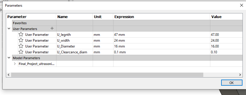
I used Fusion 360 software to design my device , as I learned from Assignment of computer aided design , I made a parametric design for ultrasonic hand as 3D design to be printed by Creality3D Ender 6 ,Creality3D Ender 3 printer . I made a 3D printed box to integrate the board and wires inside it , I printed it then I changed my mind and used laser cut box because it is more elegant . so I used the site that helps to make a box just you need to add some details of height ,width and length sides . the site is [here] (https://www.festi.info/boxes.py/) and here is my own design using fusion and it is parametric also .
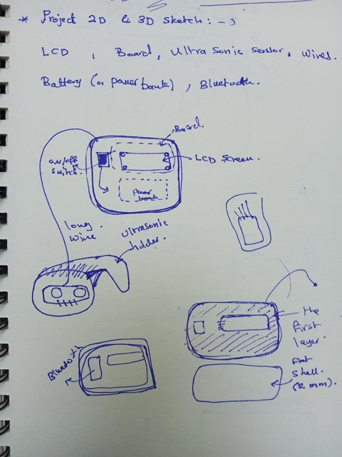
Here is the 2D sketch of ultrasonic hand :

it is a parametric design :
and here is the 3D design of ultrasonic hand :
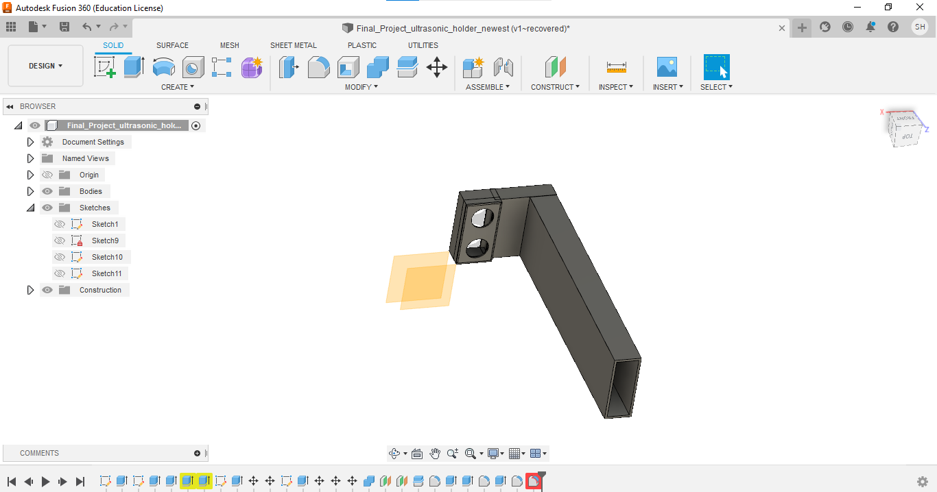
several commands , tools and concepts are used for the design , such as extrude ,dimensioning , creating sketches of lines and circles , offset , construction lines , sketched , bodies , change parameters ..etc.
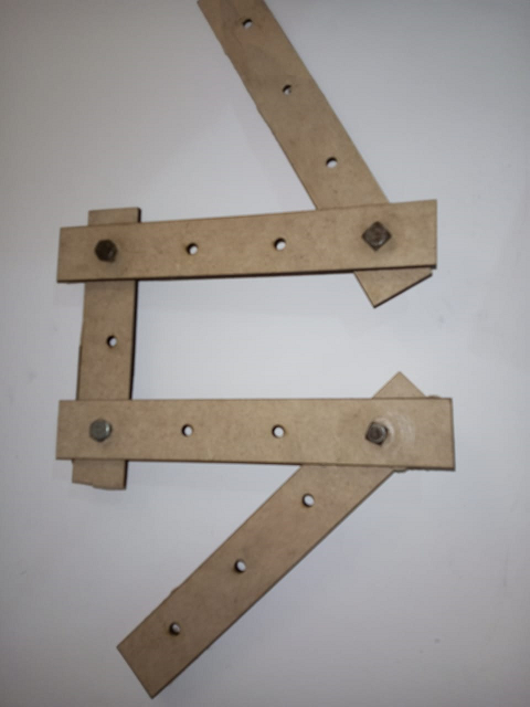
for wooden holder , here is a 2D sketch for it and it is parametric design
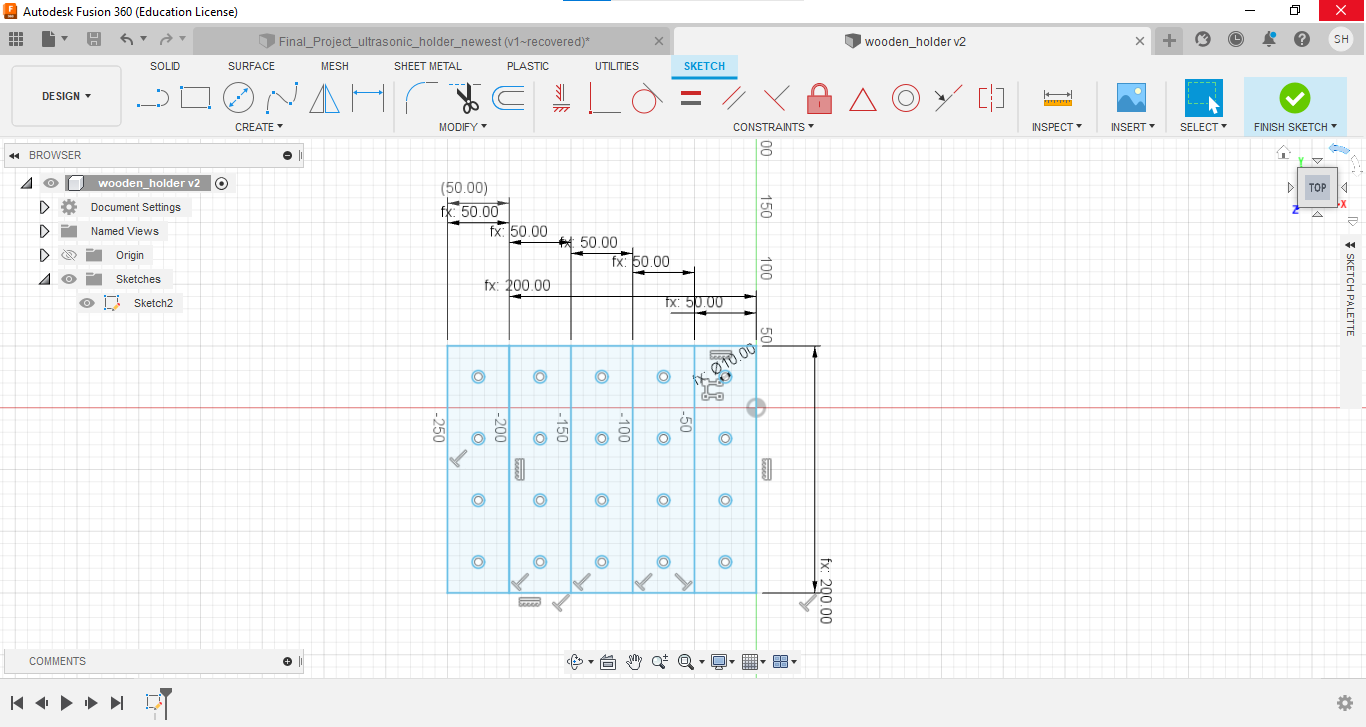
then used inkescape when I dealt with 2D design for wooden holder- which fixes the ultrasonic hand on the tank . I cut the wood to the pieces and then used bolts to assemble the wooden holder parts . mainly , the Rectangular pattern command heled me a lot.
Electronic Design
Files
final project eagle board file
final project eagle schematic file
After the research about the best Microprocessor that I can deal easily and close to the board that I am used to work with , and after asking my instructor Adriana Caberara , She suggested me to work with Atmega328 .
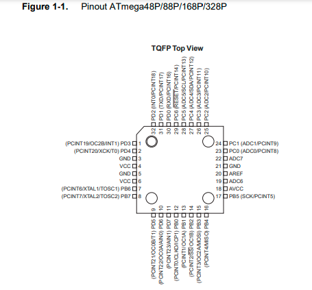
So from here I started to search about its pinout and tried to understand very well how each pin operate .
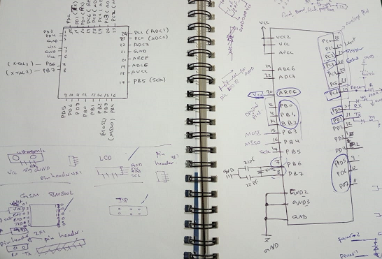
I used the data sheet of Atmega328 to know every thing I need about pinout of it .and here is the snapshot of pinout from the Atmega328 datasheet .
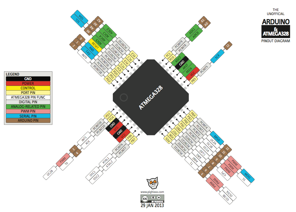
and the following figure shows the pins of ATmega328 and the corresponding pins on Arduino .
My Instructor Adriana told me about Satshakit which is “Satshakit is an Arduino compatible, fabbable board, and also an improved version of Fabkit.Source , So I was inspired by it and I tried to design my own board with the pins I need and some extra pin for using it in future .
so , to summarize which pins I used and for what , I inserted the following table :

and surly the board needs power so I added pins header for VCC and Ground .
Now , I will move to eagle software to start designing my own board , and here is the snapshot of schematic circuit :
and here is my eagle BOM
and here is the snapshot of board circuit
Electronics Production
Files
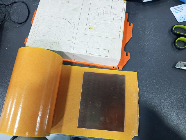
Now , Our circuit is ready to be milled using Roland SRM-20 machine , but I need to make a monochrome image for both traces image of the circuit and the outline .
So , first , I export the image of the board by going to the file menu in eagle software and choose “export” then browse where I want to save my image , the select “monochrome” and make the dpi equals to 1000 then hit OK .
The image is ready to be edited by “Gimp software” , so I made an outline image and traces image .
these two images will be uploaded to the MODS website to generate the .rml files .
the following is the image of outline :

and the following image is for traces of the circuit :
Now , I will go to the website of MODs
for Outline , I uploaded the png file of outline and I changed the dpi to 1000 , and I chose 1/32 bit , and I made the X,Y and Z origion to (0,0,0) :
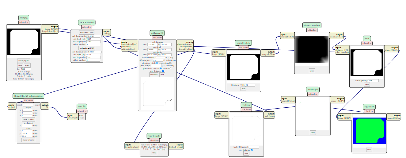
and here is the image resulted when I clicked on Calculate
to save the image as .rml file , I have to add “Save” module , by right click then choose “modules” then choose “save” from “file” then link this module input to the output of “Roland SRM milling machine” module.
for traces :
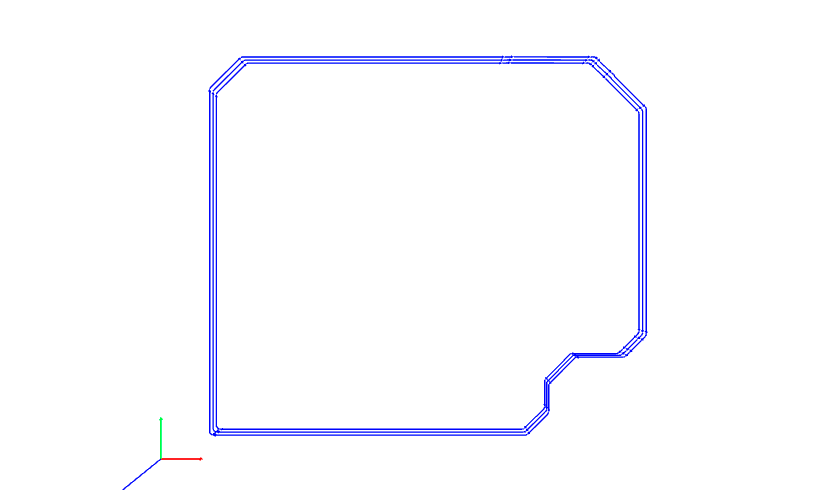
I uploaded the png file of traces and I changed the dpi to 1000 , and I chose 1/64 bit , and I made the X,Y and Z origion to (0,0,0) :
and here is the image resulted when I clicked on Calculate

to save the image as .rml file , I have to add “Save” module , by right click then choose “modules” then choose “save” from “file” then link this module input to the output of “Roland SRM milling machine” module.
prepare the board sheet that I will mill and fix it very well on the stand .
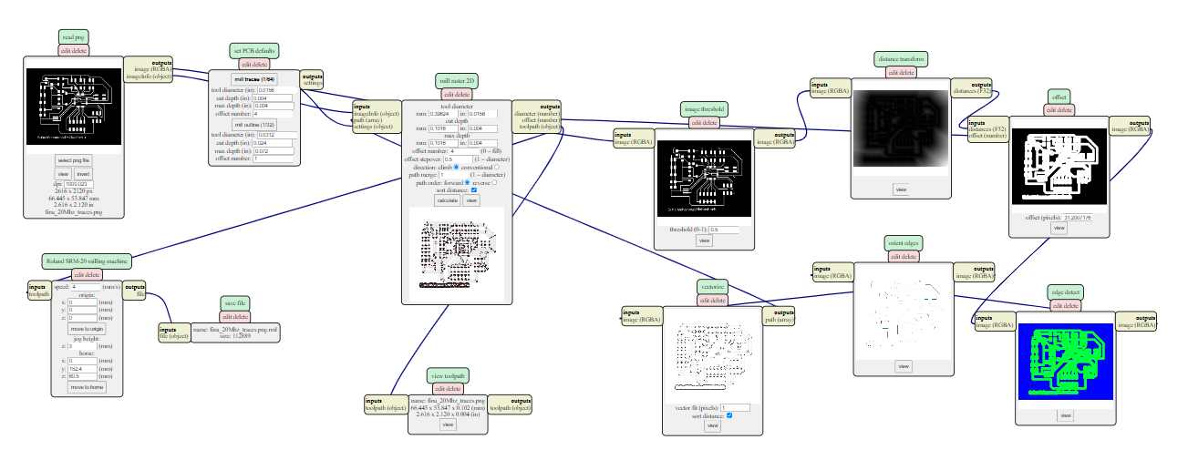
open the Vcarve software that is on the PC connected to the Roland SRM_20 milling machine . then choose the files to be milled , I will start with the traces before the cut (or outline) , so before doing any thing I need to choose the 1/64 bit and put it in its place in machine using screw driver. and start the calibration of X,Y and Z coordinates .
here I have to use the adhesion material then put the board on the wooden stand then insert the stand into the Roland SRM-20 Milling machine.
then I added he trace file and hit output .
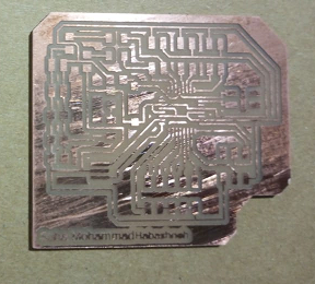
the machine will start milling .
The result of milling is like this :
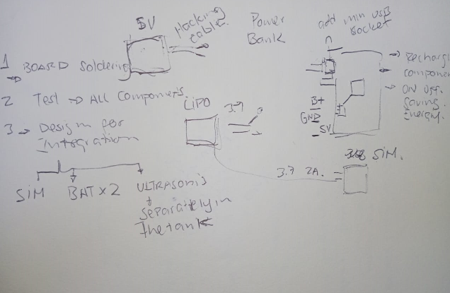
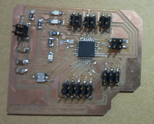
Soldering part :
using the soldering kit I soldered the component on the board and here is an image for the board after soldering .
Embedded Programming
Files
My board is ready to be programmed , So I will use Arduino as ISP programmer to accomplish my programming part .
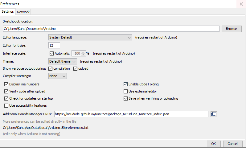
I need to install the library of ATmega238 to be able to communicate with the ATmega328 from Arduino . it can be downloaded from here
- Wiring :
using jumper wires , I connected the Bluetooth module , Ultrasonic sensor LCD to ATMega328 and connect ISP header of Arduino with the ISP header of Atmega328( Note : the reset pin of Arduino is connected to pc1 pin of atmega328 which is connected to reset pin (PC6)on it) , and the connections are based on this table .

I did the wiring and connections as in the table above ,I have to install the library of ATmega328 , copy this link : https://mcudude.github.io/MiniCore/package_MCUdude_MiniCore_index.json Go to the File–>Preferences–>Additional Boards manager URL –>then paste it there.
Now , Go to the file –>Examples–>Arduino as ISP
then go to Tools and select Board: Arduino uno and port is Arduino Com (COM number), you make sure that the Arduino board is correctly configured in the program .then compile and upload the program to our arduino board .
Now we just have to change the ArduinoISP programmer to Arduino as ISP , choose the “burn the bootloader”
Move on to the ATMega328 :
Go to the Tools–>Board–>MiniCore–>Atmega328
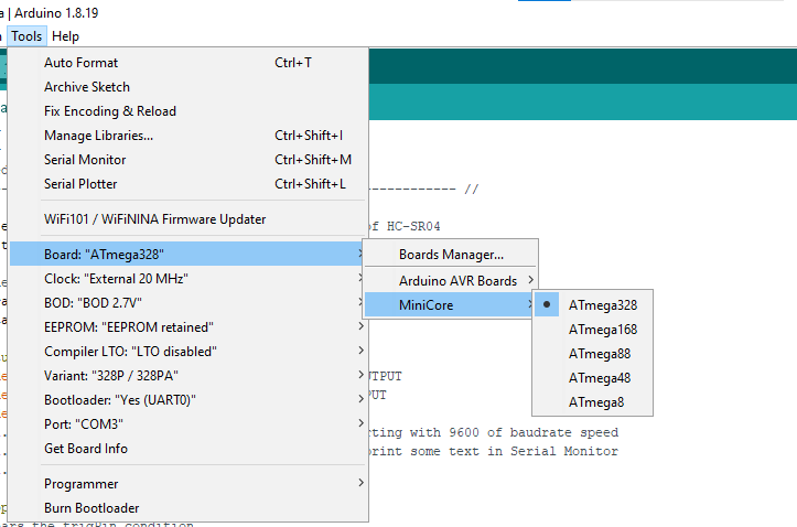
select the right port , and choose the 20 MHz for the clock .
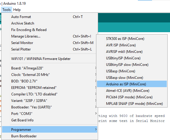
and make sure that the programmer is “Arduino as ISP”
important note : when we upload the code to the ATmega328 we have to press shift and upload button at the same time or go to the sketch menu–>upload using programmer.
Now we are ready to upload the codes for all modeul and devices connected to ATmega328.
Now I am ready to program the Input Device (Ultrasonic Sensor), Output Device (LCD) and the Networking and communication module (Bluetooth).
Input Devices (Ultrasonic):
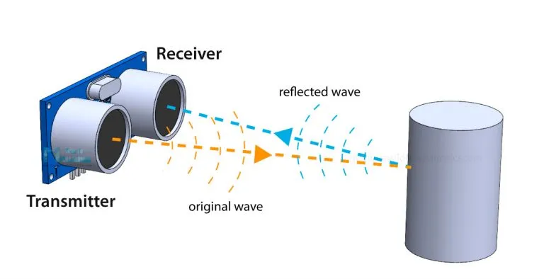
As I described the Ultrasonic concept in Input Devices week
It emits an ultrasound at 40 000 Hz which travels through the air and if there is an object or obstacle on its path It will bounce back to the module. Considering the travel time and the speed of the sound you can calculate the distance.Source
Now , Ultrasonic will emit ultrasound at 40 KHz to the water side , then it will measure the distance between the ultrasonic and the water level by using this code :
// Re-written by Arbi Abdul Jabbaar
// Tested on 17 September 2019


#define echoPin 5 // attach pin D2 Arduino to pin Echo of HC-SR04
#define trigPin 6 //attach pin D3 Arduino to pin Trig of HC-SR04

// defines variables
long duration; // variable for the duration of sound wave travel
int distance; // variable for the distance measurement

void setup() {
  pinMode(trigPin, OUTPUT); // Sets the trigPin as an OUTPUT
  pinMode(echoPin, INPUT); // Sets the echoPin as an INPUT
  pinMode(13,OUTPUT);
  Serial.begin(9600); // // Serial Communication is starting with 9600 of baudrate speed
  Serial.println("Ultrasonic Sensor HC-SR04 Test"); // print some text in Serial Monitor
  Serial.println("with Arduino UNO R3");
}
void loop() {
  // Clears the trigPin condition
  digitalWrite(trigPin, LOW);
  delayMicroseconds(2);
  // Sets the trigPin HIGH (ACTIVE) for 10 microseconds
  digitalWrite(trigPin, HIGH);
  delayMicroseconds(10);
  digitalWrite(trigPin, LOW);
  // Reads the echoPin, returns the sound wave travel time in microseconds
  duration = pulseIn(echoPin, HIGH);
  // Calculating the distance
  distance = duration * 0.034 / 2; // Speed of sound wave divided by 2 (go and back)
  // Displays the distance on the Serial Monitor
  Serial.print("Distance: ");
  Serial.print(distance);
Output Device (LCD)
Files
I used I2C shield to be connected to the LCD to minimize the number of wires used .
all I need is 4 wires : SDA ,SCL , Vcc and ground . I connected SDA of LCD with ADC4 of ATMega328 , and SCL of LCD with ADC5 , Vcc with Vcc and GND with GND.
I used LCD to show the distance between the ultrasonic and the water surface level .
Sure , I included the library of liquidI2C.h
and here is the code for using the LCD :
//YWROBOT
//Compatible with the Arduino IDE 1.0
//Library version:1.1
#include <Wire.h>
#include <LiquidCrystal_I2C.h>

LiquidCrystal_I2C lcd(0x27,20,4);  // set the LCD address to 0x27 for a 16 chars and 2 line display

void setup()
{
  lcd.init();                      // initialize the lcd
  lcd.init();
  // Print a message to the LCD.
  lcd.backlight();
  lcd.setCursor(3,0);
  lcd.print("Suha Mohammad");
  lcd.setCursor(2,1);
  lcd.print("FabAcademy2022");
   lcd.setCursor(0,2);
  }

  void loop(){}
  lcd.clear();
   lcd.setCursor(0,0);
   lcd.print("distance");
     lcd.setCursor(0,1);
      lcd.print(distance);
 delay(500);
}
Networking and Communication (Bluetooth)
to establish a communication between the device and my phone , I used Bluetooth module , so I connected Rx of Bluetooth with Tx of Atmega328 and Tx of Bluetooth with Rx of Atmega328 , Vcc with Vcc and GND with GND .
I used the SoftwareSerial.h Library
#include <SoftwareSerial.h>
SoftwareSerial mySerial (0,1); // RX, TX

void setup(){
mySerial.begin(9600);

}

void loop(){

if(mySerial.available()>0)
  {
     char data= mySerial.read(); // reading the data received from the bluetooth module
     switch(data)
     {
       case '1':
         mySerial.println(String(distance));
       }
     }
   }
Interface and application programming
Files
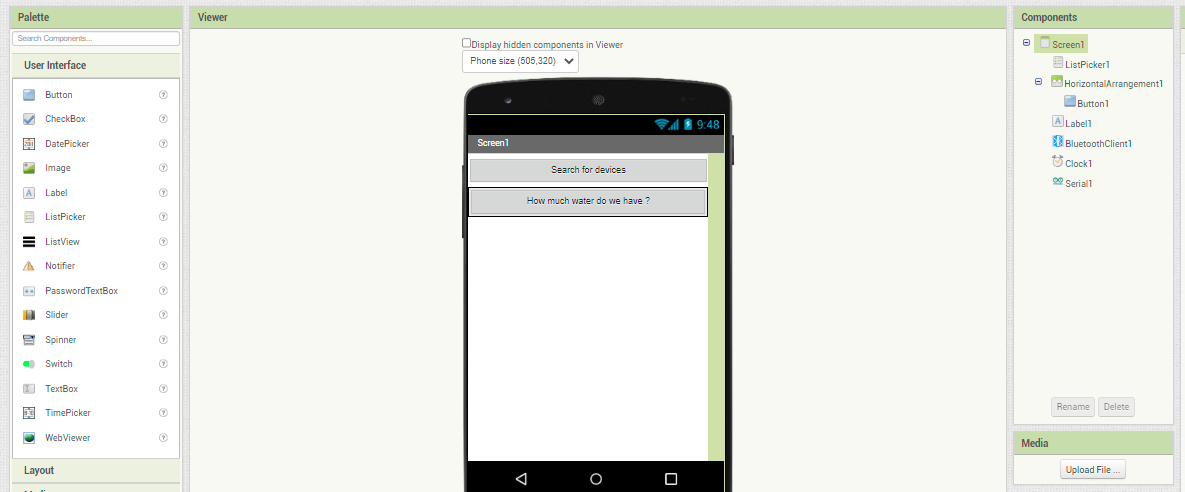
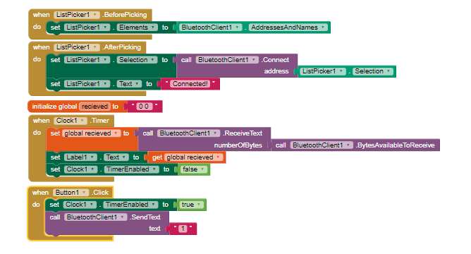
The best part is how to see the interaction between the phone and the device , So I used MIT app inventor and it was so helpful and reduced the time I will take if I used the ordinary software for applications programming .
so I inserted the code I did for interfacing between the device and my phone , so once I clicked on the button called “How much water do we have ?” it reads the Serial and give the distance readings from ultrasonic which is also displayed on LCD .
so here is a snapshot of the code :
Now I can download the application to my phone by going to Build –>Android .apk
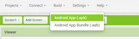
then send the .apk file to my phone and install it .
once you install the App , turn on the Bluetooth , then click on search for devices then select the Bluetooth name(or its MAC address) you use.
then click on the “How much water do we have ?” button
the text message will appear below the button .
The complete Code for the Water-Saver Project
# include <SoftwareSerial.h>
//YWROBOT
//Compatible with the Arduino IDE 1.0
//Library version:1.1
#include <Wire.h>
#include <LiquidCrystal_I2C.h>

SoftwareSerial mySerial (0,1); // RX, TX
LiquidCrystal_I2C lcd(0x27,20,4);  // set the LCD address to 0x27 for a 16 chars and 2 line display
// Suha edit : ultrasonic start
#define echoPin 5 // attach pin D2 Arduino to pin Echo of HC-SR04
#define trigPin 6 //attach pin D3 Arduino to pin Trig of HC-SR04


  //Suha edit :ultrasonic end
long duration; // variable for the duration of sound wave travel
int distance; // variable for the distance measurement

void setup() {
//Serial.begin(9600);
 mySerial.begin(9600);
 //pinMode(5, OUTPUT); // put your setup code here, to run once:

  lcd.init();
  // Print a message to the LCD.
  lcd.backlight();
  lcd.setCursor(3,0);
  lcd.print("water_saver");
  lcd.setCursor(2,1);
  lcd.print("Suha Mohammad");
   lcd.setCursor(0,2);
  //lcd.print("2022");
   //lcd.setCursor(2,3);
//  lcd.print("FabAcademy2022");
delay(1000);
//Suha ultrasonic start
   pinMode(trigPin, OUTPUT); // Sets the trigPin as an OUTPUT
  pinMode(echoPin, INPUT); // Sets the echoPin as an INPUT
//  Serial.begin(9600); // // Serial Communication is starting with 9600 of baudrate speed


  //Suha ultrasonic end
long duration; // variable for the duration of sound wave travel
int distance; // variable for the distance measurement

 }
void loop() {

 // Clears the trigPin condition
  digitalWrite(trigPin, LOW);
  delayMicroseconds(2);
  // Sets the trigPin HIGH (ACTIVE) for 10 microseconds
  digitalWrite(trigPin, HIGH);
  delayMicroseconds(10);
  digitalWrite(trigPin, LOW);
  // Reads the echoPin, returns the sound wave travel time in microseconds
  duration = pulseIn(echoPin, HIGH);
  // Calculating the distance
  distance = duration * 0.034 / 2; // Speed of sound wave divided by 2 (go and back)
  // Displays the distance on the Serial Monitor

   lcd.clear();
  lcd.setCursor(0,0);
  lcd.print("distance");
    lcd.setCursor(0,1);
     lcd.print(distance);
delay(500);

 if(mySerial.available()>0)
   {
      char data= mySerial.read(); // reading the data received from the Bluetooth module
      switch(data)
      {
        case '1':
          mySerial.println(String(distance));

      }
    }
  }
3D printing
Files
I printed the Ultrasonic hand and 3D box for device integration but I changed my mind for the box , I made it using laser cutter .
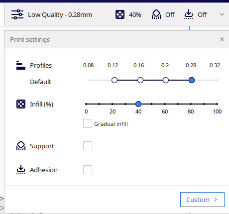
after I designed the Ultrasonic hand and the box with Fusion360 software I export the design file as .stl file to be imported by Ultimaker Cura software , in settings of 3d model in cura software , you can define the resolution of the print , the less number for profile the less accuracy and resolution and take less time to print and vice versa.
and for the infill , the more infill the more solid print but take longer time to print.
here is a speeded vedio for 3D printing Process :
Laser Cutter
Files
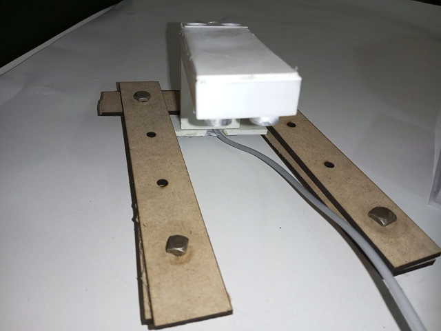
wooden_holder.f3d Note : I redesigned it. wooden peices dxf wooden peices circles I used Laser cutter to make the box for integrated the wires and module inside of it . and I used laser cutter to make the ultrasonic hand holder which will fix the ultrasonic above the tank . I used Beam flux leaser cutter to do this process .
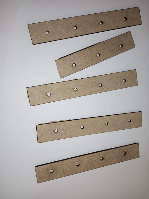
I used bolts to make some thing like clip .
this shot explain how it fix the ultrasonic holder
Future plan
-
I am planning to improve my project so I will replace the Bluetooth with Sim800L module that make me able to send SMS notification to the user phone with water level.
-
also I may make it more comprehensive so the device can measure any lquid level not only water .
-
I aim to make the device as IoT applicable
-
marketing the project idea so people can invest in it in the future .
The Licenses
I will choose the Attribution-NonCommercial-ShareAlike 3.0 Unported (CC BY-NC-SA 3.0). under this license ,you can Share — copy and redistribute the material in any medium or format and you can Adapt — remix, transform, and build upon the material, The licensor cannot revoke these freedoms as long as you follow the license terms.
The Acknowledgment
First of All , I want to thank Allah who helps me and made my dream come true to join fabacademy , I am so happy that I joined this journey .
then I thank my Family who support me always and encourage me to do my best .
I want to thank Orange telecommunication company for giving me this great opportunity .
I want to thank Techworks for facilitating this mission .
I want to thank Adriana , Murad , my collogues who helped me alot throught this journey .
and I want to thank Professor Neil , I respect him so much , thank you for your great efforts .
Thank you FabAcademy team , I hope to be instructor someday so be part of your team around the world.
and I want to thank creativity club - Karak because I started to think about fablab idea when I was holding the position of head of Technology and science department.
I want to thank my self :) because I didn’t give up !
Hero Shot