8. Computer controlled machining
Do something Big
Group Assignment
Safety
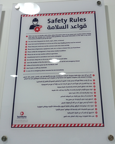
Before using any machine in the lab , we should follow the safety instructions to keep ourselves and our lab safe . the following signs explain the most important instructions to follow while we use the machine :
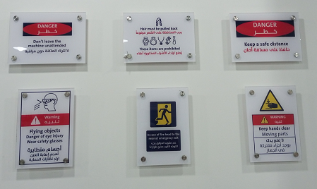
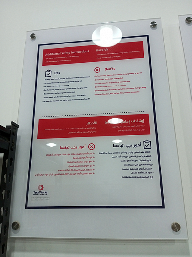
- Do not leave the machine unattended
- We have to wear sunglasses to avoid flying objects
- we have to keep our hands away from moving parts
- we have to keep a safe distance
- Do not wear accessories while you near the machine or while you are operating it.
- We have to wear a headset to avoid loud sound from the machine
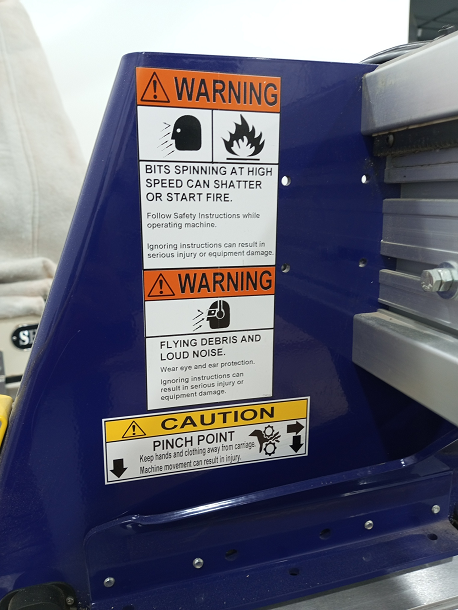
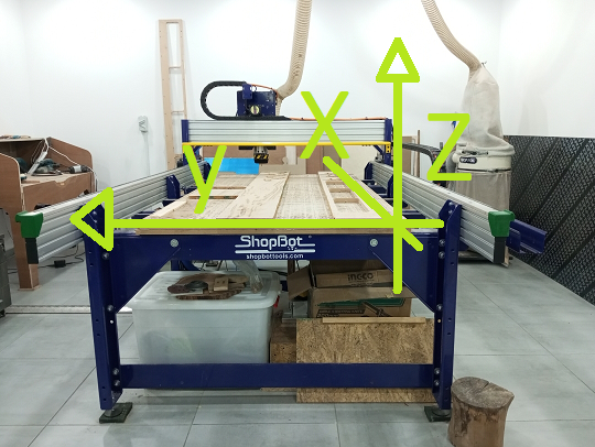
we worked on Shopbot (computer numerically controlled) which is a machine that uses a cutting bit that rotates at a very high speed to remove material from a part. Source
ShopBot Specification
PRSstandard96 The size of the bed of that ShopBot is 4 x 8 feet (or 48 x 96 inches)(2440x1220mm).
1220mm of travel on the X axis
2440mm travel feet on the y-axis
152mm Z-axis travel (with one-inch cutter placed)
Collet size ER25 for cutters
The long side is x and the short side is y ,the height is z
Tools :
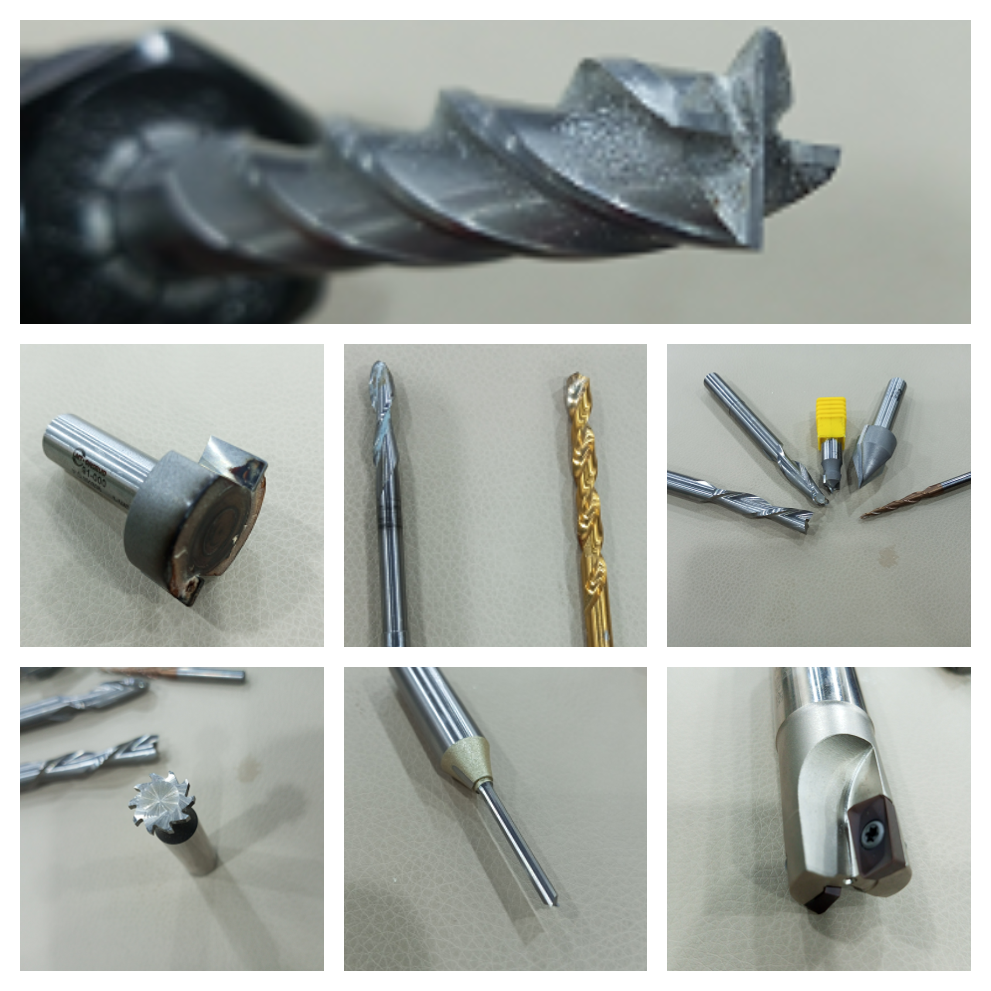
There are many types of tools used with Shopbot machine :
-
Straight tool 4 mm .
-
Down cut tool :mainly used for wood .
-
Up cut tool : mainly used for metals
-
Solid Carbide tool :which all of its parts are from carbide .
-
Compression tool : used both down cut and up cut .
-
Ball nose end mill
-
Radius tool
-
Taber end mill
-
Indexed end mill
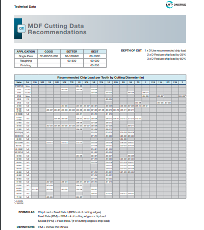
This site is very useful for cutting tools data sheet . for example : if you want to know the chip load(This is simply the thickness of a chip which is formed during the machining of material) and feed rate and speerd(RPM) for the specified cutting tool for MDF wood material you can return to this data sheet.
Wood types
There are different types of wood materials can be used with this machine :
-
Plywood
-
MDF(medium-density fiberboard)
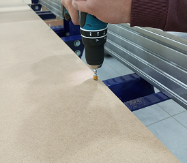
The Work piece Fixing
To fix the work piece we use the drill and screws to make the wood piece stable .
Individual Assignment
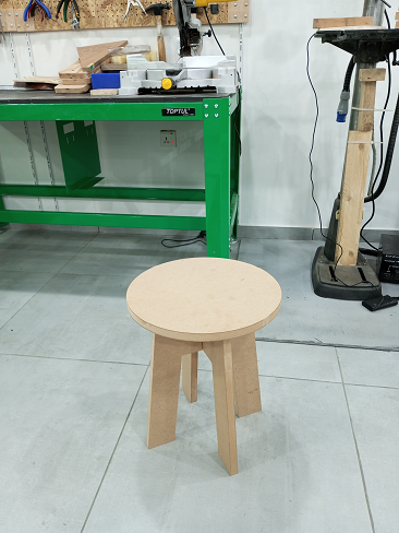
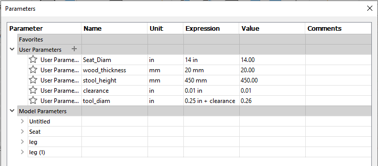
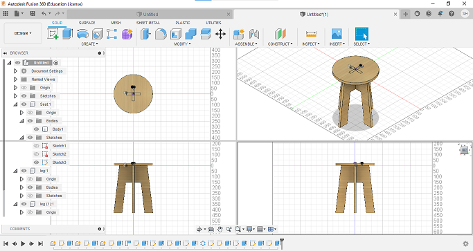
I designed a stool using fusion 360 software , I made it parametric design so I can change the length , radius , thickness and clearance according to my needs .
I followed the steps of this tutorial from Autodesk Fusion 360 to design my stool .
the design consists of three parts :
- the stool top
- the first leg
- the second leg
for I used the mdf wood material , I measured its thickness and it was 22.09 mm so the thickness parameter is equal to 22.09 mm , adding the clearance to it makes an open room for wood to inserted easier .
Generally , the design has started with 2 d design for each part then extruded it to the thickness value to have the 3d design .
after finishing the 3d design , I clicked on top sketch then saved it as dxf file and this repeated for each first leg and the second leg .
Now we are ready to work wth our CAM software called VCarvePro .
- open the VCarvePro program
- select file -> New
- in job panel , you can see different settings , leave them as default unless you need to change them , I changed the nits to mm instead of inches. choose ok .
- file -> import ->Import vectors
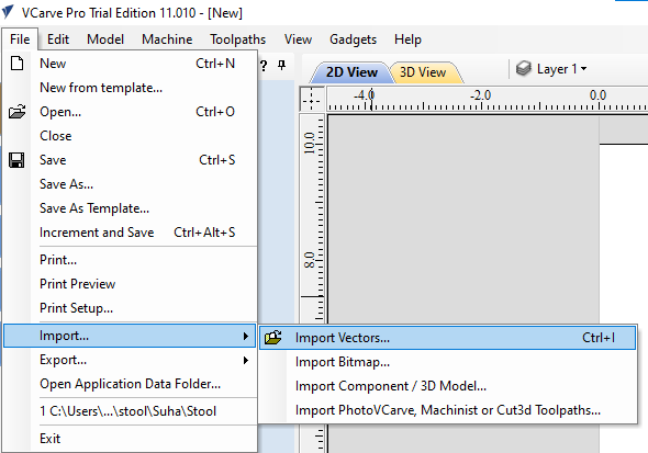
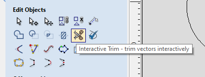
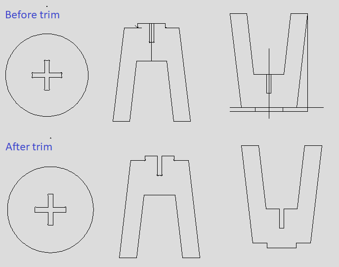
- now select your dxf files and import them to the white space, by using move
selected objects and bring them to the wanted place. - use interactive trim tool to trim unwanted lines .
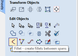
- Now I want to modify the t-bone using fillet tool (note : remove the rounded t bone first by trim then use extend tool to make a corner)
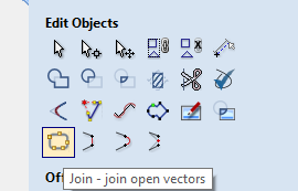
- select join tool to join all the lines before applying fillet .
- choose the tool radius and the T-bone fillet as below :
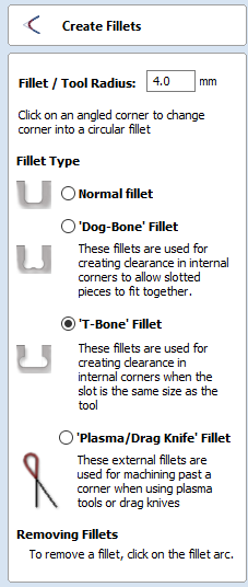
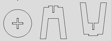
- the result after fillet :
-
Now we will do “Nesting” via nesting tool , the purpose of this tool is to
alleviate the wasted space and materials after cut . we determine the tool diameter by 6 mm.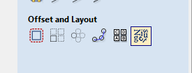
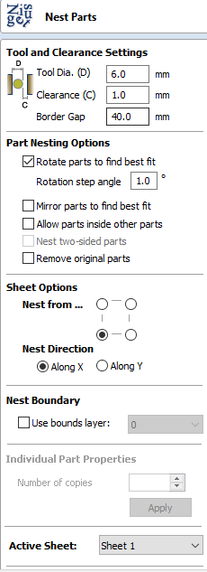
The result of nesting process is like following :
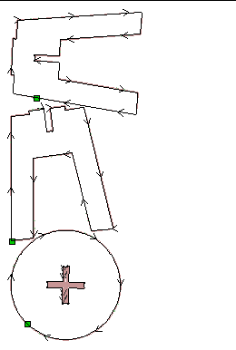
- Now we move to the toolpaste menu and apply the profile toolpath operation with the following inputs :
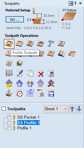
and the settings are :
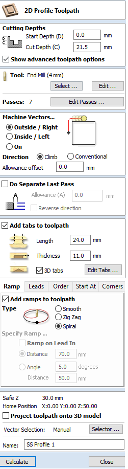
-
press calculate.
-
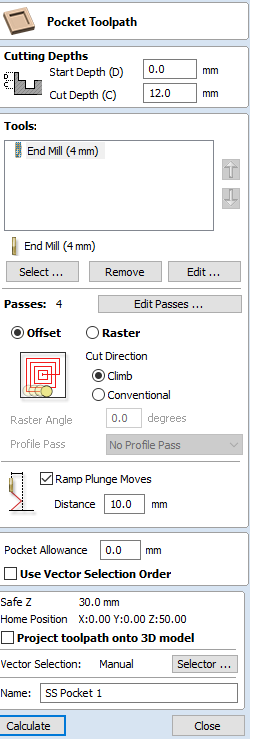
and from the the toolpaste menu we apply the pocket toolpath operation with the following inputs :
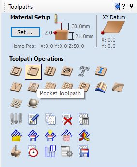
and the settings are :
-
press calculate.
-
Now we save our pocket and profile files in separate files with sbp
extensions. by checking the toolpath file then choose -save the toolpath-. -
make sure that the wood board is screwed .
-
turn the shopbot on and wait untill it is warmed .
-
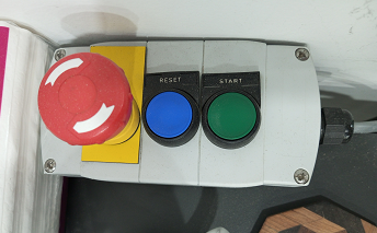
open the shopbot command console
- if the stop button is ON message appears then press on reset button.
-
Now we have to calibrate X,Y and Z.
-
Go to Key Pad and enter the x , y enter the wanted values for their positions then press on Zero.
-
for Z position , make a distance of 10-15 mm from the surface of plate
to the tip of endmill . . -
Now connect the alligator clip to the body of the machine .
-
click on position .
-
click ok for the message appeared then click ok .
-
click on cut parts
-
the machine will ask us to start cutting .click ok
-
turn on the dust extractor.
Hero Shot