9. Embedded programming
Group Assignment
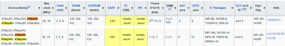
we used the programmer MCU “Attiny44” and board MCU “Attiny45”
the main difference between them is that the pin numbers of each .
8 pins for Attiny45 and 16 pins for Attiny44
the pinout of attiny44 MCU is inserted below in in individual assignment .
and the pinout of attiny45 MCU is here :
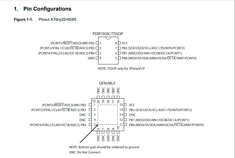
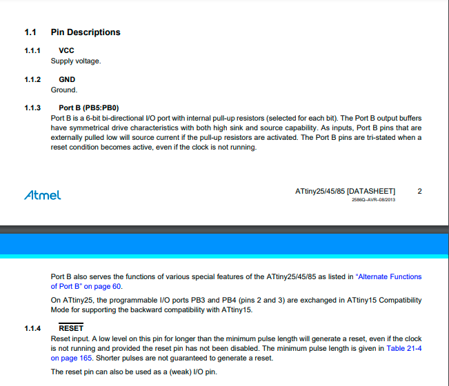
the attiny45 datasheet
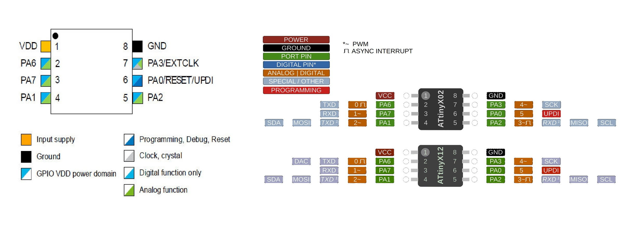
in addition here is a SAM D11C Microprocessor , its pinout and more information about it :
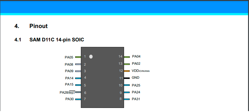
The Atmel SAM D11 implements the ARM® Cortex™-M0+ processor, which is based on the ARMv6 Architecture and Thumb®-2 ISA. The Cortex M0+ is 100% instruction set compatible with its predecessor, the Cortex-M0 processor ,and upward compatible to Cortex-M3 and M4 processors.
The ARM Cortex-M0+ core has two bus interfaces: - Single 32-bit AMBA®-3 AHB-Lite™ system interface that provides connections to peripherals and all system memory, including flash and RAM - Single 32-bit I/O port bus interfacing to the PORT with one-cycle loads and stores.
The following table gives us information about SAMD 11C it has 14 pins (while the attiny45 has 8 pins ) and 12 GPIO , 16 KB flash and 4 KB SDRAM .
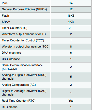
and here is the data sheet of samd11c
if I want to program this MCU using Arduino then I have to know the interfacing between pinout of samd11c and Arduino pins ,thanks for [Adrian Torres] who mention that in his site .
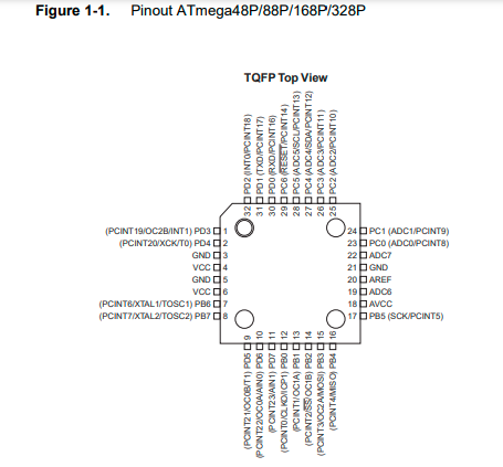
Since I worked on Atmega238 in my final project , so it is good to tell about it in this assignment :
Atmega328 it is 8-bit AVR Microcontroller with 32K Bytes In-System Programmable Flash has 32 pins , the followings are some of its feature
● 1Kbytes EEPROM
● 2Kbytes internal SRAM
● Write/erase cycles: 10,000 flash/100,000 EEPROM
● Optional boot code section with independent lock bits
● In-system programming by on-chip boot program
● True read-while-write operation
● Programming lock for software security
it operates on 2.7 volt to 5.5 volt. and it is low power consumption as it mentioned in the datasheet
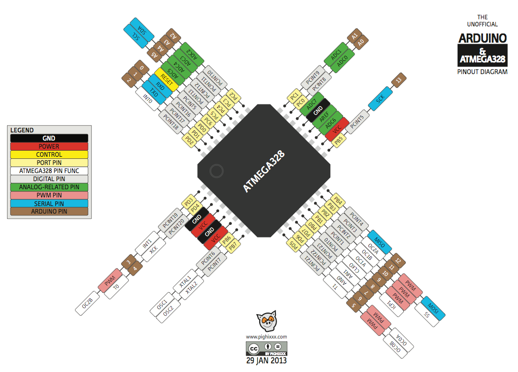
from my experience with both attiny44 and ATmega328p , I found it easier for me to deal with the ATmega328 since it is the same microcontroller used in Arduino in addition to that I tried to connect LCD with Attiny44 and I faced problem with that , so I found the ATmega328 is more powerful and supportive than Atting44 .
here is a snapshot of how to interface ATmega328 with Arduino :
Individual Assignment
I will use the board I designed in week 7 “Electronic Design “
I program the board by a programmer ISP tiny
Step 1 : Download and install the Arduino IDE from here.
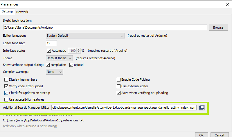
Step 2: Install the Library of Attiny from here , extract it in Arduino Libraries folder. after that go to file -> preference ->copy this link https://raw.githubusercontent.com/damellis/attiny/ide-1.6.x-boards-manager/package_damellis_attiny_index.jsonand paste it in Additional boards manager URLs .
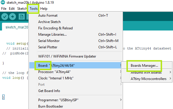
Step 3 : Go to Tools -> board manager
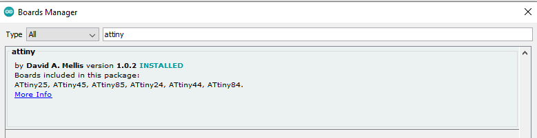
write attiny in search bar then once it is appeared click on install .
Step 4 :Back to the Assignment week 5 and install the GNU make , Tool Chain , avrdude as in the steps there.
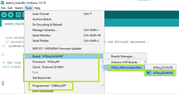
Programming the board :
- Make sure that you have the same as the following picture:
Now we are ready to upload the following code to the board :
void setup() {
  // put your setup code here, to run once:
pinMode(2,OUTPUT);// here we define the pin 2 as output which corresponds to PB2 on attiny44
pinMode(3,OUTPUT);//here we define the pin 3 as output which corresponds to PB3 on attiny44

}

void loop() {
digitalWrite(2,HIGH);//sending the digital value 1 to the board to the pin 2
delay(100);// make some time interval between the digital high and low. which is 0.1 second
digitalWrite(2,LOW);//sending the digital value 1 to the board to the pin 3
delay(100);
digitalWrite(3,HIGH);
delay(100);
digitalWrite(3,LOW);
delay(100);

}
here is a video of the output result :
as you notice , I use the pin 2 and 3 on Arduino that correspond to PB2 and PB7 on Attiny44 respectively.
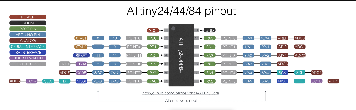
from attiny44 datasheet that help us to know the pinout of the attiny44 MCU , and here is the snap picture of pinout :
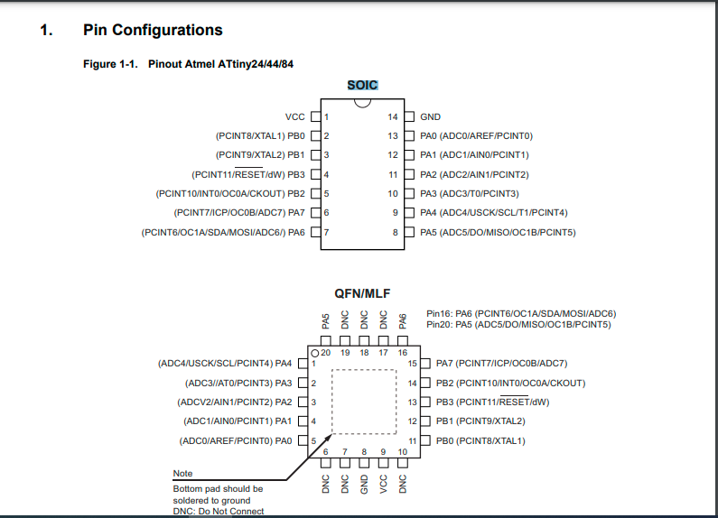
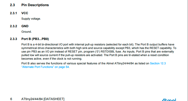
and here is the description of pinout from the same datasheet:

Problem and Fixes
during my work on this assignment I faced the problem :
“avrdude: initialization failed, rc=-1 Double check connections and try again, or use -F to override this check.”
I found that the problem was that I reverse the wires connections between the programmer and the board . in addition to that I had to omit the extension “make” from makefile.make .
Controlling the LED on Attiny44 board using push button :
the push button is attached at PB2 on Attiny44 which corrosponds to pin 8 .
here is the code :
int buttonState=0;

void setup() {
  // put your setup code here, to run once:
pinMode(2,OUTPUT);// here we define the pin 2 as output which corresponds to PB2 on attiny44
pinMode(3,OUTPUT);//here we define the pin 3 as output which corresponds to PB3 on attiny44
pinMode(8,INPUT);//here is the input pin for push button
}

void loop() {

buttonState=digitalRead(8);//Reads the value 1 or 0 on pin 8

if(buttonState == 0){


digitalWrite(2,HIGH);//sending the digital value 1 to the board to the pin 2

digitalWrite(3,HIGH);

delay(50);

digitalWrite(2,LOW);
delay(50);
digitalWrite(3,LOW);
delay(50);


}else
digitalWrite(2,LOW);
digitalWrite(3,LOW);

}
and here is the video: