14. Networking and communications
Group Assignment
There are different types of communications protocols such as UART,SPI and I2C which are the common hardware interfaces and used in Microcontroller Development .
Here is a detailed information about each one of them :
SPI Interface
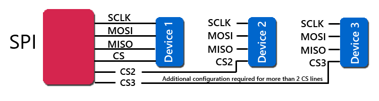
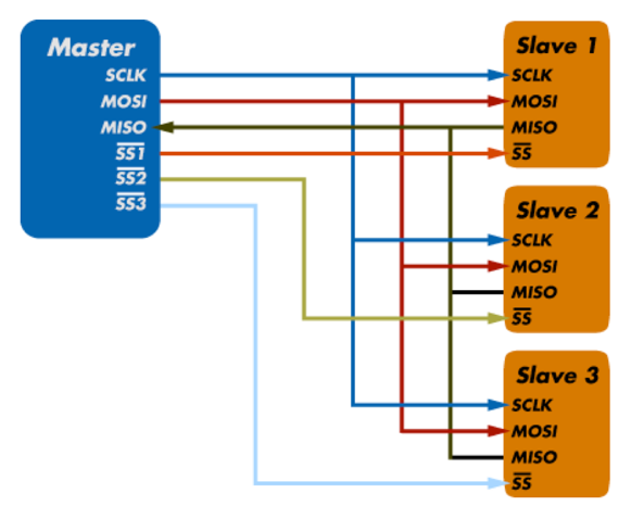
SPI (Serial Peripheral Interface) is a serial communication protocol often used in embedded systems for high-speed data exchanges between devices on the bus. It operates using a master-slave paradigm that includes at least four signals:
- a Clock (SCLK)
- a Master Output/Slave Input (MOSI)
- a Master Input/Slave Output (MISO)
- a Slave Select (SS) signal.
The SCLK, MOSI, and MISO signals are shared by all devices on the bus. The SCLK signal is generated by the master device for synchronization, while the MOSI and MISO lines used for data exchange. Additionally, each slave device added to the bus has its own SS line. The master pulls low on a slave’s SS line to select a device for communication.
SPI communication supports Full-Duplex Communication
that means both the master and slave can transmit data simultaneously.
SPI features
- SPI protocol is ideal for data-streaming applications.
- It also has no maximum speed; data speeds in excess of 100 MHz have been achieved.
I2C
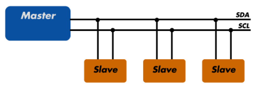
I2C (Inter-Integrated Circuit) is a simple communication protocol often used in embedded systems as a way to transfer data between a master (or multiple masters) and a single slave (or multiple slaves) device. It is a bidirectional two-wire serial bus that uses serial clock (SCL) and serial data (SDA) wires to send and manage data bit by bit between devices connected to the bus.
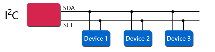
In I2C operations, the master controls the exchange of data between the devices. A master device will signal to a slave in order to send data or request a response. To accomplish this, all slave devices must have a unique address that is included in the I2C message.
When sending data over the bus, each I2C message includes an address frame of the slave device and one or more data frames containing the data being transmitted. The message also includes start and stop conditions, read/write bits from either the master or slave, and ACK/NACK bits sent from the receiver for error checking.
I2C is considered to be synchronous, meaning it operates using a serial clock. The clock is driven by the master device which allows the output of bits to be synchronized to the sampling of bits by the clock signal shared between the master and the slave.
The standard data transfer rate of the I2C protocol is 100 kbps, although data speeds of up to 5 Mbps are possible with I2C devices configured in “fast mode” or “ultra-fast mode”.
The receiving chip must be informed of the other chip’s transmission pace because no clock is transmitted. To correct for overshoot and ringing, a series resistor should be added to the UART line, just like with SPI. The signals are single-ended, which makes them more noise-sensitive, especially over long distances. Two additional signals, CTS (Clear to Send) and RTS (Request to Send), are sometimes added to the connection to improve its integrity. We perform a group assignment where we use potentiometers to adjust led intensity. The led is connected to a slave controller board (Aybak board), and the potentiometer is attached to a master controller board (Amin board). The potentiometer signal is wired to pin A0 on the master board, the led is wired to pin 5 on the slave board, and the final connections are TX on the master board to RX on the slave board and RX on the master board to TX on the slave board.
UART
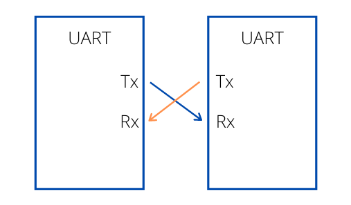
UART, or Universal Asynchronous Receiver/Transmitter, is a physical circuit in a microcontroller or single integrated circuit (IC) that is used to implement serial communication between devices in an embedded system. Essentially, a UART’s main purpose is to transmit and receive serial data.
In UART communication, two UARTs communicate directly with each other; the UART on the sender device, or the transmitting UART, receives parallel data from the CPU (microprocessor or microcontroller) and converts it to serial data. This serial data is transmitted to the UART on the receiver device, or the receiving UART. The receiving UART converts the received serial data back to parallel data and sends it to the CPU. In order for UART to convert serial-to-parallel and parallel-to-serial data, shift registers on the transmitting and receiving UART are used.

In UART communication, only two wires are required for communication: data flows from the Tx pin of the transmitting UART (Transmitter Tx) to the Rx pin of the receiving UART (Receiver Rx).
In the following video the two boards of Aybak and Amin has connected , the lED on slave board is controlled by by a potentiometer on master board .
Individual Assignment
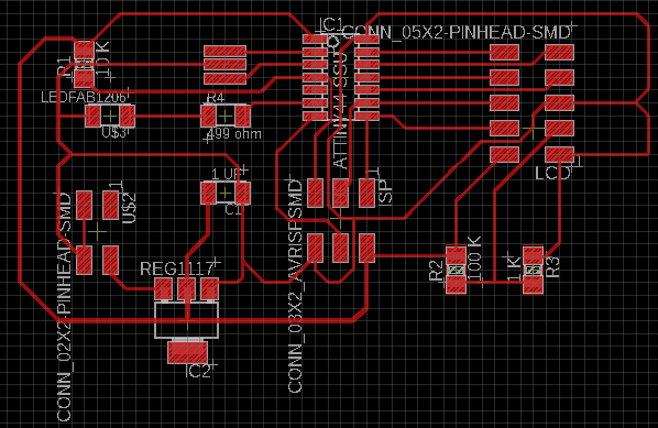
I used the board I designed for output devices week assignment and below is the board design for it :
I connect the Tx and Rx of the Bluetooth module with Tx and Rx pins of the attiny44 . and so on for Vcc and GND .
Tx of the Bluetooth with Rx of attiny44, and Rx of Bluetooth with Tx of attiny44 .
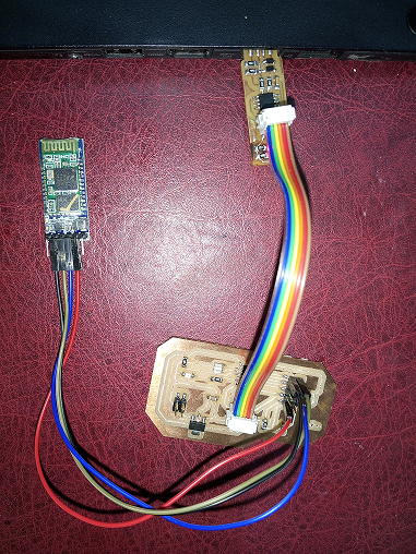
the pinout for Bluetooth HC-05 is as follows :

Now , Download “the Bluetooth HC-05 terminal” from Playstore.
for connectivity function test , I turned on the Bluetooth on my smart phone , the Bluetooth HC-05 module were detected with the name “HC-05” and it is paired with the phone with “1234” PIN number .
and then connect with the HC-05 module
enter 1 in terminal to turn on the led which is connected to pin 7 on attiny44 and enter 0 to turn off the led .
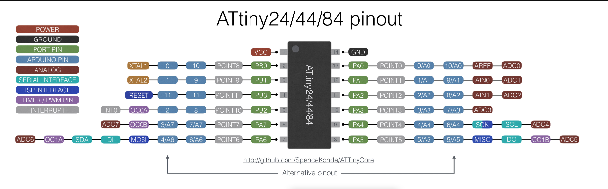
It is important to refere to the attiny44 pinout to be sure that we connect the Tx ,Rx, vcc , GND ,and led correctly.
The Code is as following :
#include <SoftwareSerial.h>

SoftwareSerial mySerial (1,0); // RX, TX

void setup() {

mySerial.begin(9600);

 pinMode(7, OUTPUT); // put your setup code here, to run once:

mySerial.begin(9600);
 }
void loop() {

  // put your main code here, to run repeatedly:
 if(mySerial.available()>0)
   {
      char data= mySerial.read(); // reading the data received from the bluetooth module
      switch(data)
      {
        case '1': digitalWrite(7, HIGH);
        break; // when 1 is pressed on the app on your smart phone
        case '0': digitalWrite(7, LOW);

        break; // when 0 is pressed on the app on your smart phone
        default : break;
      }
   }
   delay(50);
}
and here is the Heroshot vedio for it :