7. Electronics design
Group Assignment
There are three tests demonstrated in the images below :
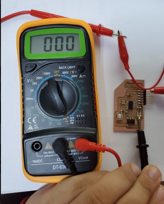
- Short circuit test:
Here we test put the props of the multimeter on VCC and GND nodes , the multimeter should not produce a beep sound if it is so ,then there is a short circuit .
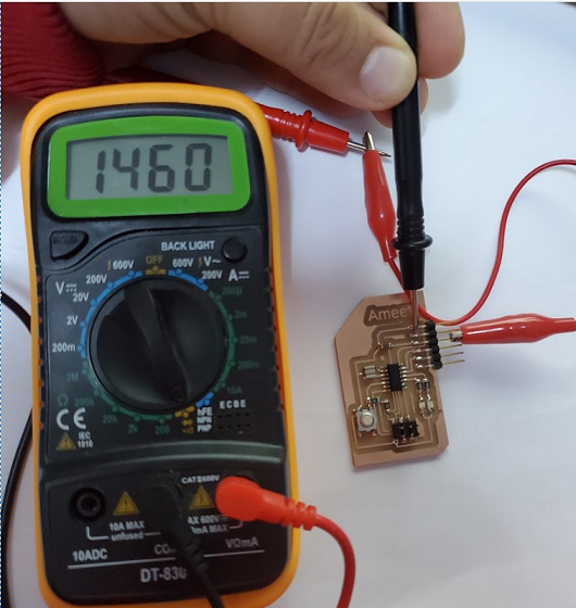
- Continuity VCC - VCC
Here we test the VCC node on FTDI and VCC node on ISP and Attiny45’s VCC node , the Beep sound must heard .
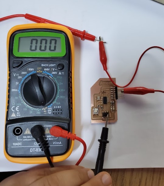
- Continuity GND - GND
Here we test the GND node on FTDI and GND node on ISP and Attiny45’s GND node , the Beep sound must heard .
Oscilloscope testing :
Oscilloscope it is an electronic test instrument that graphically displays varying electrical voltages as a two-dimensional plot of one or more signals as a function of time. Source
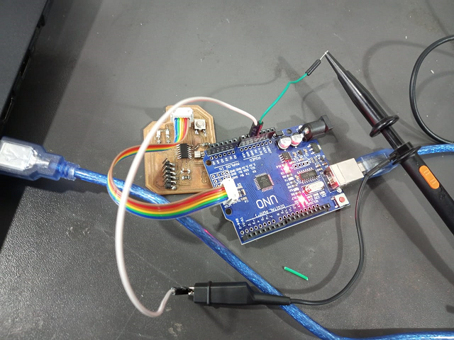
the following board is supplied with 5 volt from Arduino board as a power source , so we connect the probe (positive) to the 5v volt pin on Arduino board , and you can connect with Vcc pin on the board itself , and the negative wire of the probe will be connected to the ground of Arduino board or gnd of our board .

and here is the Oscilloscope with board connection :
and here is video for this operation :
and here is the source voltage noise signal :
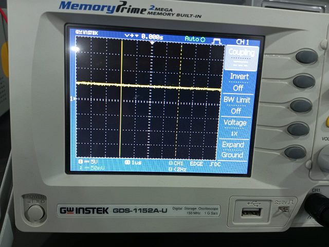
as it illustrated in the image above , we used voltage division equals to 5 volt . so every square is 5 volt .
from the image , it is obvious that we have a 5 volt signal and it is appeared that it is noisy signal .
Oscilloscope Trigger: Triggering a Scope
The oscilloscope trigger function enables repetitive waveforms to be displayed on the screen in steady fashion. The trigger enables the timebase to start its scan at the same point on each repetition of the waveform.
In this way the oscilloscope trigger enables the waveforms to be viewed in a meaningful manner, otherwise the time base would start at a random point on the waveform each time the waveform is repeated and the image of the waveform would not be meaningful.Source
as a summary ; we use the trigger function on Oscilloscope to make it easier for us to read the signal. and there are several types of triggering :
- Edge trigger (rising and falling edge)
- Pulse trigger
- slop trigger
- video trigger
- overtime trigger
- alternative trigger
Steps of using triggering (edge trigger)
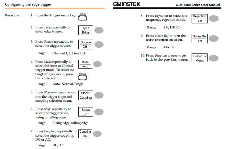
for more information to how to use the Oscilloscope please click here
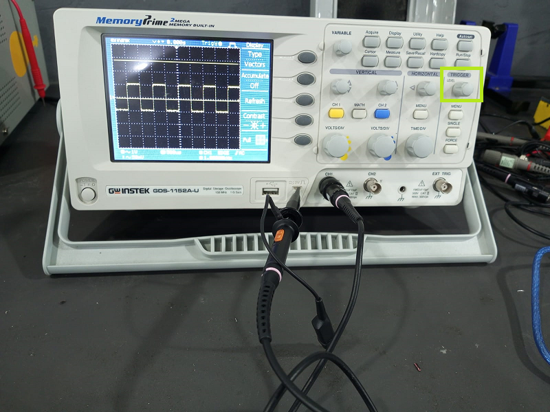
here is the signal resulting from test of the probe , you connect the probe to the oscilloscope as in the above picture then you click on single which is under the trigger knob. this will stope the wave .
here is a video :
and here is a useful link for Oscilloscope triggering :
Individual assignment :
Files
1.Download eagle library from here and extract it into ..\Documents\EAGLE\libraries
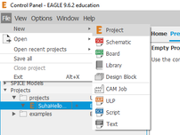
2.Open Eagle software and make new project , I name it “SuhaHelloWorld” .
3.Make new schematice by right click on project and choose new -> schematic
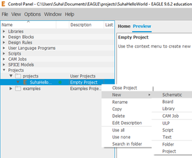
4.The schematic editor will open
5.in “schematic editor” ,click on Library menu and choose “open library manager” then select “available” tab .
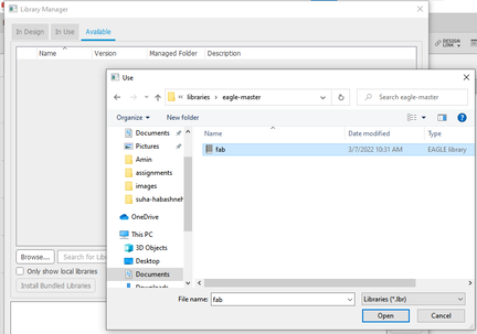

6.select “browse” then select “fab” library then choose “use” then close the “Library Manager”
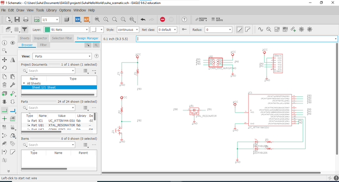
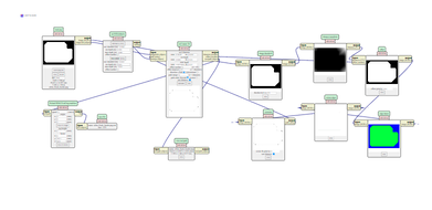
7.Now we are ready to add the components we need to design our circuit . so select “Add” to add these components to the schematic diagram and it will be like this :
8.Now we move to PCB design , Go to “schematic Editor” and choose “switch to board” from file menu and click yes for the dialogue message . 9.using “Group” tool , make a rectangle around the components and move them to the center.
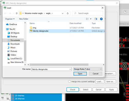
10.download the design rules to check our design from here and extract it to design rule folder in eagle.
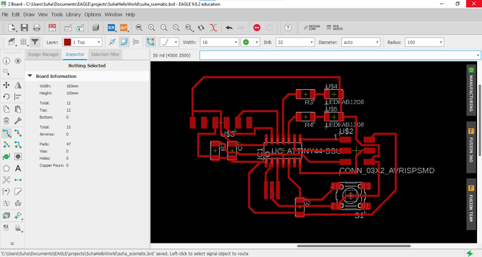
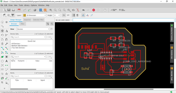
11.start to replace the yellow lines by red ones using “Route Airwire” and the result is like this :
12.now select “line tool ” and choose the “20 dimensions” layer and outline our pcb design .
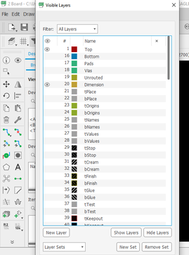
13.Go to “layer settings” ,hide all layers except Top and 20 dimensions
14.select file menu then choose export and do the following:
15.the result is like this :
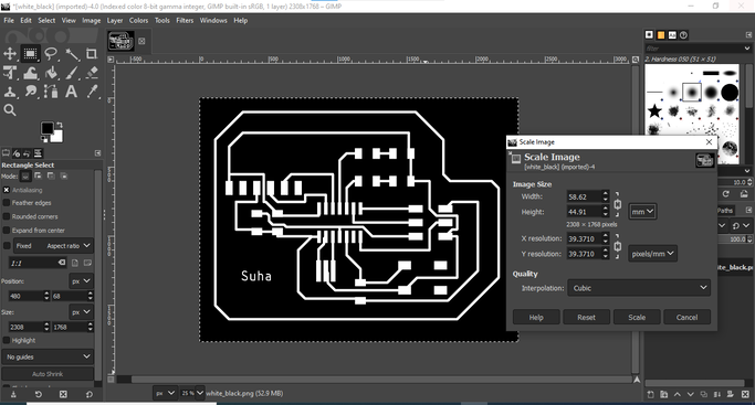
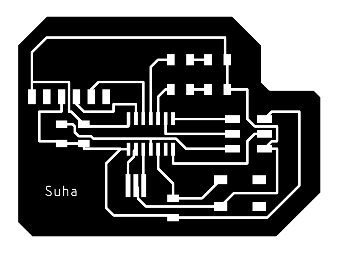
16.using “Gimp software ” , I will crop the desired area and define the interior and the outline. and the result will be like this.

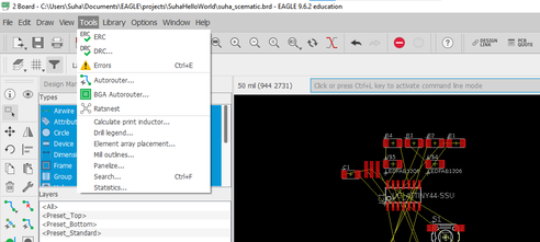
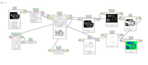
17.we use the MOD to generate rml files :
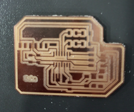
17.Now our PCB is ready to be sent to Roland SRM-20 and here is the result “Hero Shot”
-
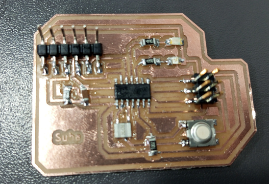
Now we will solder the electrical elements and the elements we used is as follows :
-
Attiny 44 (x1)
- R 10 Kohm (x2)
- Crystal 20 MHz
- header 1x6 FTDI
- unpolarized Capacitor 1 nF (x1)
- 3X2 ISP header
- R 499 ohm (x2)
- Green led (x1)
- Red led (x1)
- Push Button S1(x1)
after soldering the pcb produced is like this :
Programming
-
Download the C file and Make File and rename it to Makefile.
-
connections :
-
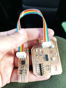
connect the ISP cable between programmer and board .
-
connect FTDI to USB port
-
connect programmer to USB port
-
Now Right click where you download the C and Makefile and select GIT Bash here .
-
type the following commands and hit enter after each command :
- make
- make program-usbtiny-fuses
-
make program-usbtiny
-
to test the board , we will upload the following code to the board using Arduino IDE , before this , we have to add the library for attiny by copying this link
https://raw.githubusercontent.com/damellis/attiny/ide-1.6.x-boards-manager/package_damellis_attiny_index.json
and paste it in additional boards , you will find it from here :
File -> Preferences ->additional boards –>paste the link –>hit OK
Go to the board manager and type “attiny” in search thin click install ,then change the board type from “Tools” an change the programmer to “ISPtiny”
Note :these steps will be covered in details in assignment of Embedded programming
#define ledpin 3 //this pin on Arduino corrosponds to PA3 on Attiny44
void setup() {
pinMode(ledpin,OUTPUT);// define the pin 3 as OUTPUT
}
void loop() {
digitalWrite(ledpin,HIGH); //send HIGH signal to the pin 3
delay(1000); // stay at high state for one second
digitalWrite(ledpin,LOW); // send LOW signal to the pin 3
delay(1000); //stay at low state for one second }
## Hero shot