5.Electronics production
Group Assignment
Roland monoFab SRM-20
As a small milling machine, the SRM-20 offers compact size and powerful functionality at an affordable price. Production of realistic parts and prototypes is made simple and convenient with a device that fits into any office, home, or classroom environment.
MOD
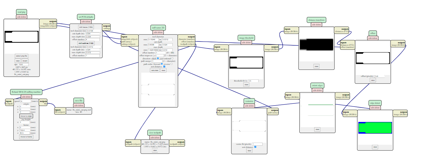
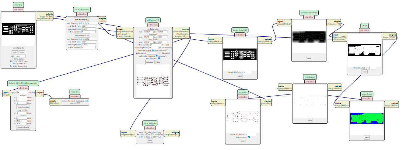
we use MOD to generate the rml files from png files which will be sent to Roland monoFab SRM-20 machine since it is the standard file format for it .
we need to do two things :
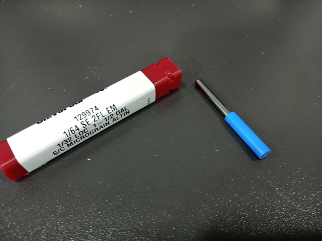
1.outbound rectangle which is the outline using a 1/64” =.4 mm milling bit
2.trace line which use a 1/32” =.8 mm milling bit
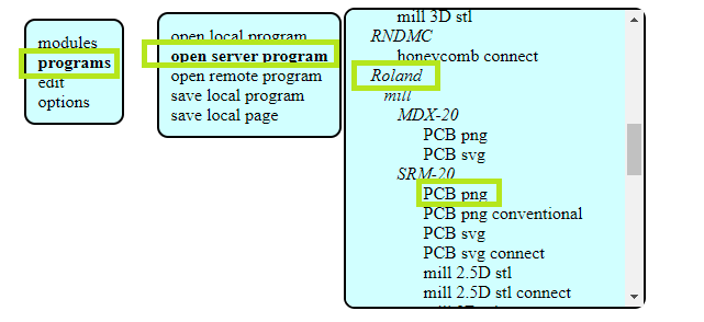
- right click on white space follow steps in picture below :
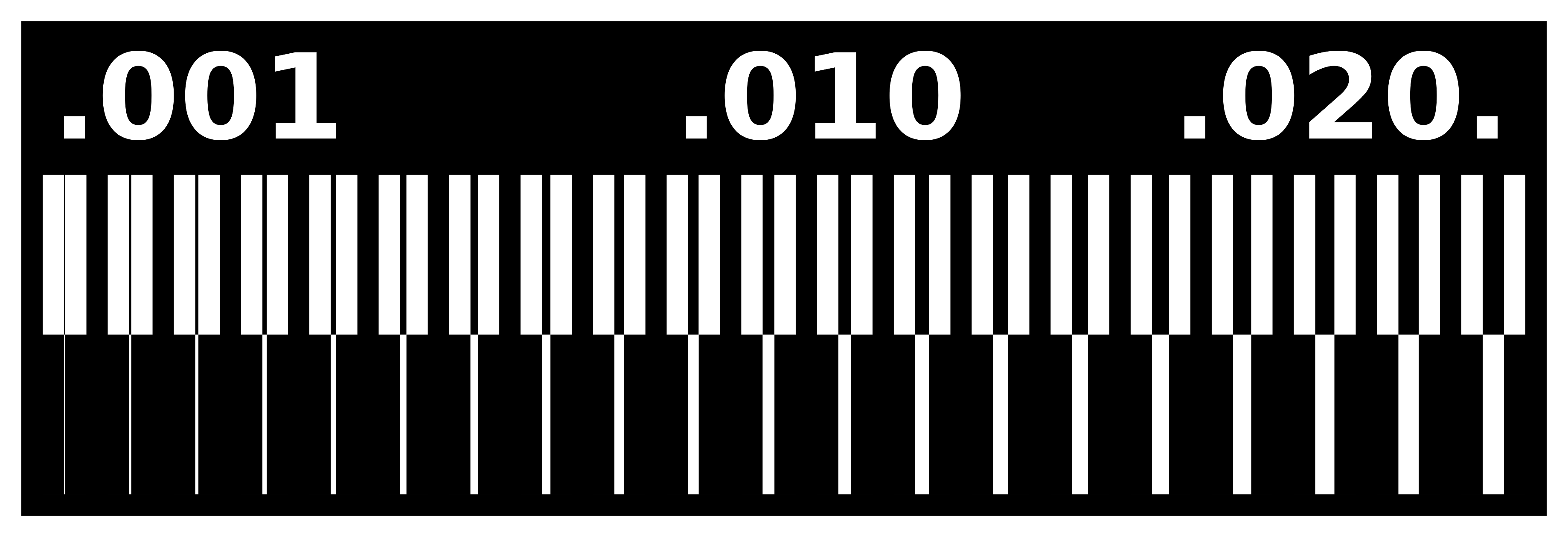
the following are the png files :

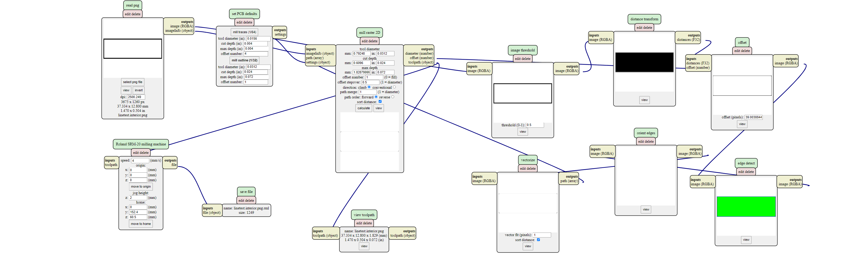
the rml files are like the following :
the outbound rectangle :
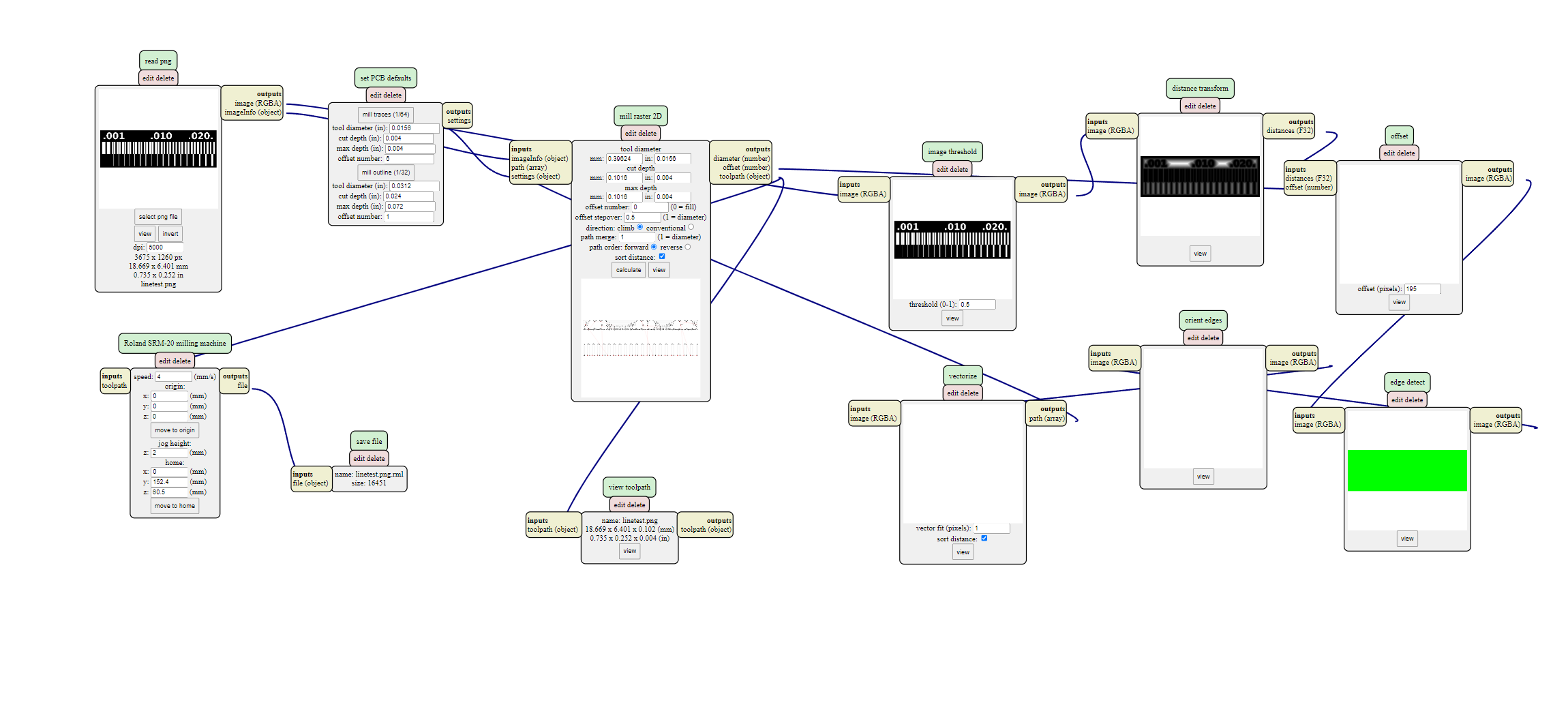
the trace :
As we our files are ready to be milled om Roland mono-fab srm-20
we have to calibrate our Roland mono-fab srm-20 to start its job :
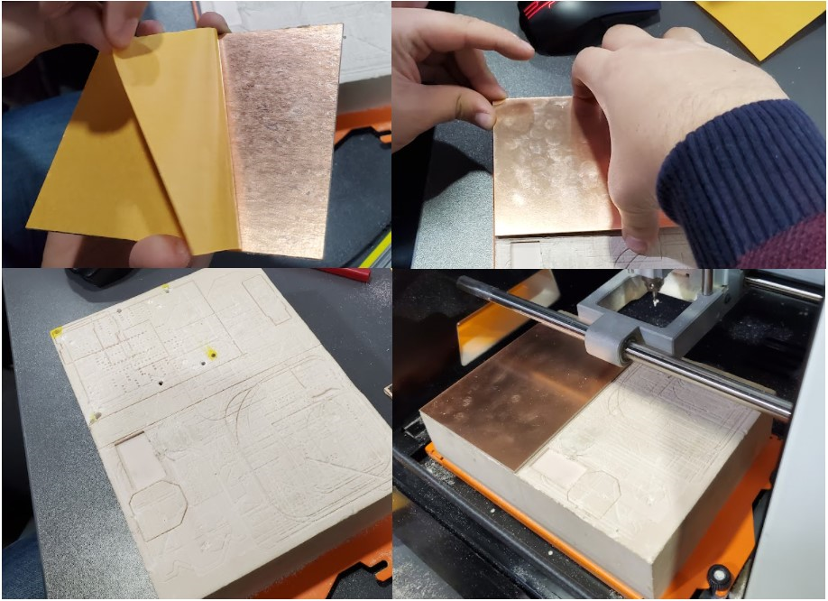
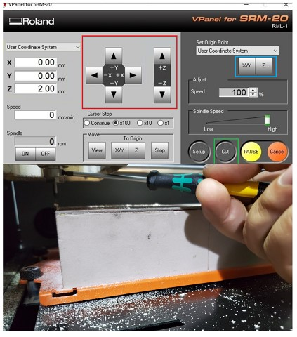
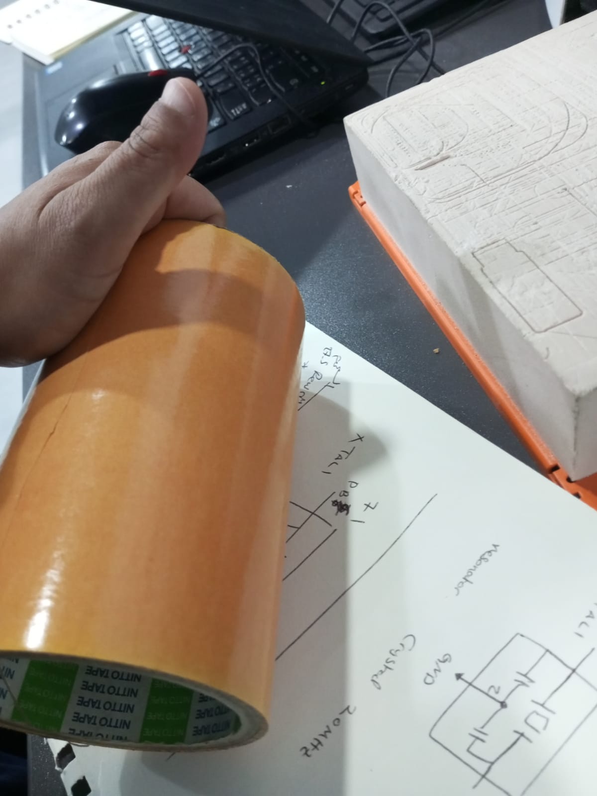
but before that we have to prepare the pcb sheet , we stick the pcb board on wood surface using adhesive sheet and make sure there are no bubbles between the board and the adhesive sheet .
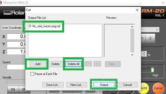
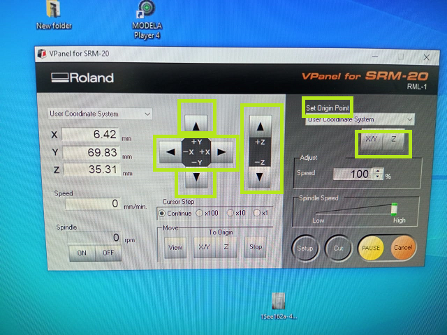
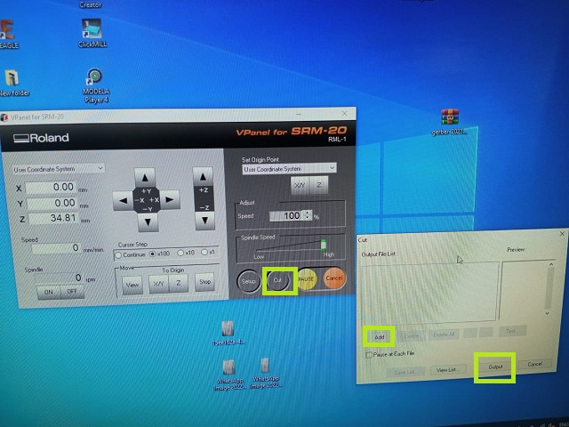
we move to VPanel software and calibrate the machine (x,y and z)
now select the file we want to mill and choose output
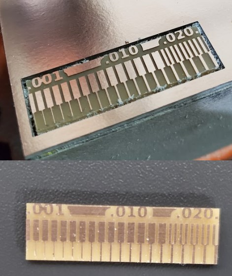
the result is like this :
Individual Assignment :
Files
Repeating the same steps in dealing with the files of png and rml files that are sent to Roland SRM-20 .
I used the png files and rml files shared by Colleague Aziz Wadi and they are already found at here
Basically ; the first step in Electronics Design and production is to know which components do we need to assemble the circuit , so we need the following components :
- 3x2 isp header(1x)
- ATTiny 45(1x)
- Resisitors with the values of :
- 499 ohm (x2)
- 1 Kohm (x2)
- 49 ohm (x2)
- Zener diode 3.3 v (x2)
- LEDs:
- green led (x1)
- red led (x1)
- capacitor 100 nF (1x)
based on this we can design the circuitSource :
The schematic design :
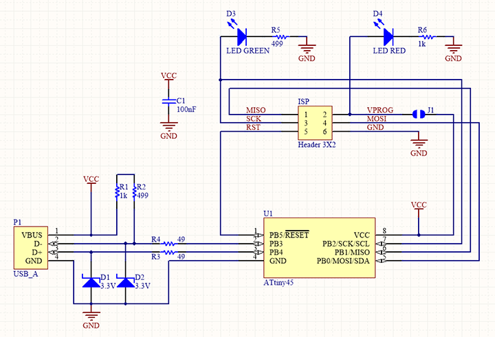
The board :
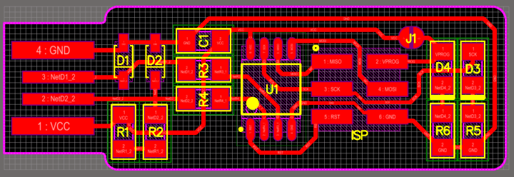
after producing the board file , we can export the image of board and go to the GIMP software to make the traces and outline cut images to be sent to the MOD site and generate .rml files
Traces image:
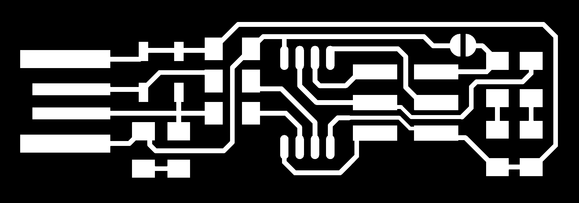
Outline cut image :

MODs Process :
- upload the png file for traces image or cut image then choose the bit 1/32 or 1/64 , make the origion for x,y and z to be 0,0,0 , and jog z is 3 , make a “save module” then click on calculate ,this will automatically download the .rml file.
Now , we have the .rml files , we send them to Roland SRM-20 to be milled as the process that is mentioned in the Group assignment.
Stuffing and soldering
Prepare the board to be milled
- fix the board you want to mill using adhesive sheet that is dedicated for this purpose .
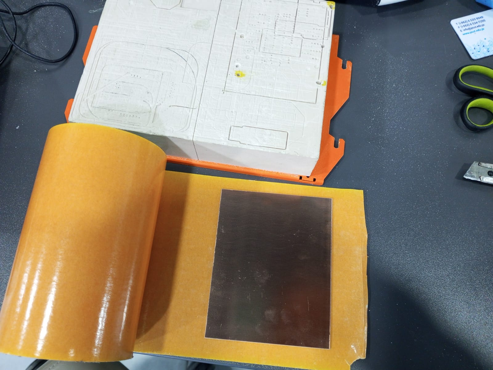
- peel off the sheet then make sure it is stick firmly to the wooden piece , you can use the roll of adhesion material it self , push down .to make sure it will never move when you start the milling.
-
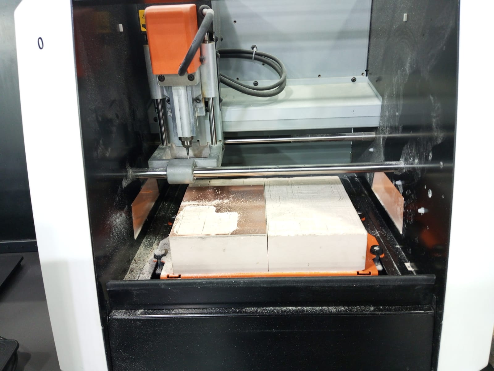
Now fix the wooden piece into the Roland machine using screws.
-
Move to the calibration part .
Machine calibration
- Now we move to the Roland Desktop milling machine Roland SRM-20 and start to calibrate the x,y and Z axis using the VCarve software that is the official software for Roland SRM-20. So for X-axis we press on left and right arrow , for Y-axis move the Up and down Arrow , and for Z-axis press on the up and down arrow after getting the right calibration for each of x,y and z you should press on the button that is under the “set origin” part .
- press on cut -> add -> choose the file you want to mill for traces or cut . then hit output .
- the machine will start milling .
- we use the 1/64 bit for milling the traces . and we use 1/32 to mill the outline or cut lines .
- after assembling each one of bits , we have to re-calibrate the machine axis.
Soldering
- when the Roland SRM-20 finishes the milling , take the usbtiny board and start the soldering process . and test the board first to make sure that all traces is good and there is no contact between traces .and no short circuit.

note :the above picture is for clarification only , I used another soldering kit but I couldn’t be able to capture a photo for me when I was doing the soldering)
but there are two hints when you solder : 1. try to heat the trace before applying the paste on it . 2. put the paste on to the soldering head then put it on the position you want to solder.
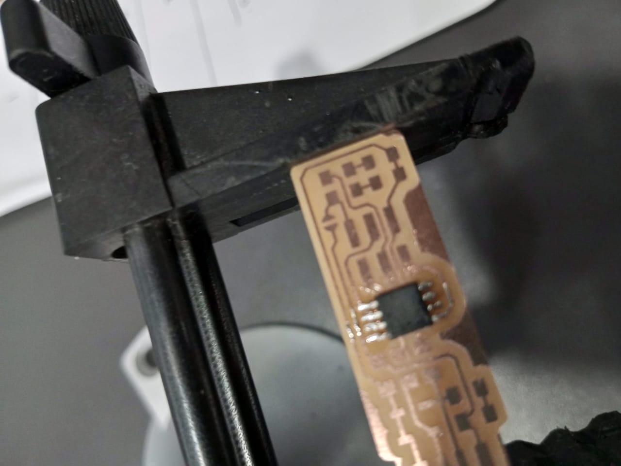
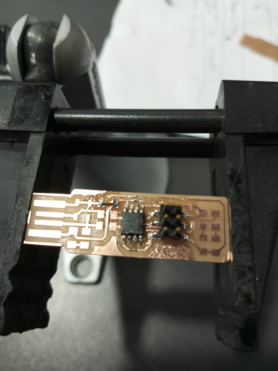
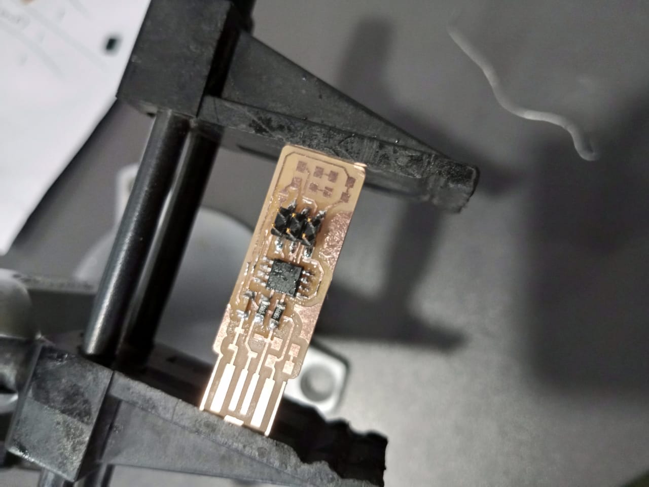
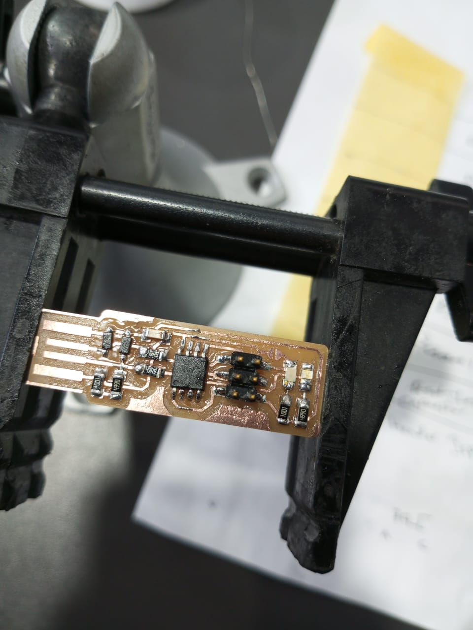
the fabtiny usb after milling and soldering :
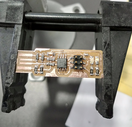
board test :
I tested the board using Multimeter , put the multimeter to buzzer mode , then touch the vcc pin on board with vcc board , and touch the GND pin on the board with GND . and check all the traces , if there is a beep , then there is short circuit otherwise there is no connection between Vcc and GND which is good .
now check vcc - to - vcc and make sure you hear the beep that indicates the trace is connected from end to end
also check GND - to -GND , make sure you hear the beep that indicates the trace is connected from end to end.
Hero Shoot :
Programming
we need to download the following programs : 1. The Atmel GNU Toolchain 2. GNU Make 3. avrdude 4. Zadig
Steps of programming : 1. Download the The Atmel GNU Toolchain and extract it to C:\Program Files .
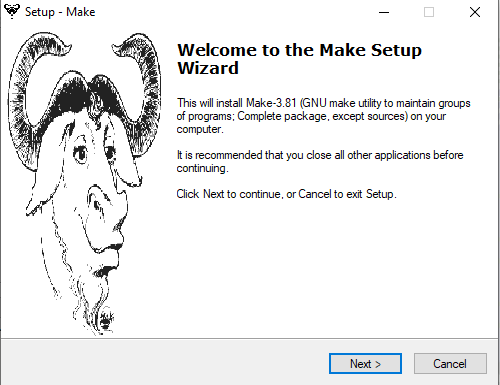
- Download and install GNU Make , click Next , accept the agreement , choose where you want to install the make software, finally select install then finish.
-
Download and extract avrdude to C:\Program Files
-
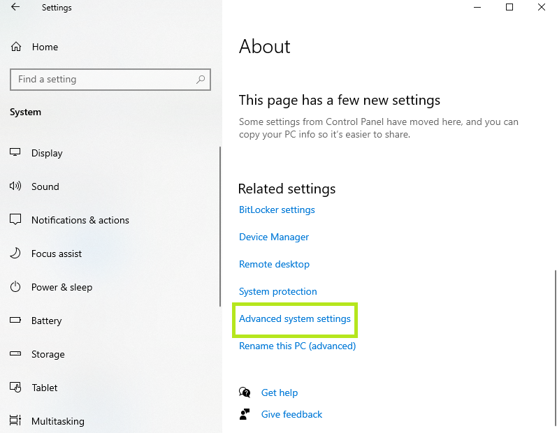
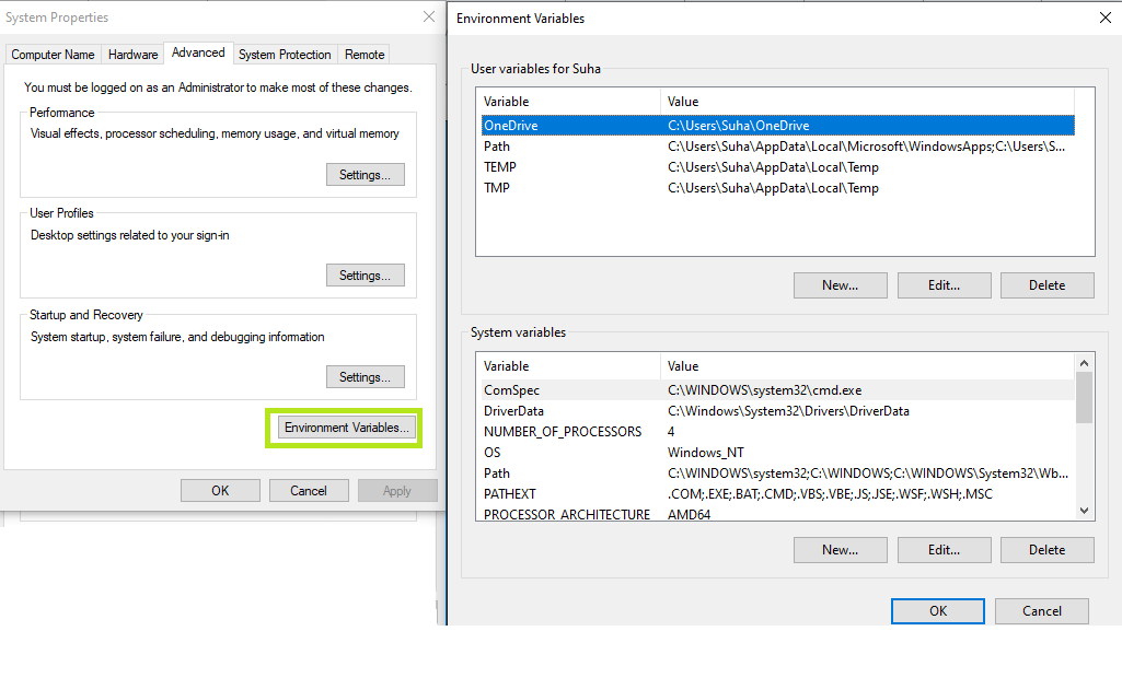
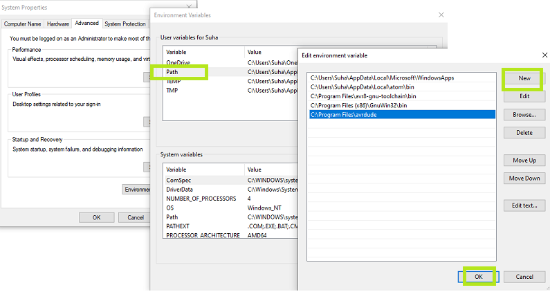
Updating the path Go to control panel -> System->about -> advanced system settings
- Installing the driver for our programmer :
This is done using Zadig , open it then plug in the programmer , and select the “USBtinySPI”,then click on install driver .
Path check :
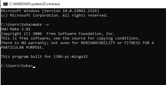
- Open CMD terminal and print make -v
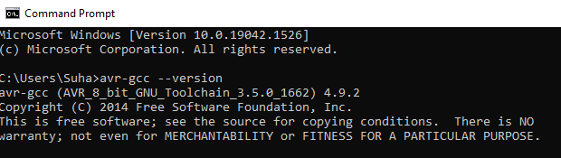
- Type avr-gcc –version and press enter. You should see:
avr-gcc.exe (AVR_8_bit_GNU_Toolchain_3.5.4_1709) 4.9.2
… and so on.
Problem and fixes:
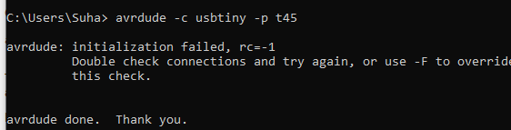
- Connect your programmer to a USB port and type: avrdude -c usbtiny -p t45 and press enter. You should see:
avrdude.exe: initialization failed, rc=-1 …
This means that avrdude successfully found your programmer, but failed to talk to a target board (expected because we don’t have anything connected to the programmer right now.)
If instead you see:
avrdude.exe: Error: Could not find USBtiny device (0x1781/0xc9f) check your USB driver installation (the Zadig steps).
If you get a “command not found” error, check your installation of avrdude and your path variable.
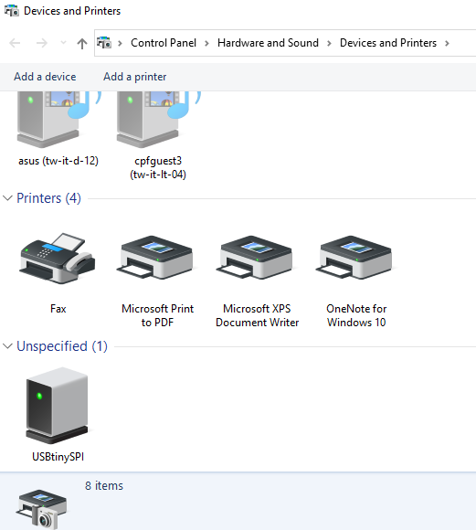
to check that the USB is installed well
go to control panel -> devices and printers
Programming the FabTiny ISP
The procedures done by using a programmed FabTiny ISP of my colleague Amin .
-
Download the firmware source code and extract it .
-
Open CMD (command terminal) and cd into the source code directory.
-
Right click and select “Bash here”
-
Type “make” then enter
-
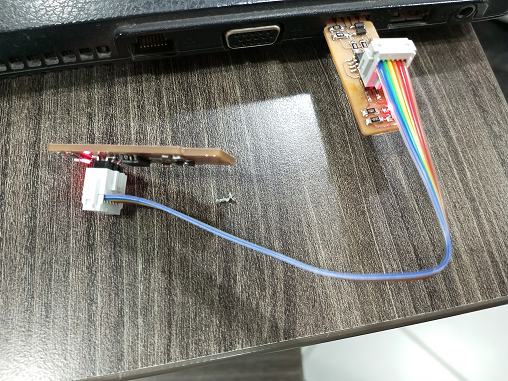
Connect the ISP header of programmer usb to ISP header of FabTiny USb that we want to program
-
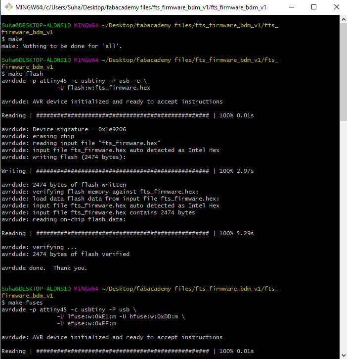
Type “make flash”
-
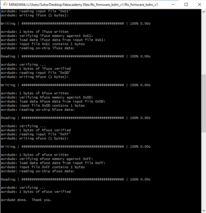
Type “make fuses”
-
Type “make rstdisbl” , this command once is executed , the targeted usb can not programmed again.
-
Remove the jumpers .
Hero Shot
I used the following tutorial , it helps me a lot .
in addition to this useful guide.