13. Input devices
-
Add an input device to a microcontroller board you’ve designed and program it to do something.
For this week I decided to design the board for my final project. With the help of Antonio, our FABolous instructor, I managed to design it.
Since I wanted to use this week’s assignment to understand better my final project, I decided to design a board with My final project, indeed, will involve many servo motors and I need to start playing with them in order to be able to do what I have in mind.
A few words on Input devices
Input and output signals can be analogue or digital. An analogue signal can take on any value (within a known range). With considerable simplification, all physical quantities that can be measured in the environment can be thought of as ‘analogue’. A digital signal can only assume two states (High/Low, 1/0), corresponding to two conventional voltage levels (e.g. 5-0V). With this simplification, we can think of all information exchanged between logical components (microprocessors, memories, network interfaces, displays, etc.) as ‘digital’. In order for an analogue signal to be read and processed, it must be sampled, i.e. converted into a bit sequence expressing its amplitude. A digital signal is immediately ‘readable’ as soon as its level (Hight/Low) has been discriminated.
- Of the analogue signal, one is interested in reading the instantaneous value, appropriately sampled.
- Of the digital signal, only the high or low state needs to be known.
In order for the microcontrolelr to recognise whether an Input or Output signal is present on the PIN we are referring to, the digital PINs must first be set to input or output mode. This is done via pinMode.
Example: pinMode(13, INPUT);
sets PIN 13 to INPUT mode. This means that a digital signal can come in of PIN 13 and can therefore be either High or Low. (In practice electronically a voltage may be output that will only take on two values, 5V or 0V).
Unlike a Digital Input which can take on the two values LOW and HIGH which correspond to a null (GND) or positive (+5V) voltage respectively, with an ANLOG INPUT it is possible to read voltages between 0 and +5V. The analogRead() function receives as a parameter the number of the ANALOG PIN to be read and returns an integer number by assigning it to a variable. The integer number returned is between 0 and 1023. This means that the input analogue signal is sampled with a resolution of 10 Bit (2^10=1024), i.e. by dividing the maximum voltage (+5V) applicable to the input by 1024 we obtain a unit of 4.9 mV (the maximum resolution expressed in Volts).
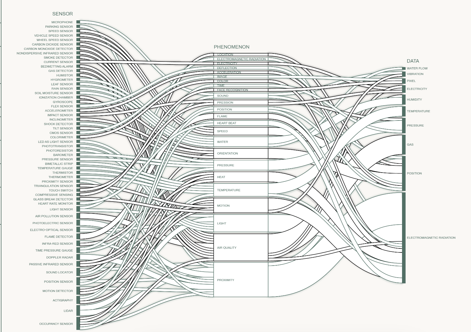
Any quantity suitably transformed into a voltage can be read: Temperature: temperature sensor Rotation: potentiometer Light intensity: photoresistor Distance: infrared sensor Inclination: accelerometer
Here I put a diagram I did for my thesis with all the sensors
In this assignment, I will use a potentiometer, which measures rotation. A potentiometer acts like a voltage divider: variable resistance, allows variable voltage.
👩🏽🍳 EAGLE
This board will include an ATmega328, four servo motors and two leds. Here is the pinout of the ATmega328.
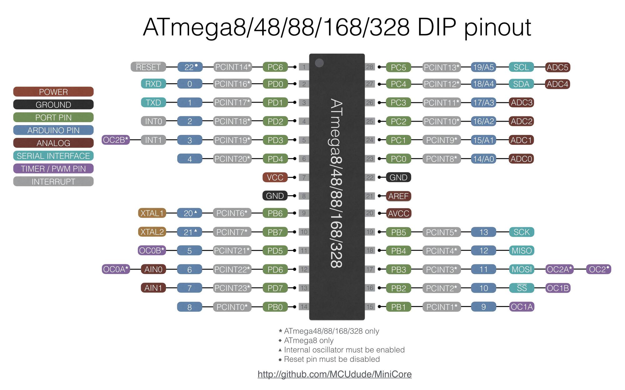
This however was not the shape of my atmega328, so I also used this pinout to have a better visual representation of my board.
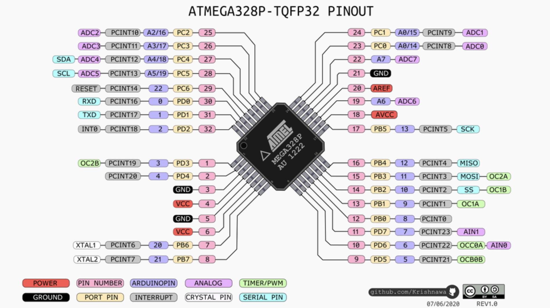
You can see in the pinout that the ATmega328 has enough PWM pins, which I needed in order to connect the servo motors. PWM pins (in the pinouts are called TIMER/PWM) stand for Pulse Width Modulation pins. They are pins that have the ability to getting analog results with digital means. Digital control is used to create a square wave, a signal switched between on and off. This on-off pattern can simulate voltages in between full on (5 Volts) and off (0 Volts) by changing the portion of the time the signal spends on versus the time that the signal spends off. The duration of “on time” is called the pulse width. To get varying analog values, you change or modulate, that pulse width. If you repeat this on-off pattern fast enough, the result is as if the signal is a steady voltage between 0 and 5v controlling the speed of the motor.
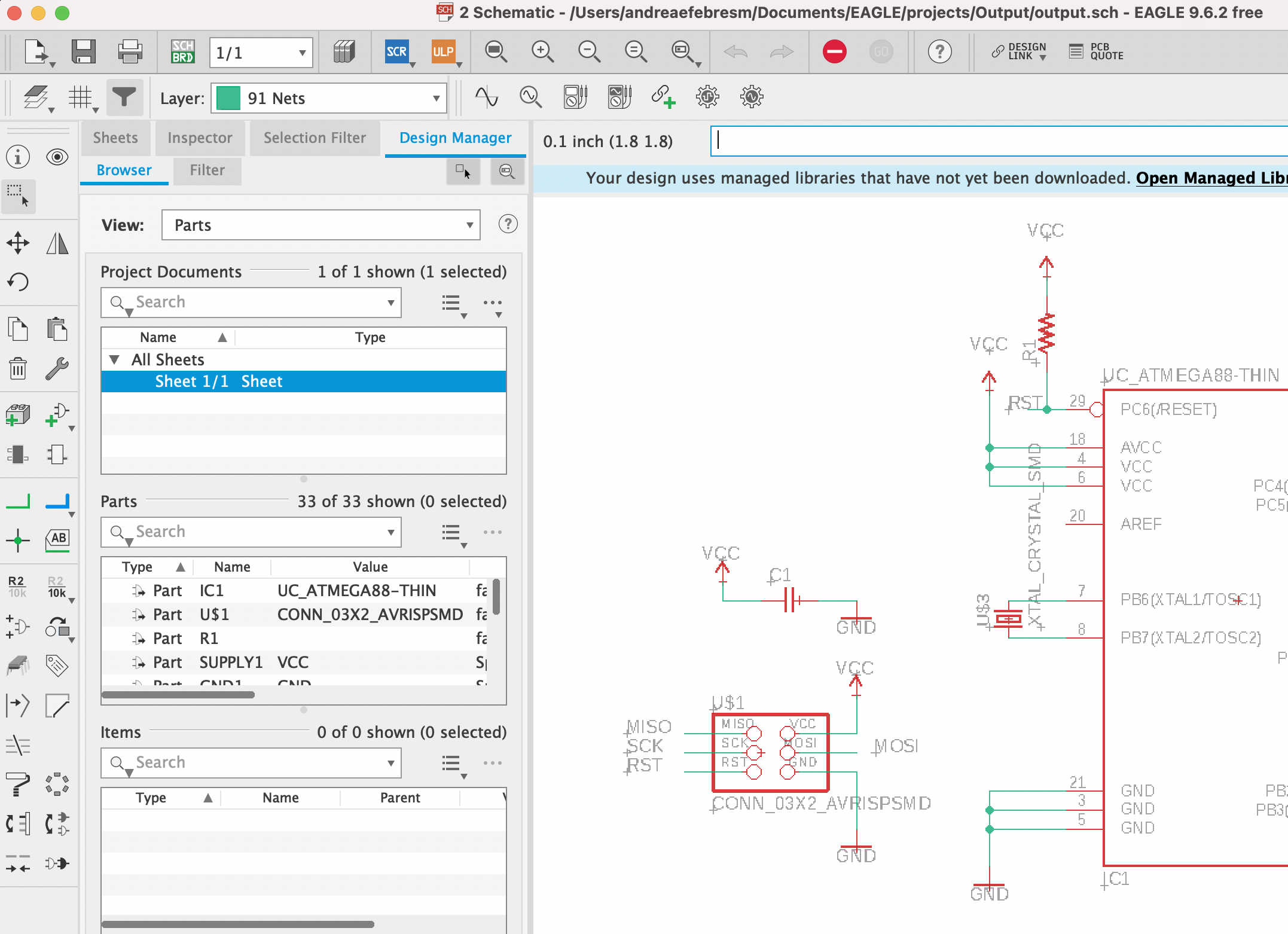
👩🏽🍳 SCHEMATIC
I started directly to do the schematic by adding the atmega328, whose correct format is UC_ATMEGA88-THIN. Following this step, I added the ISP (named CONN_03X2_AVRISPMD) and a cristal (XTAL_CRISTAL_SMD). I directly connected these components to the attiny looking at the pinout, therefore I connected the cristal to pins PB6 and PB7 since they are XTAL1 and XTAL2. As far as ISP is concerned, I connected the MOSI, the MISO, the SCK and the RESET pins of the ISP to the directly correlated in the ATmega328. I also put a capacitor of 1uF and a pullup resistance of 10K ohm connected to the reset pin.
For the sensor color, I added 8 pads as follows:
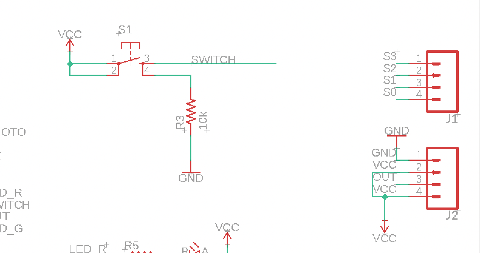
I added also an RGB LED to play also with it in this assignment and I also added one LED that lights up when the board is connected and one controlled by the microcontroller. To these LEDs I connected 200ohm resistors. The led that can be controlled by the atmega328 is attached it to the PB2 pin, indeed, while the first led is only attached to VCC and GND.
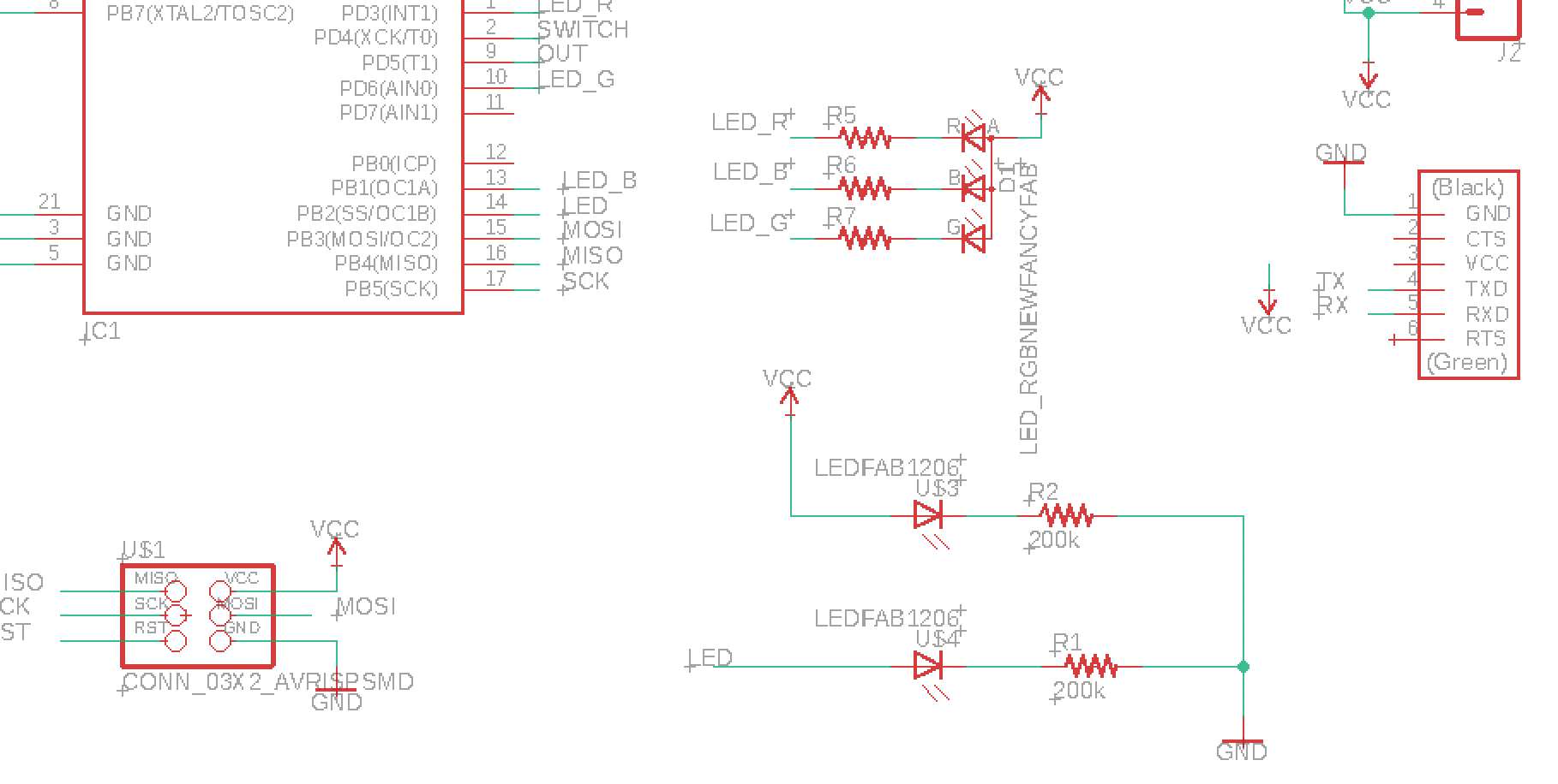
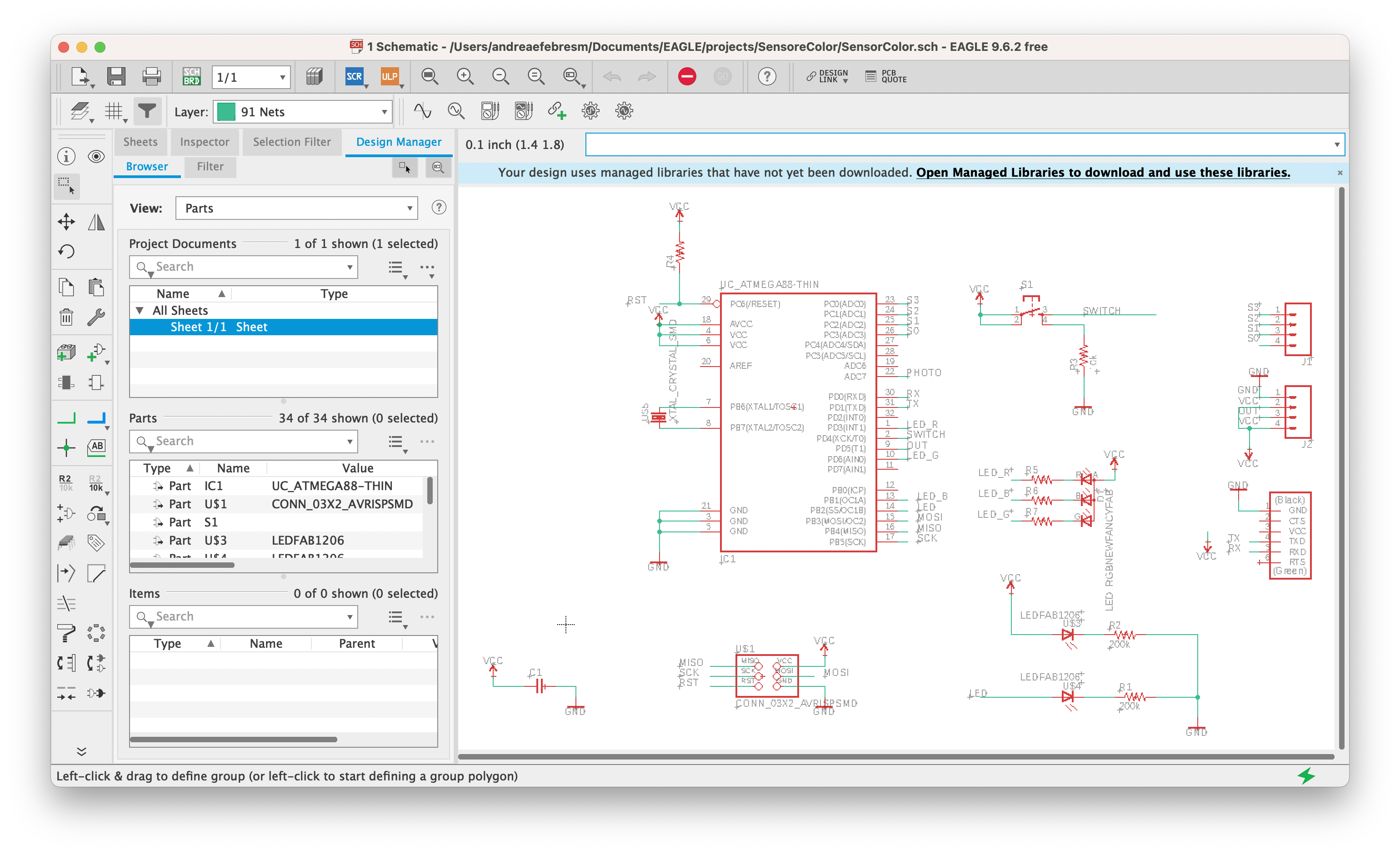
Eventually, this is the final schematic:
👩🏽🍳 BOARD
I switched to the board file in eagle and I started to arrange the components in the space. I tried with an autoroute first (with auto command) but I could get only 88% routes. So I started to arrange in the space the components again, trying to find a solution without usign 0ohm resistors but in the end I decided to use one (which you can see in the schematic above). I then changed layer (in the top left corner there is the layer panel) and selected the 20 Dimension layer, which is the yellow one. I wrote line in the command bar and drew a line as a border for my board. Here is the board with the routes (with 0.5mm Clearance and 16mil width in the Design Rules).
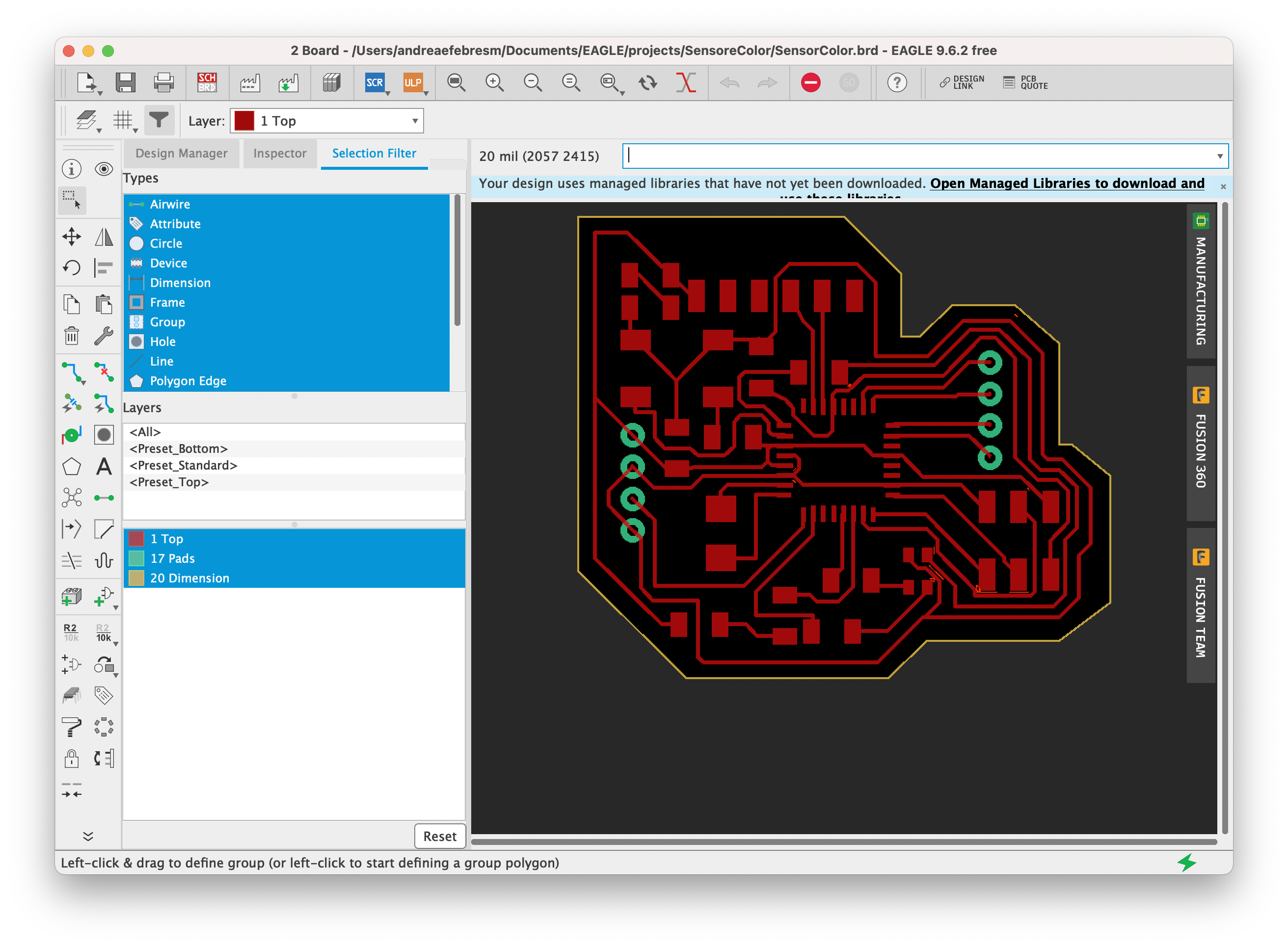
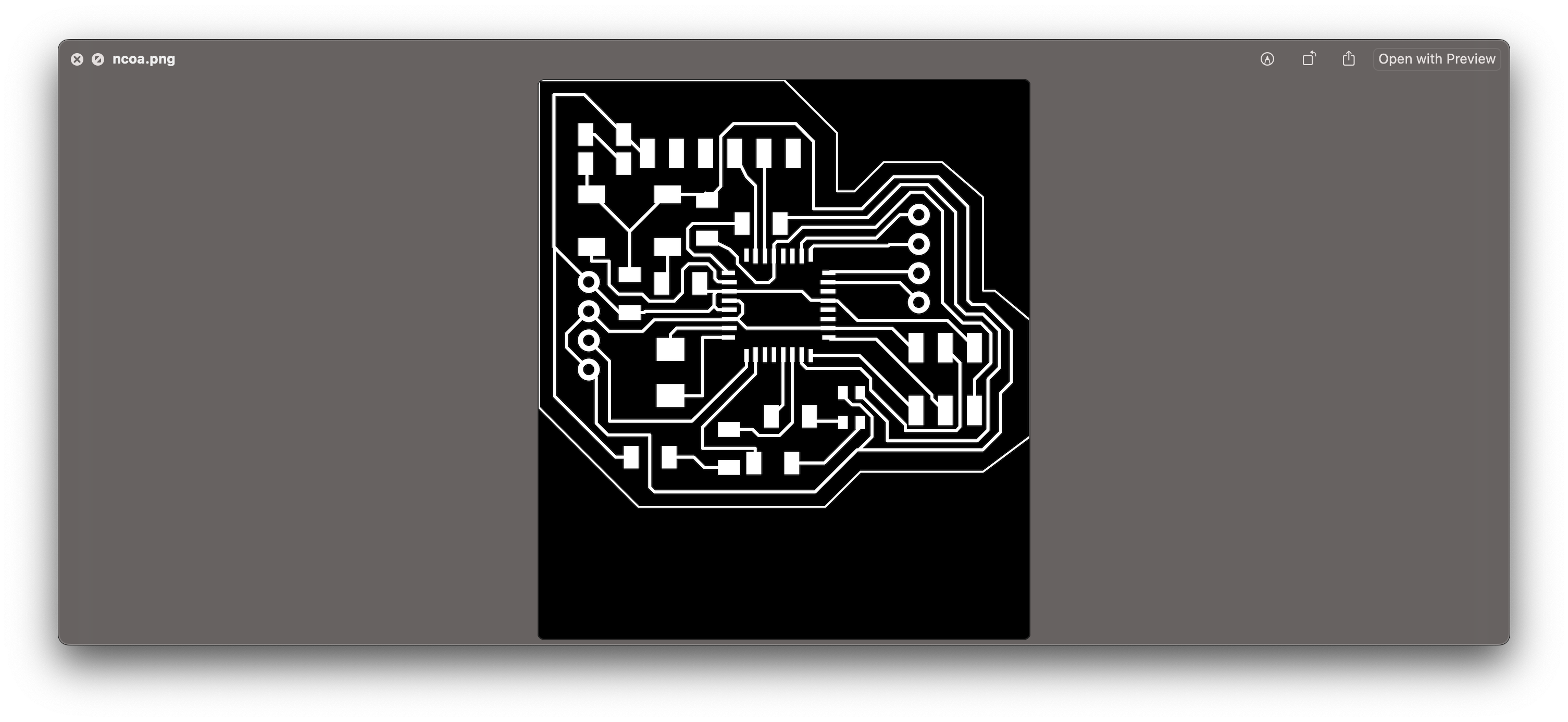
I went to the layers panel and selected all the layers (with Command+A) and then Hid them all. Then I clicked on Top, Pad and Dimensions to show only these layers for export matters. Lastly, I zoomed out and selected the yellow rectangle that made my black background and deleted it because if you don’t delete it, then you will export the whole rectangle and not only the board.
I then went to File > Export > Image and I browsed to my folder to save the image. I selected monochrome and set the dpi to be 1000. I saved the image that is this:
🫐 FabModules
Before going in fab modules, I opened the png in Photoshop and separated the traces from the outline.
I checked that the dimensions of the image were correct since EAGLE has a bug with MacOS and exports the image at the double of the size.
I then did the same process I explained before here and started milling as explained here.
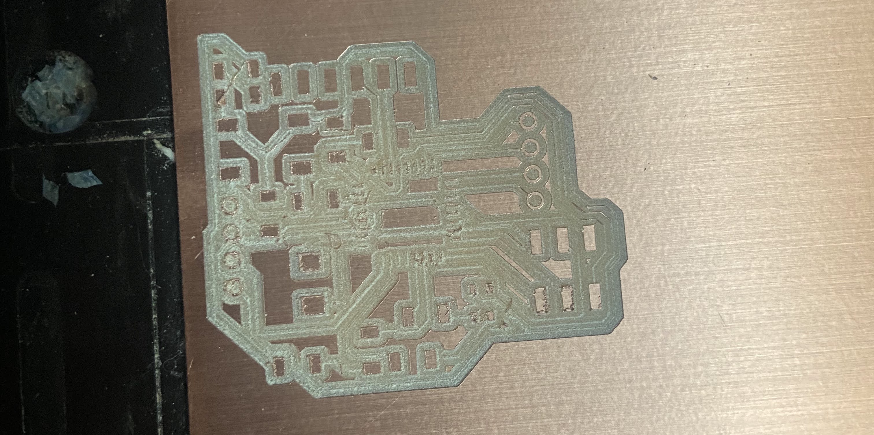
As you can see, it did not turn out well. The traces are almost faded and not present at all. What I messed up, is of course the calibration: I went too deep and ruined the pcb. Therefore, I decided to do this assignment later and I did it with my All-in-One-Board I described in Electronic design.
🪁 Arduino IDE
In order to program my board, I needed to prepare the pipe.
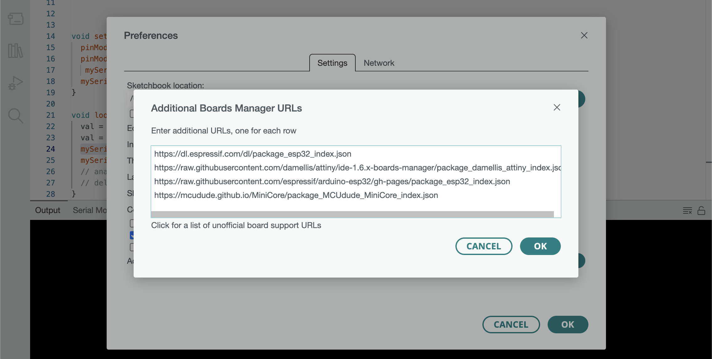
I proceeded opening arduino ide and added the board processor for ATTINY. I did so by opening the preferences in Arduino IDE
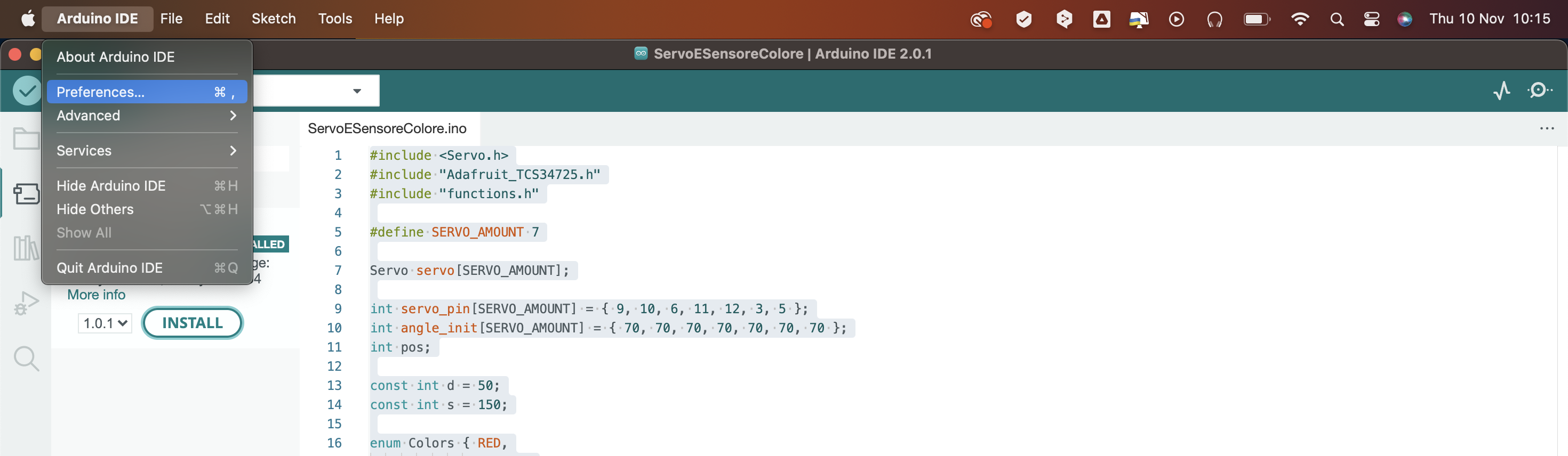
and clicked on Additional Boards Manager URLs.
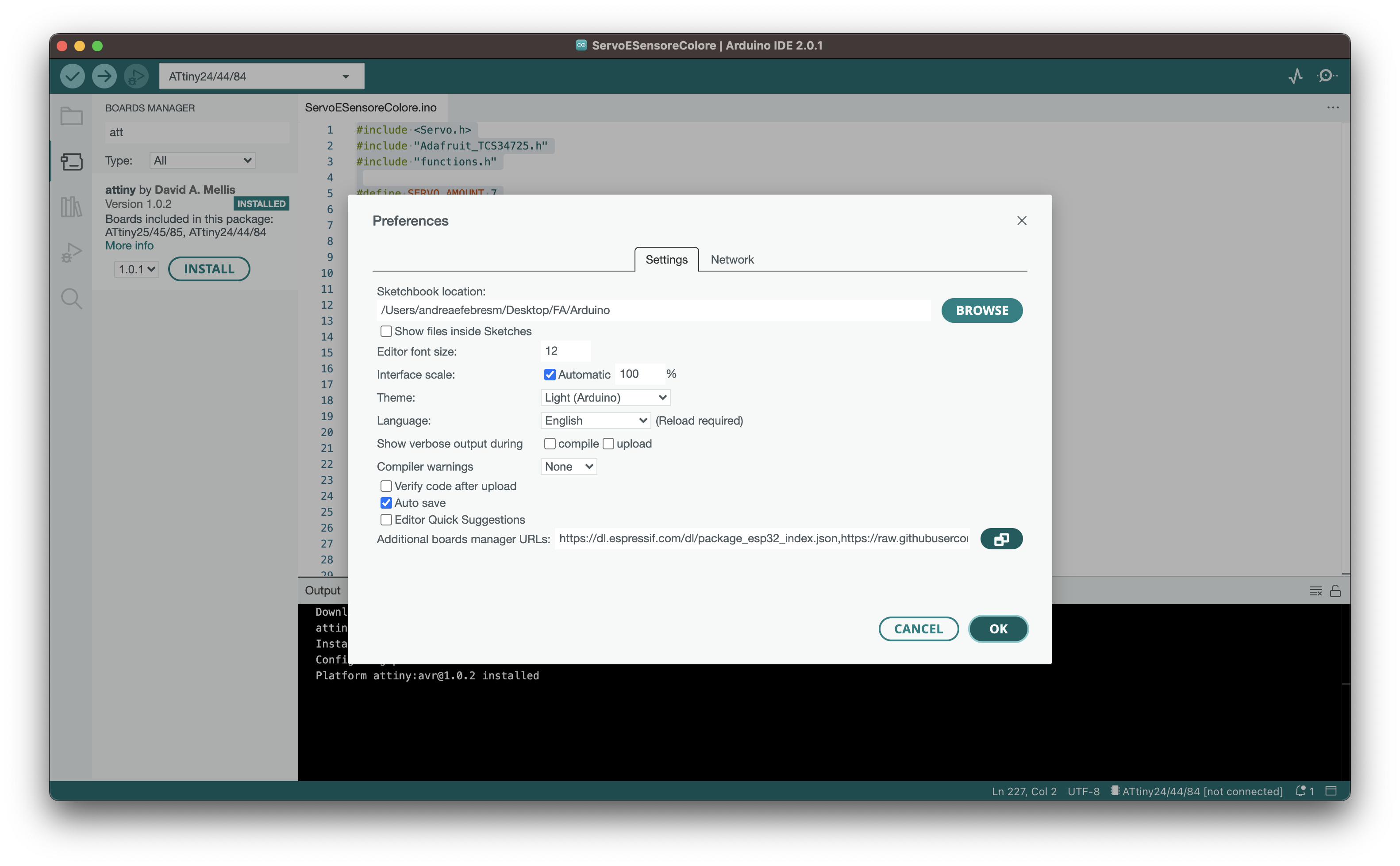
I then pasted the following url.
https://mcudude.github.io/MiniCore/package_MCUdude_MiniCore_index.json
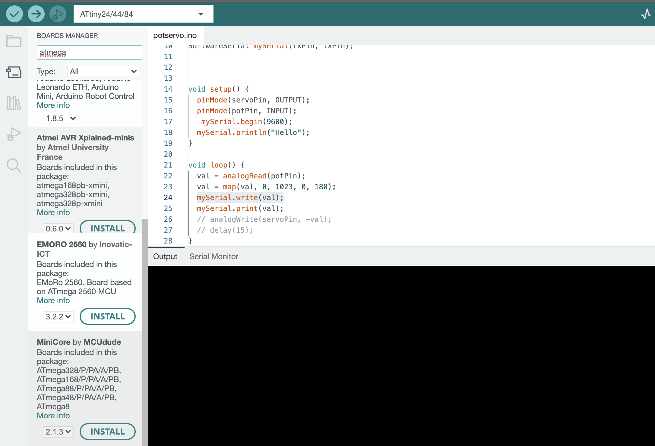
I then could open the board manager that you can find in Tools > Board > Board Manager (or using the shortcut SHIFT+COMMAND+B in MacOS)
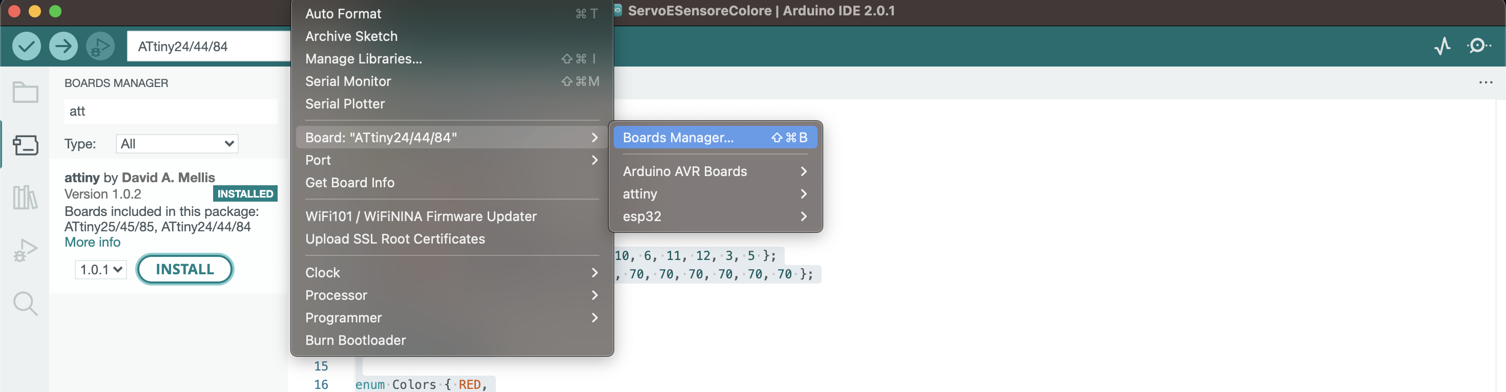
and clicked on INSTALL.
Now that I have the board installed, I can select it in BOARD as follows:
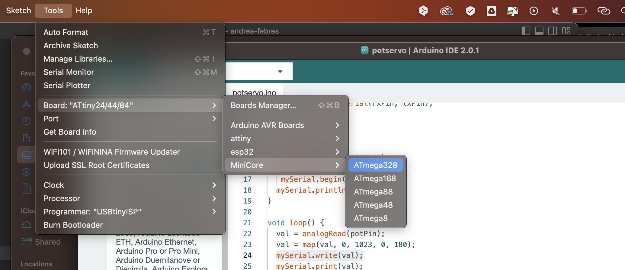
And eveything is ready to be moved!
🏷️ The code
I wrote a very simple code that made the servo motor move accordigly to the potentiometer. Let’s disclose it for the newbies, like me.
🎀 Declaring my variables
First off, I have to declare my variables. In this case, I declared the pin for the servo and the pin for the potentiometer. I looked at the pinout, of course, to see which pin was what. I then declared an int variable named val for the angle of my potentiomenter.
int servoPin = 8;
int potPin = 7;
int val;
📪 Setup
In the setup part, I attached both the servo and the potentiometer to their relative pins with pinMode and of course I set the servo as an OUTPUT and the potentiometer as an INPUT.
void setup() {
  pinMode(servoPin, OUTPUT);
  pinMode(potPin, INPUT);
}
🥨 Loop cycle
In the loop cycle, I first of all assigned the val variable to an analogRead of the potentiometer in order to see the value of my potentiometer.
val = analogRead(potPin);
Then I used the map function to convert the values of the potentiometer, that go from 0 to 1023, in an angle from 0 to 180. The map function re-maps a number from one range to another. That is, a value of fromLow would get mapped to toLow, a value of fromHigh to toHigh, values in-between to values in-between, etc.
val = map(val, 0, 1023, 0, 180);
I then proceeded in making the servo rotate by assigning val to analogWrite.
analogWrite(servoPin, val);
I added a delay of 15milliseconds just to give the board and components time to process.
delay(15);
I compiled this code with COMMAND + R to see if there was any error in the code. Since everything was fine,
I proceeded to upload the program to the board. To do so, I did the following steps:
- Select the port
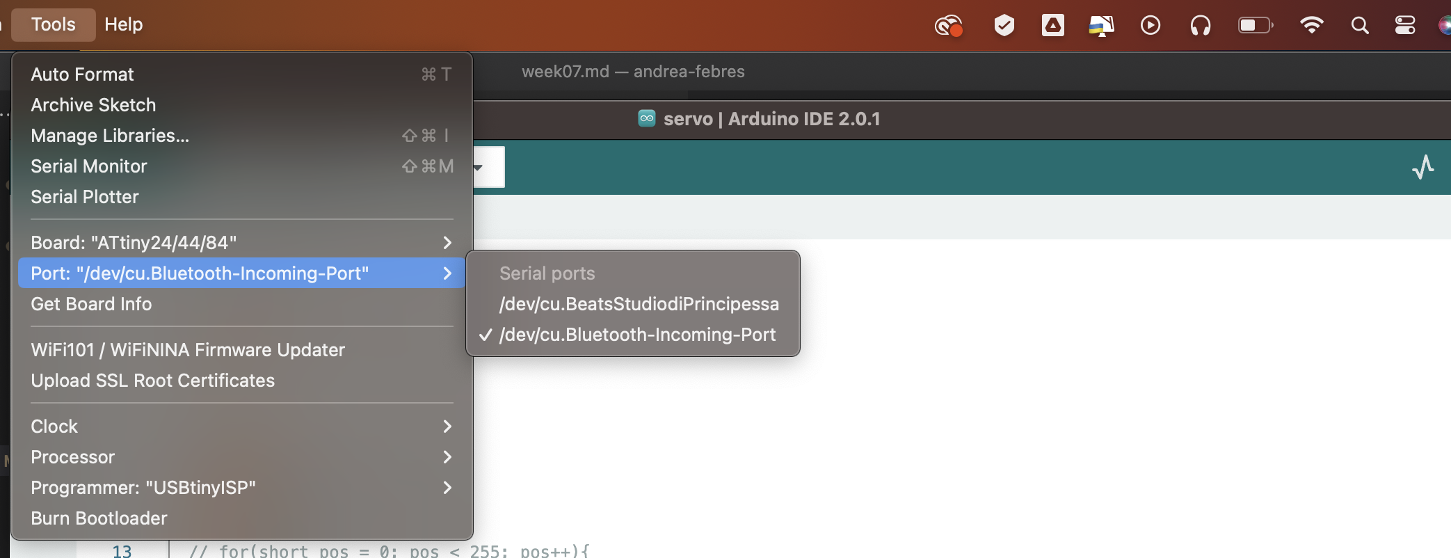
- Select the clock (the attiny44 has 8MHz)
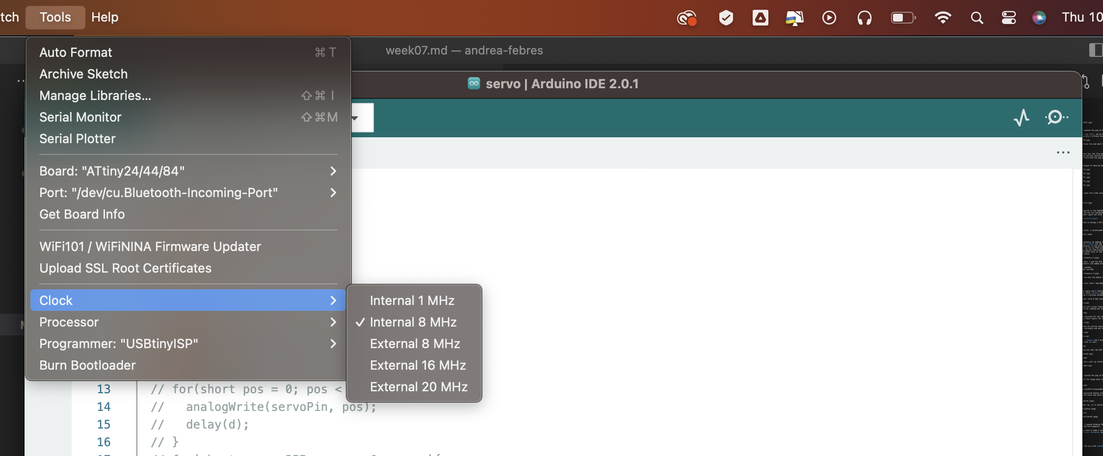
- Choose the processor (ATtiny44)
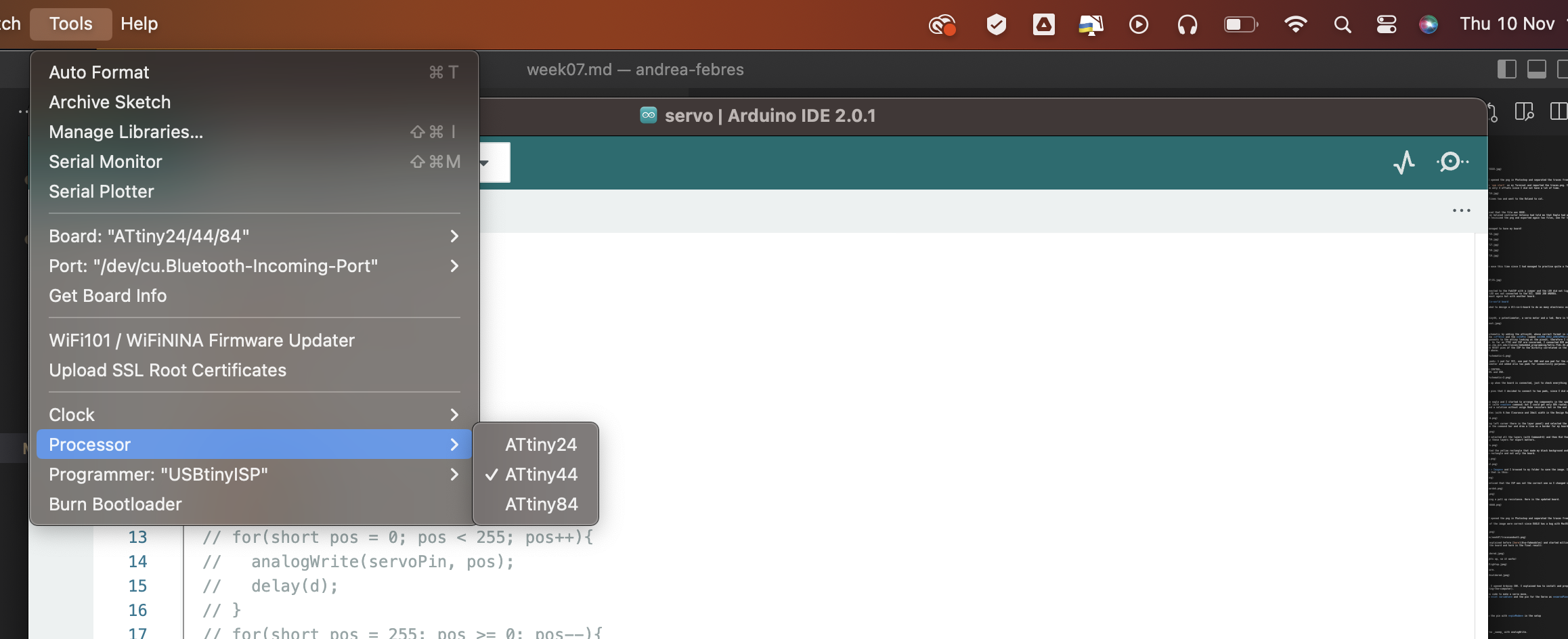
- Choose the programmer (USBtinyISP)
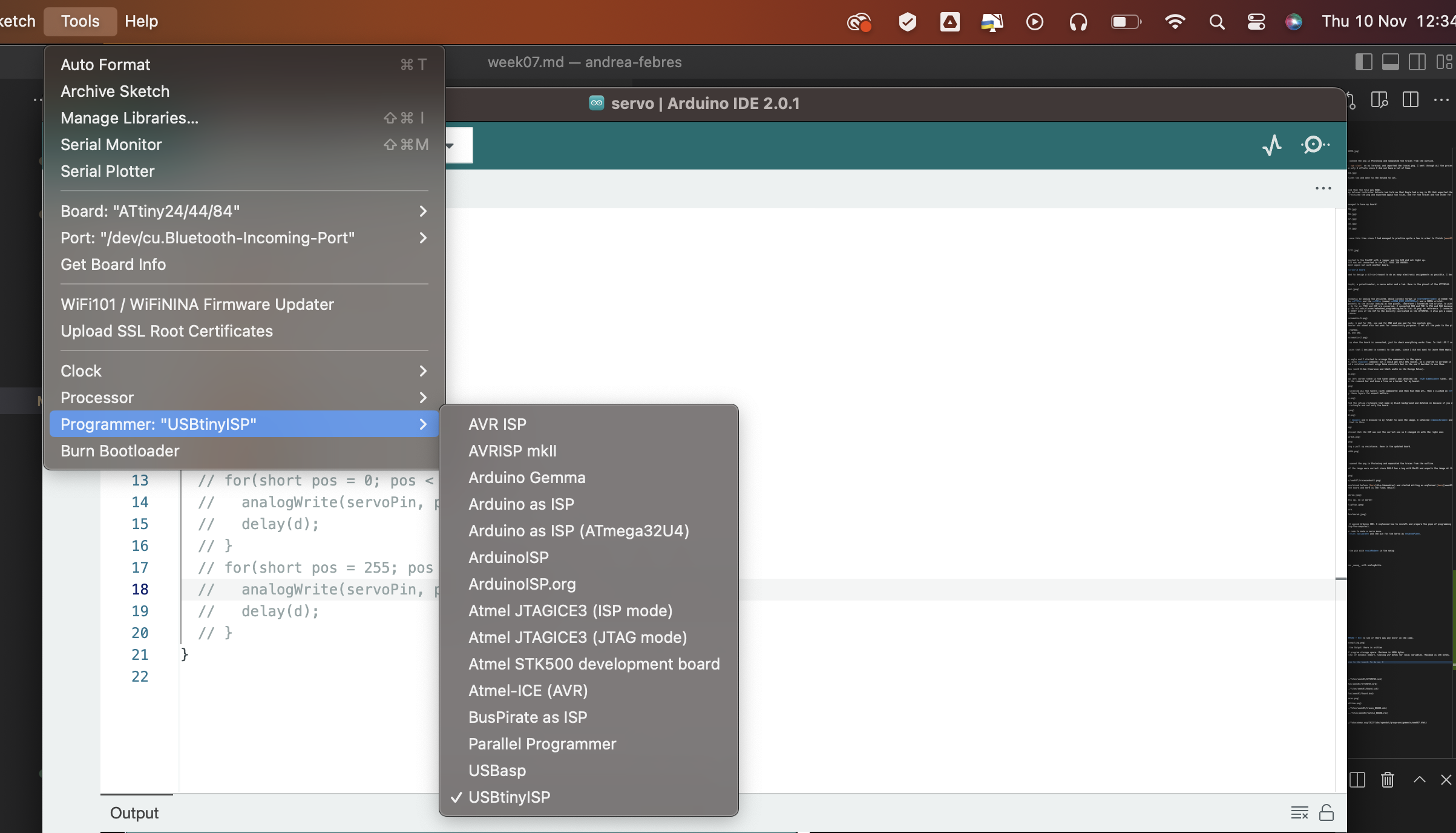
Once I did this, I uploaded the program using a programmer. This is important because if you upload directly it won’t work. To upload using a programmer you can both do Sketch > Upload using a Programmer or do Command + SHIFT + U.
Done this, the servo started to move as you can see in the following video. Here is the hero video that shows that when I rotate the potentiometer, the servo rotates accordingly.
🍓 Hero video
However, I decided to change just a little bit the code and make the servo move backwards when I move the potentiometer.
int servoPin = 8;
int potPin = 7;
int val;

void setup() {
  pinMode(servoPin, OUTPUT);
  pinMode(potPin, INPUT);
}

void loop() {
  val = analogRead(potPin);
  val = map(val, 0, 1023, 0, 180);
  analogWrite(servoPin, -val);
  delay(15);
}
