8. Computer controlled machining
- Make (design+mill+assemble) something big
👩🏽🎤 Design
For this week assignment I started designing on paper. I have a little terrace at home and I do not have a place where to put my beloved plants. Therefore, I wanted to make a shelf for my plants.
The key points for my design were:
make something big; a fast design in terms of 3d modeling; that had less scraps as possible in terms of material use only wood, also in the assembly
🧻 On paper
I made a sketch on paper and decided three components that would compose my shelf: 1. the load-bearing components (4) 2. the shelves (3) 3. the support for the shelves (6)
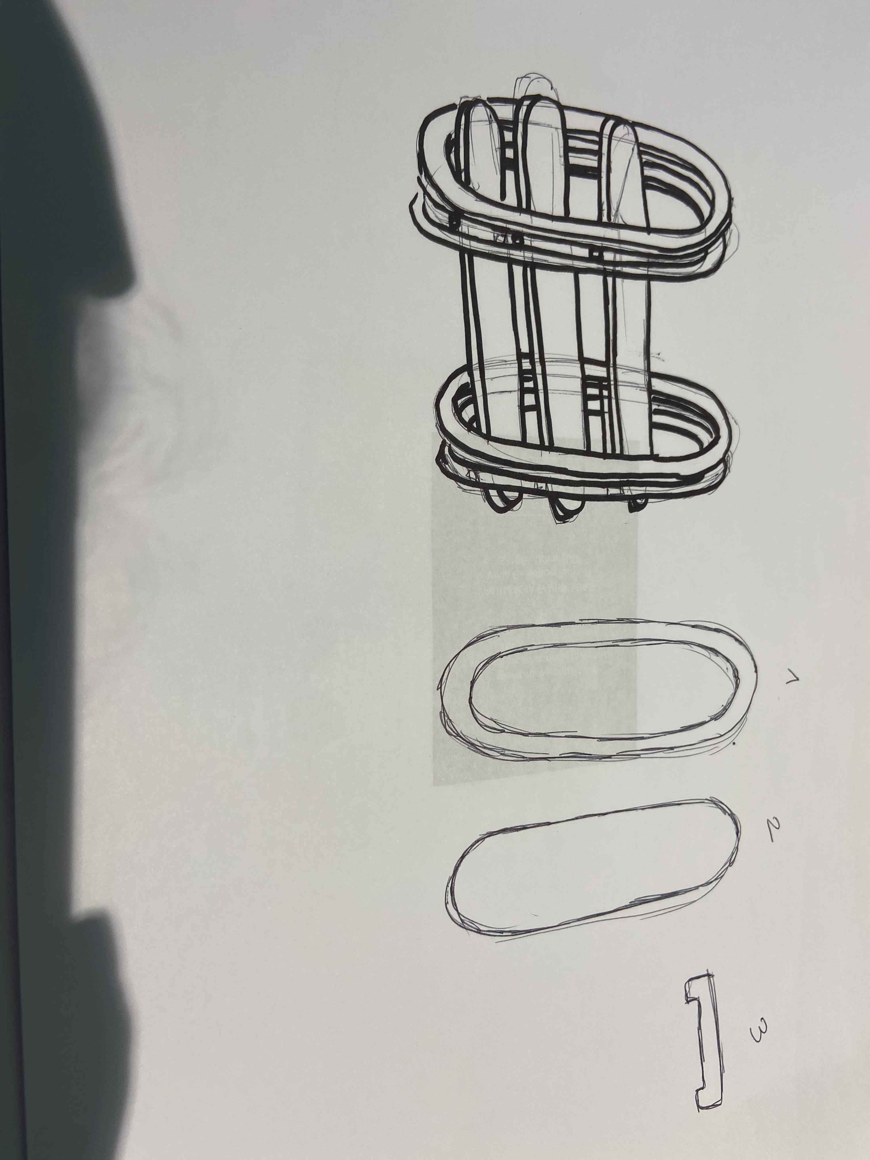
With this design, I could make one countour cut for the external part of the load-bearing components, and the internal cut would mill also the three shelves.
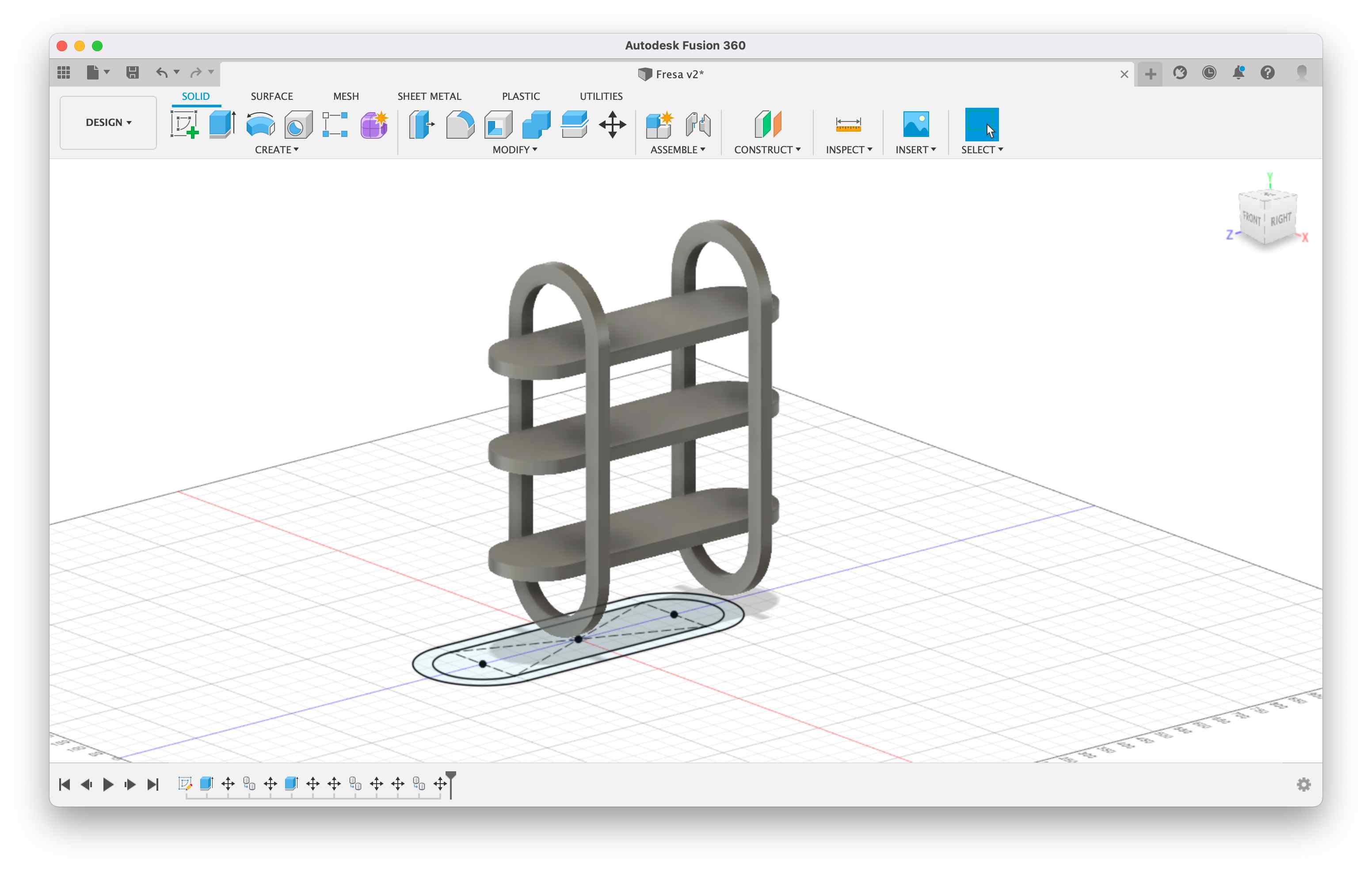
👩🏽💻 3dModeling
For the design, I switched to Fusion360 and created one sketch for the load-bearing components and for the shelves. I extruded the sketch with a height of 18 mm because the plywood stock I would use had that thickness. However, I made that dimension a parameter in order to be able to change it in case something would change. I extruded the shelves too and then duplicated my components in order to have 4 vertical and 3 horizontal shelves and I assembled the pieces.
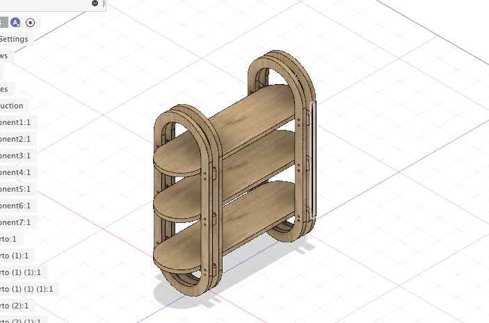
I then designed the supports for the shelves and made the holes for the wood dowels which I chose to be 8 mm diameter. I opted out for a dowel approach instead of a press-fit one because I was using FDM and it tends to deform. This shelf was going to go outside so I feared that with humidity it could deform a lot and therefore I decided to be more cautios and use dowels.
This is the final look of my design.
I then switched to the manufacturing section in Fusion360 in orded to do the CAM part.
💃🏽 Milling
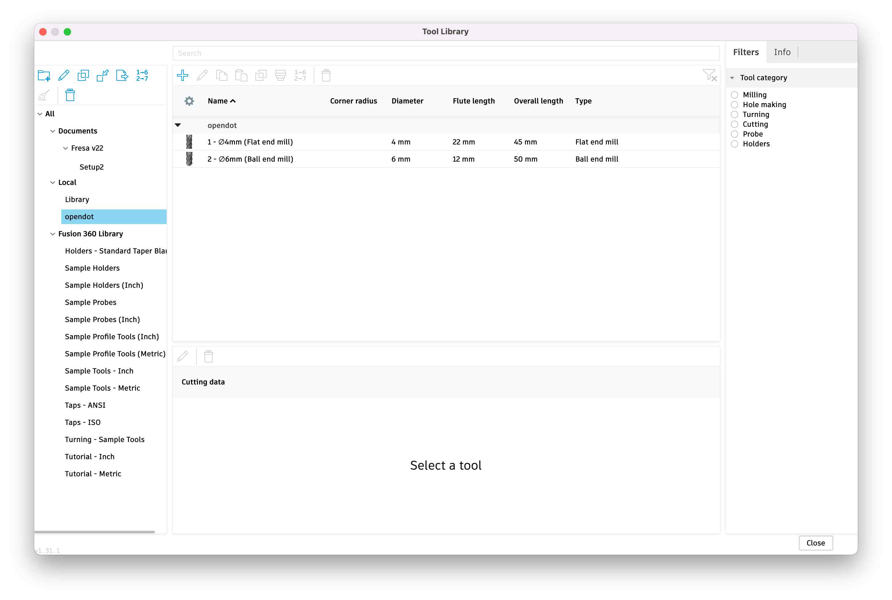
First of all, I added in the Tool Library the two mills I decided to use. I chose a 4mm Flat end mill for the countour and for the drilling part while I decided to use a 6mm Ball end mill for the engraving since I wanted a circular engrave.
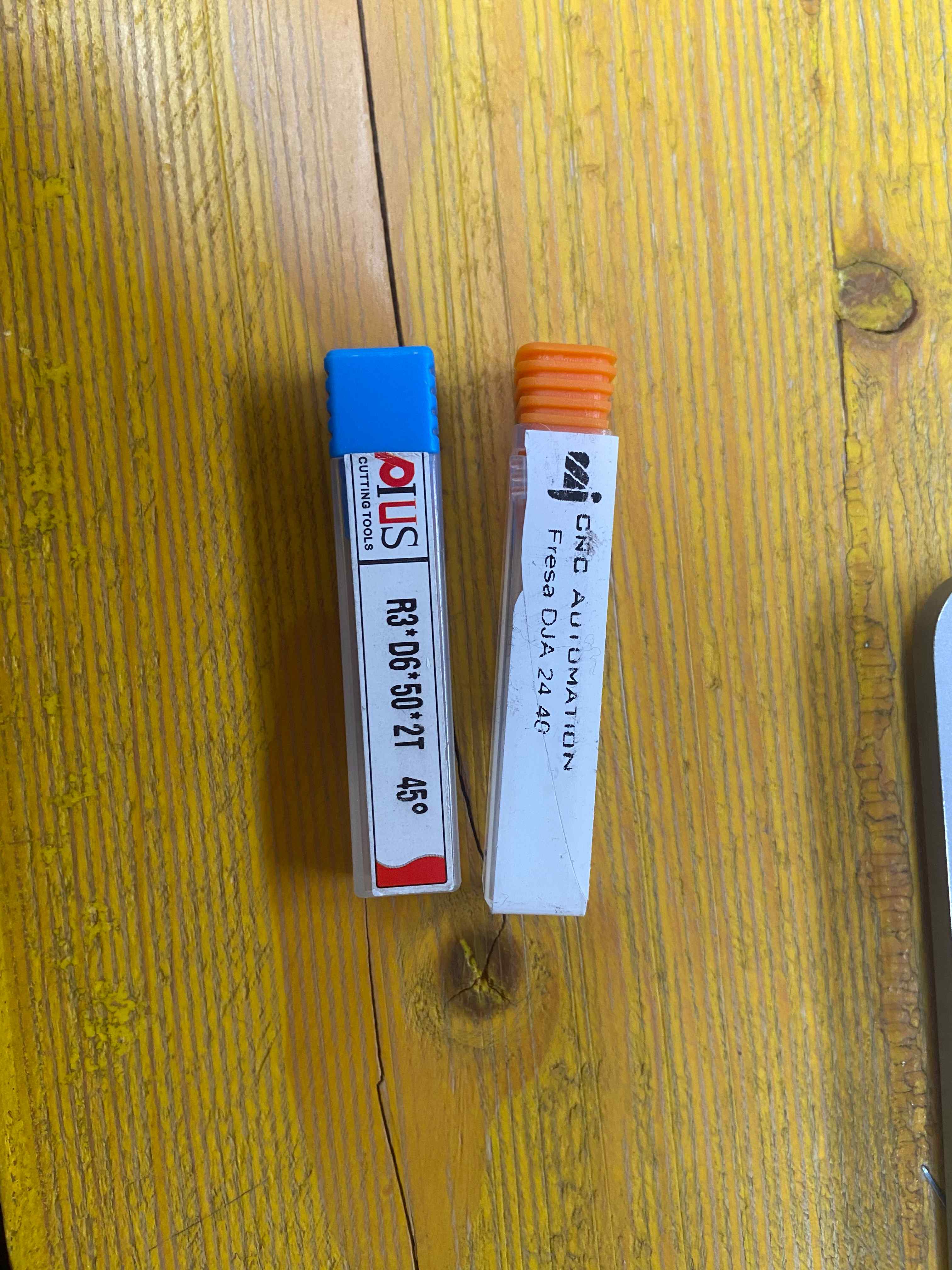
I added the mills by measuring:
diameter (the diameter of the cutting part of the mill) shaft diameter (the diameter of the part that goes inside the spindle) overall length (the length of all the mill) length below holder (the length of the mill from the part that goes inside the spindle to the end of the mill) shoulder length (the lenght of the grooves of the mill) flute length (the length of the cutting part of the flute)
I inserted also the Cutting data. In order to set them, I had to consider that there are certain parameters to consider before setting any cutting file in order to achieve the required finish and accuracy. *Chipload can be defined as the size or thickness of the chip that is removed with each flute per revolution. When material is machined the cutter must revolve at a specific RPM and feed at a specific feedrate to achieve the proper Chipload. There are also several factors to be considered when choosing the proper RPM and feed rate.
The chip load is a measurement of the thickness of material removed by each cutting edge during a cut. This is a valuable piece of information that can then be used to calculate new set ups. Calculation are as follows: Chip Load = Feed Rate (inches per minute) / (RPM x number of flutes). Example: Chip Load = 500 inches per minutes / (15,000 RPM x 2 flutes) Chip Load = .017″.
Chip loads are based on material thickness of average size for cutting edge length of tool. These recommendations do not apply to thicker material or CNC cutting tools with long cutting edge lengths. These chiploads are only a recommended starting point and may not accommodate all circumstances. Therefore, tooling damage may still occur and use of this chart does not warranty against tool breakage.
I used the tables found in cutter-shop to set the parameters. I put them also here.
| Tool Diameter | Hard Wood | Softwood & Plywood | MDF/Particle Board | High Pressure Laminate | Phenolic |
|---|---|---|---|---|---|
| 1/8” | .003” – .005” | .004” – .006” | .004” – .007” | .003” – .005” | n/a |
| 1/4” | .009” – .011” | .011” – .013” | .013” – .016” | .009” – .012” | .004” – .006” |
| 3/8” | .015” – .018” | .017” – .020” | .020” – .023” | .015” – .018” | .006” – .008” |
| 1/2” & up | .019” – .021” | .021” – .023” | .025” – .027” | .023” – .025” | .010” – .012” |
Since I am using MDF panel and a tool with diameter 4mm and 6 mm (in between 1/8” and 1/4”) and I was cutting MDF, I had to consider a chipload between .007” and .013” more or less.
Considering also that for optimal jobs a special formula can be used to calculate the most suitable feed rate for that job. The formula is:
Feed Rate = RPM * number of tip grooves * chipload
Therefore, in particular I set:
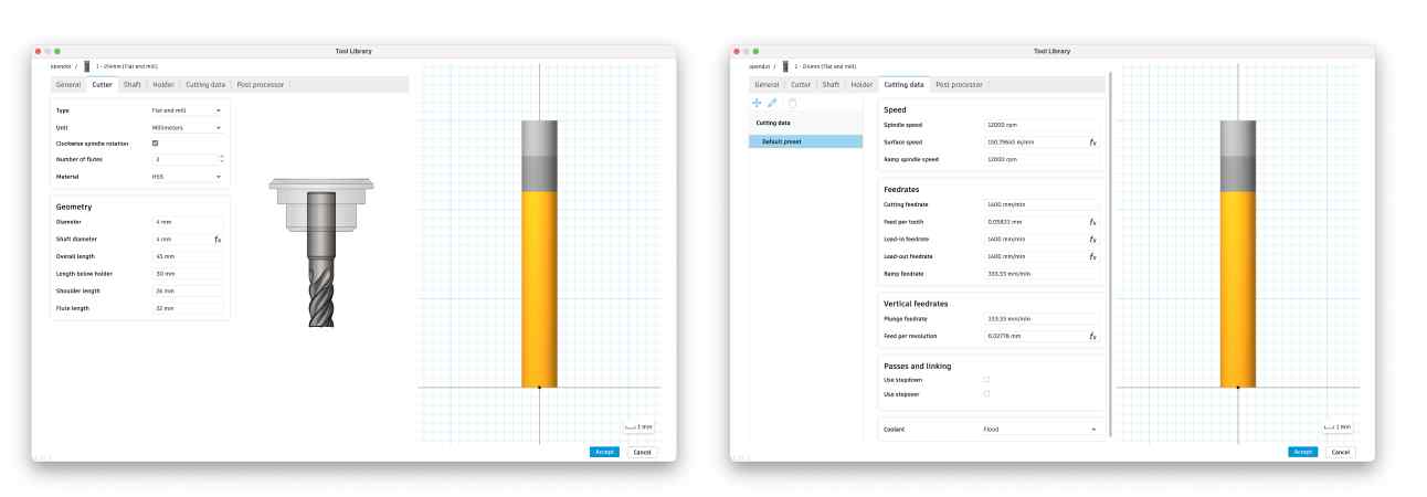
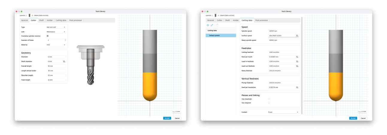
- spindle speed at 12000 rpm because I was going to cut MDF
- ramp spindle speed equal to the spindle speed in order to not “lose time”
Applying the formula I ended up with my feedrates:
- For the Flat end mill Cutting feedrate 1400 mm/min because it had to do the drilling and the contour part with that mill
- Cutting feedrate 1100 mm/min because it was for the engrave.
🕴🏽 CAM
After setting the tools, I started creating a Manufacturing model in the Setup section. IMPORTANT: to do so, you have to convert all your bodies in the DESIGN section in COMPONENTS.
After doing so, I setup the manufacturing model as follows: I selected the Millin operation type, I set the X an Y axis in the WCS section in order to have them aligned with the ones of the ShopBot, flipping the X axis. I also set the origin on top of the stock.
I selected the models, leaving out the shelves because that pieces were already considered in the inside of the load-bearing components. I set the size of my stock, with was 1900mm x 1500mm and I set the Stock Side offset to be 20mm. I set to 0 the Stock top offset, the stock bottom offset and the round up to nearest.
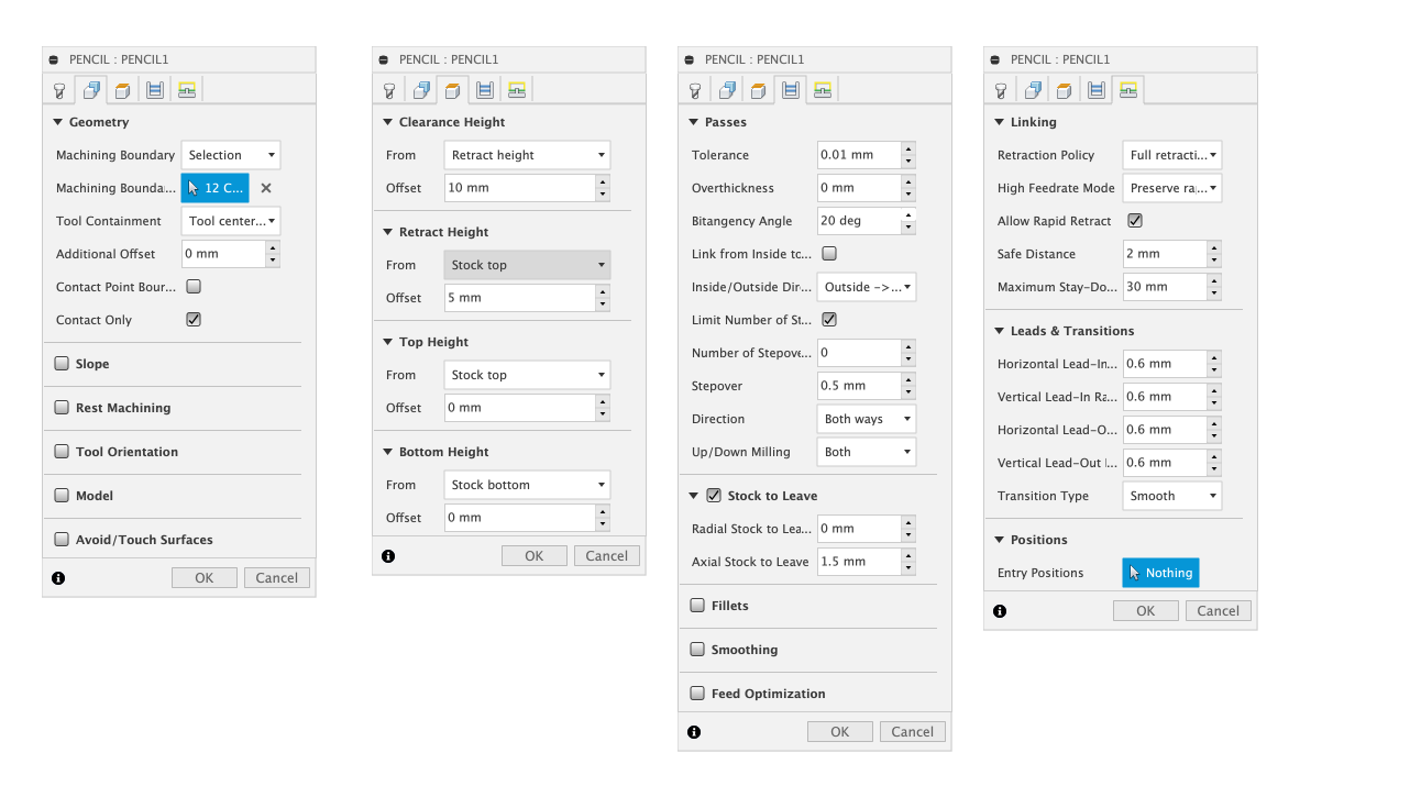
✏️ Pencil
First of all, I set the Pencil (which is under 3D processes) to do the engraving. I selected the 6mm Ball end mill and all the boundaries of my engraving cut. Since I wanted a 3mm deep engrave, I did a first Pencil process with Stock to leave ( in the Passes section) with 1.5mm of Axial stock to leave and then duplicated the process leaving 0mm of stock.
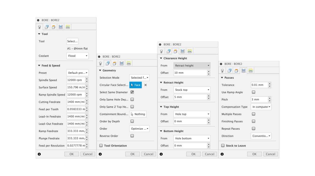
💍 BORE
I then continued the CAM by doing the holes for the dowels. I did this by using the bore command, which creates a spiraling helical cut. I did not use the drill because my mill was 4mm diameter and the hole were 8mm so I thought that the bore would work best.
I selected the tool (4mm flat end) and in the geometry section I first of all clicked on Select same diameter and then selected the circular face. In this way, Fusion selected automatically all my holes with the same dimension. I set the Pitch to be 3mm and everything else as you can see in these screenshots.
🪖 CNT
I used the 2D contour to do the cutted parts and first of all I selected the tool, my flat end 4mm mill. I selected only the external cuts and the support parts because I wanted not to have tabs in these components since I would have been able to fix the wood to the machine after the bore process. In this case in the heights section I set the bottom height to be -0.05mm in order to be sure to have a little margin when cutting.
I duplicated the 2D contour and selected the internal profiles of the shelves and in this case I created triangular tabs.
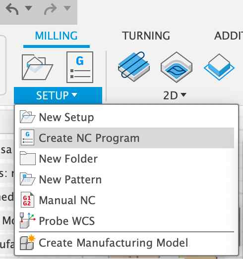
🫥 NC programs
I then reordered everything putting the pencil processes first, then the bore and lastly the contour since I wanted to change the mill once. I then selected my two pencil processes and created a new NC Program. I selected in POST the machine we have in our lab and posted my process. I did the same for the bore and for the contour.
🤠 ShopBot
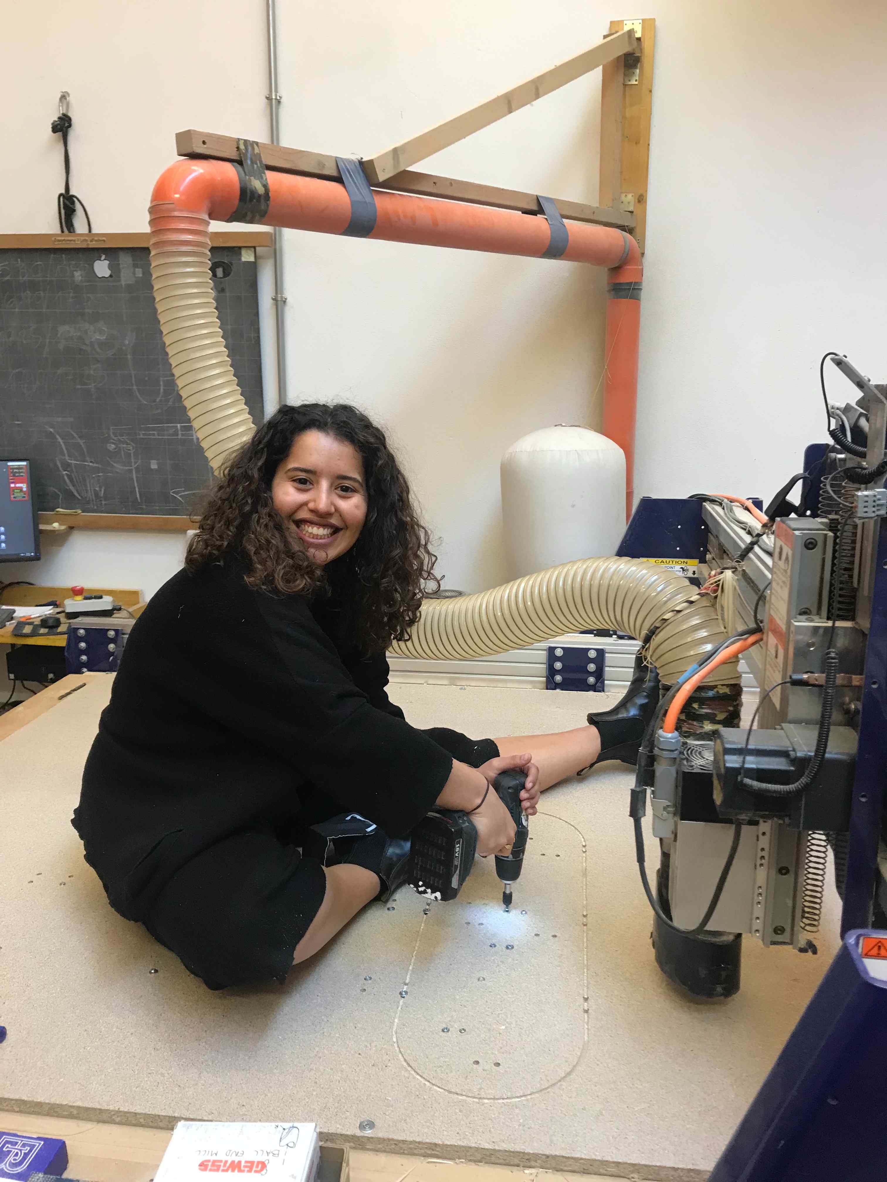
First of all, I had to cut the plywood. I did not do this by myself but Antonio and Alberto helped me and cut the stock in the dimensions I set. Then I put the stock on the machine and fixed it to the cutting board with screws.
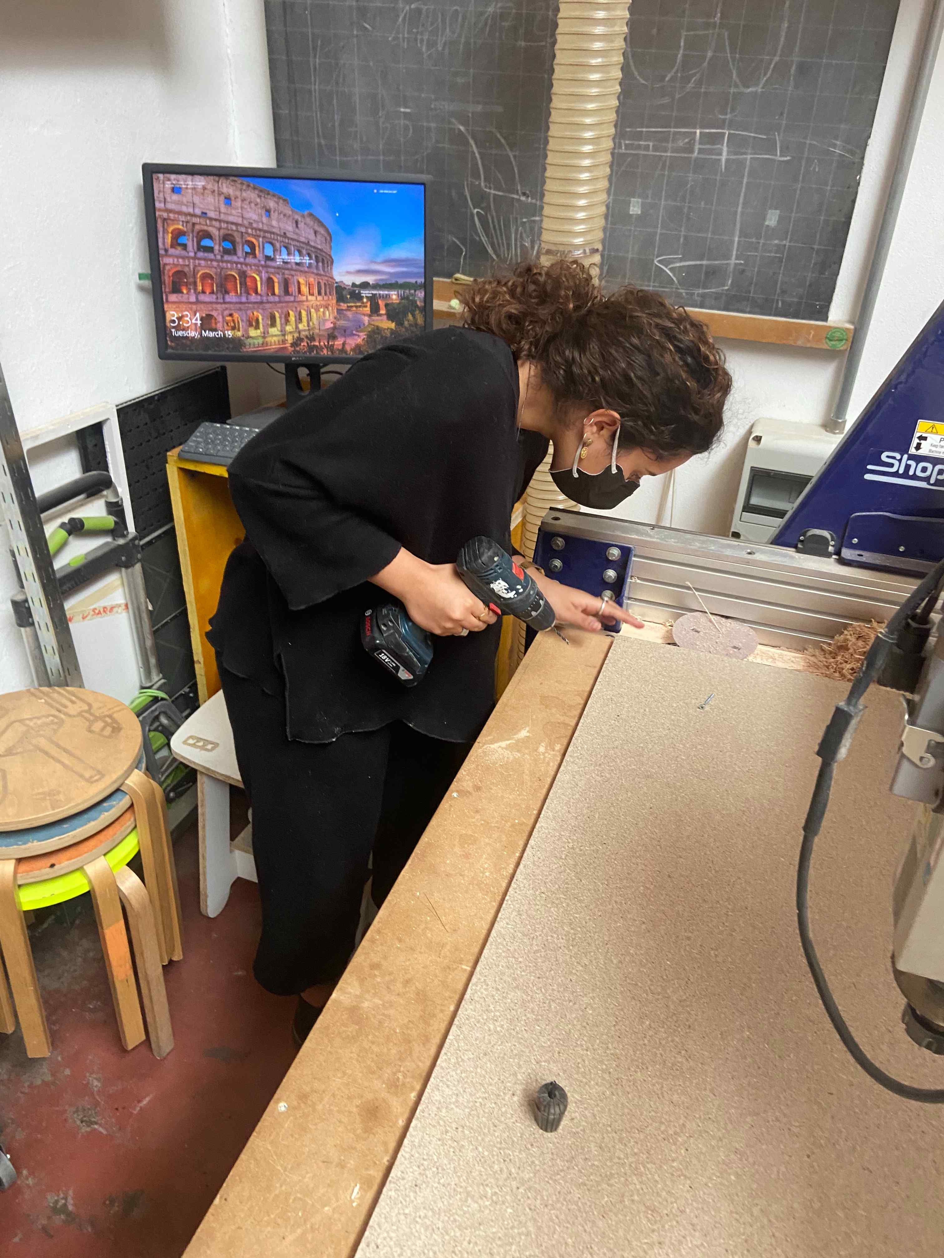
I changed the mill and put the 6mm ball end mill and then calibrated the x, the y and the z origin. I opened the pencil.sbp file and started cutting.
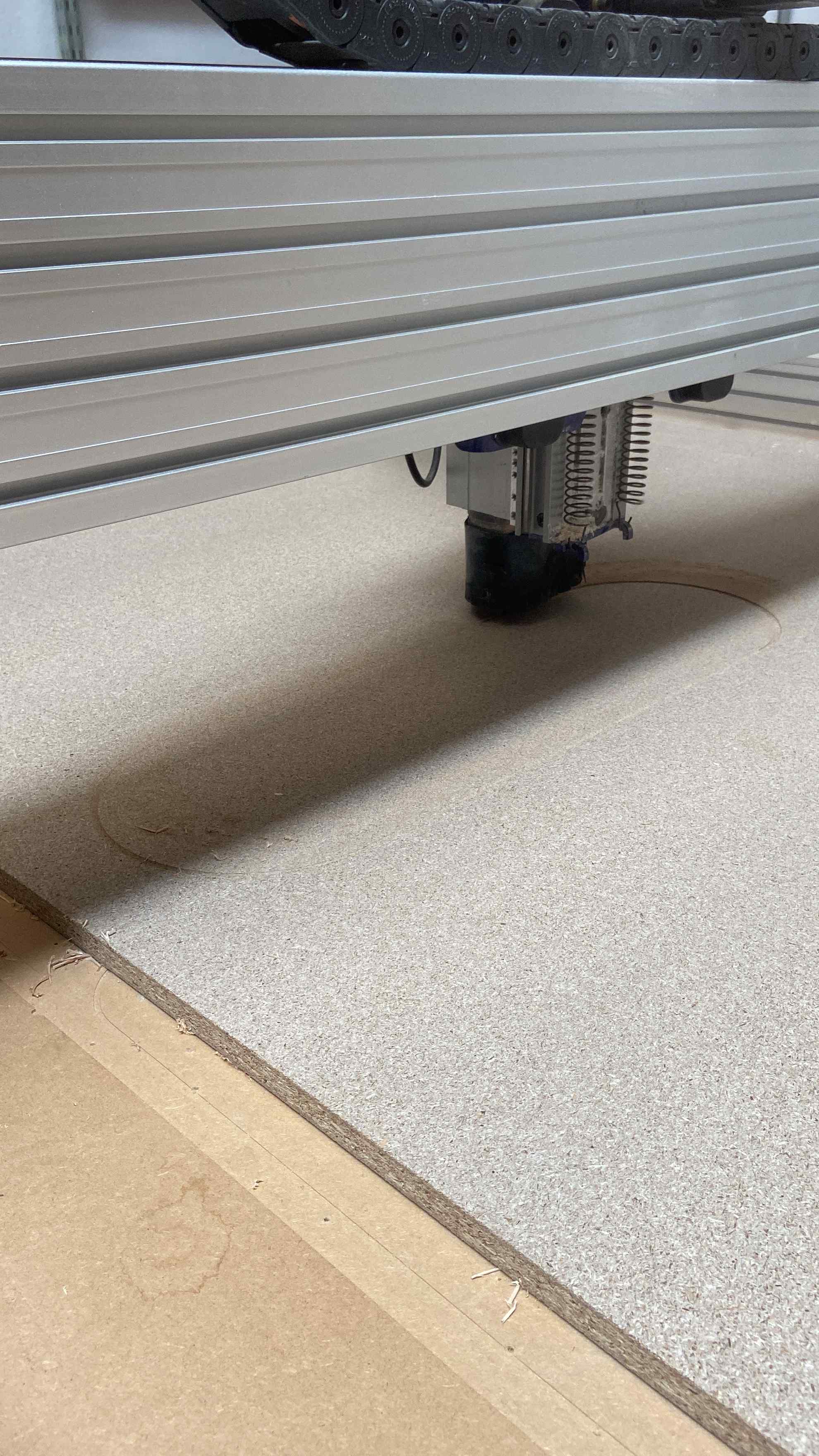
When that process was over, I changed the mill and put the 4mm Flat end mill. I then started the bore process. Once that was over, too, I used screws to fix the plywood to the board. This was really fun.
Once everything was nice and screwed, I procedeed in doing the countour. 36 minutes later, the processes were finished and I unfixed everything and started to detach every piece with the help of a saw.
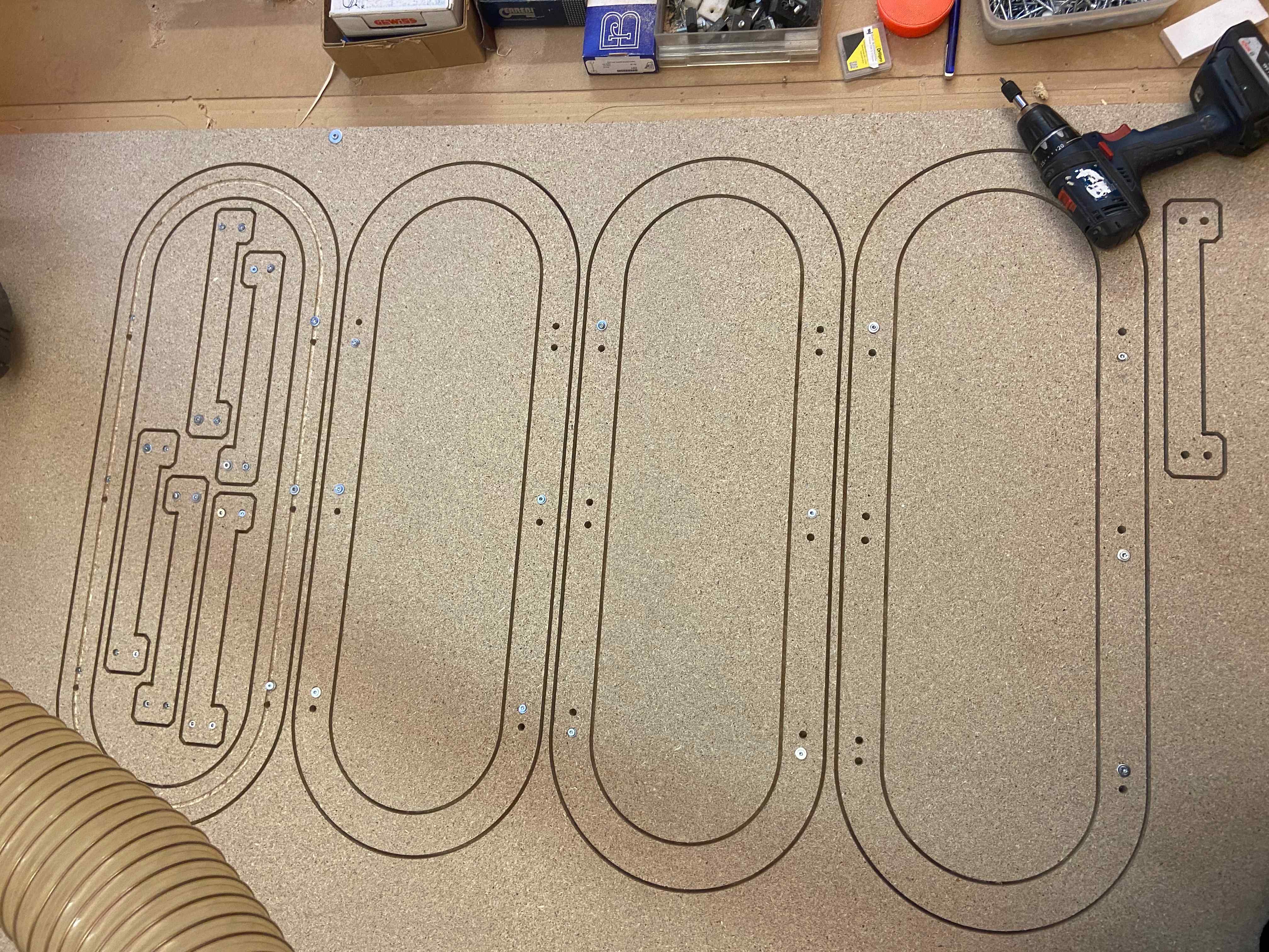
I sanded the pieces and started to assembly.
🔨 Assembly
For the assembly, I took the dowels and started to hammer them into my holes. Everything turned out quite fine even if I need to sand better the final piece.