7. Electronics design
- Redraw one of the echo hello-world boards or something equivalent, add (at least) a button and LED (with current-limiting resistor) or equivalent input and output, check the design rules, make it, test it. Optionally, simulate its operation.
👩🏽🎤 Redrawing and a hello-world board
For this week assignment, since I have no clues on electronics, I decided to start with the basics. I chose to redraw a board with an ATTINY45: this one.
👩🏽🍳 EAGLE
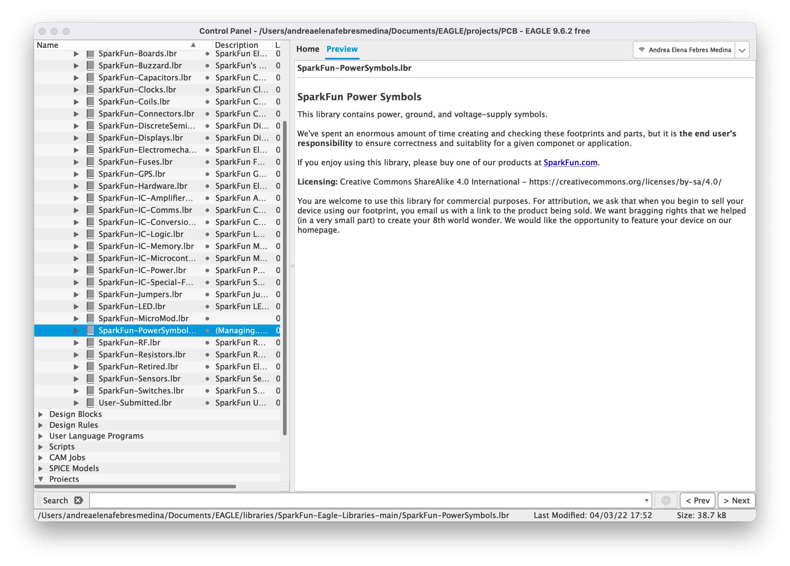
To redesign the board, first of all I installed Eagle and I imported the fab library following the instructions in the README of their github page. I had some troubles in seeing the library in the libraries folder, so I did some trials until I discovered that with the right click I could add the library to the Managed Libraries and I could see it in the correct folder.
I then created a project and inside the project I created a new schematic.
👩🏽🍳 SCHEMATIC
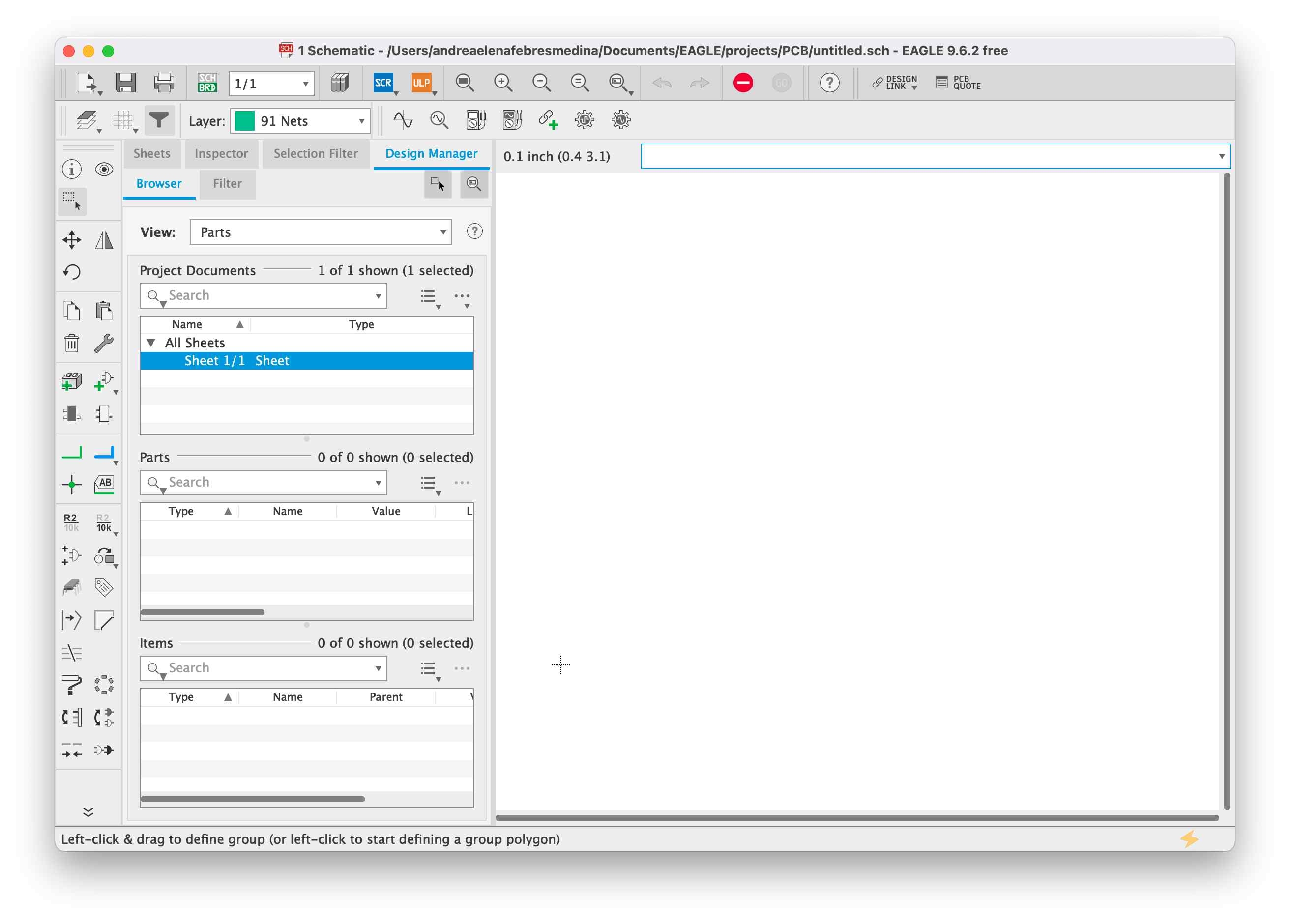
The first thing I needed to understand, was the whole interface of Eagle. I started to add components and faced the problem of the search: I searched for the ISP and at first I could not find the fab library. I understood that I needed to change the filter for the managed libraries and I could see it then. I found the ISP that was named CONN_03X2_AVRISPMD thanks to Aziz Wadi who has a fantastic table with the codes of each component.
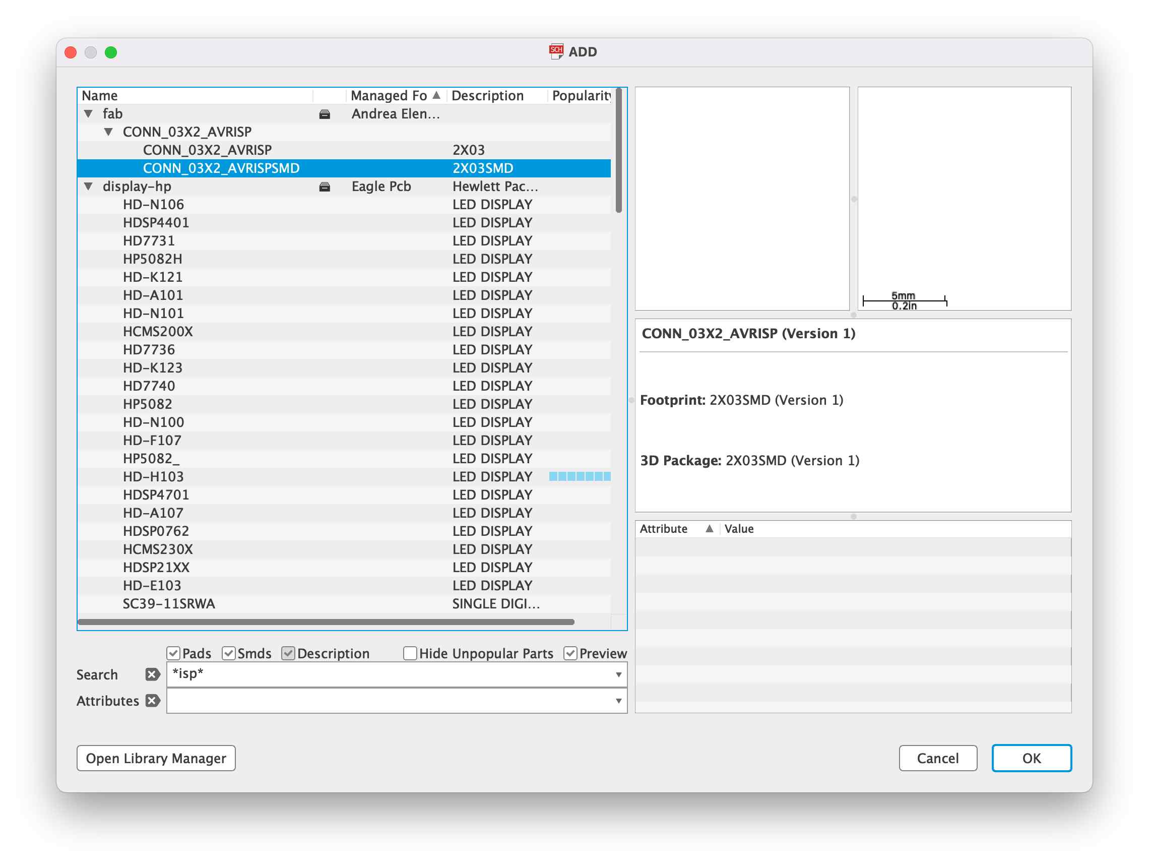
I then proceeded to add all the other components for the basic board (without LEDS and SWITCH).
I used the net command to net all the components following the connections of the board I chose.
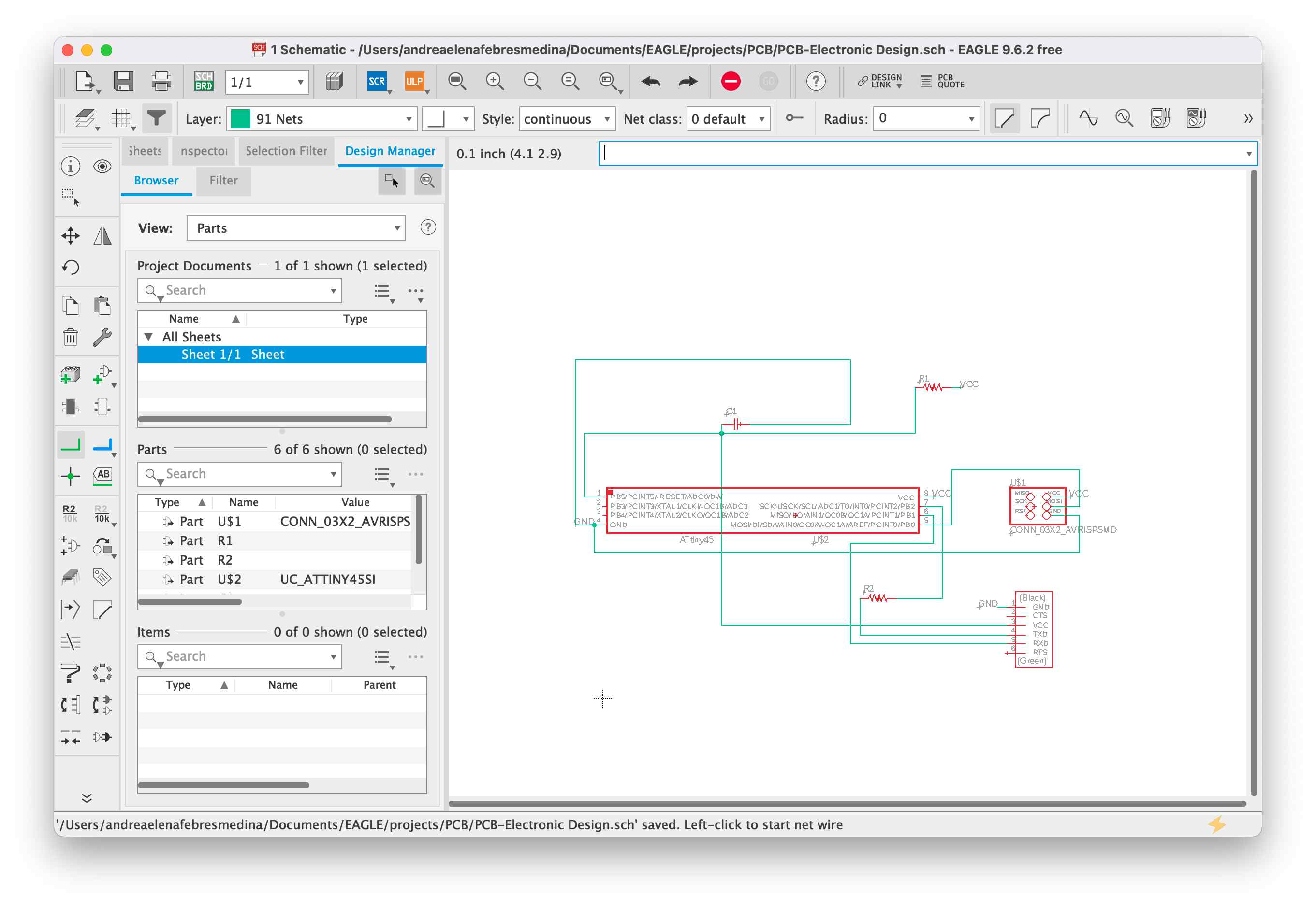
I then switched to a BOARD file.
👩🏽🍳 BOARD
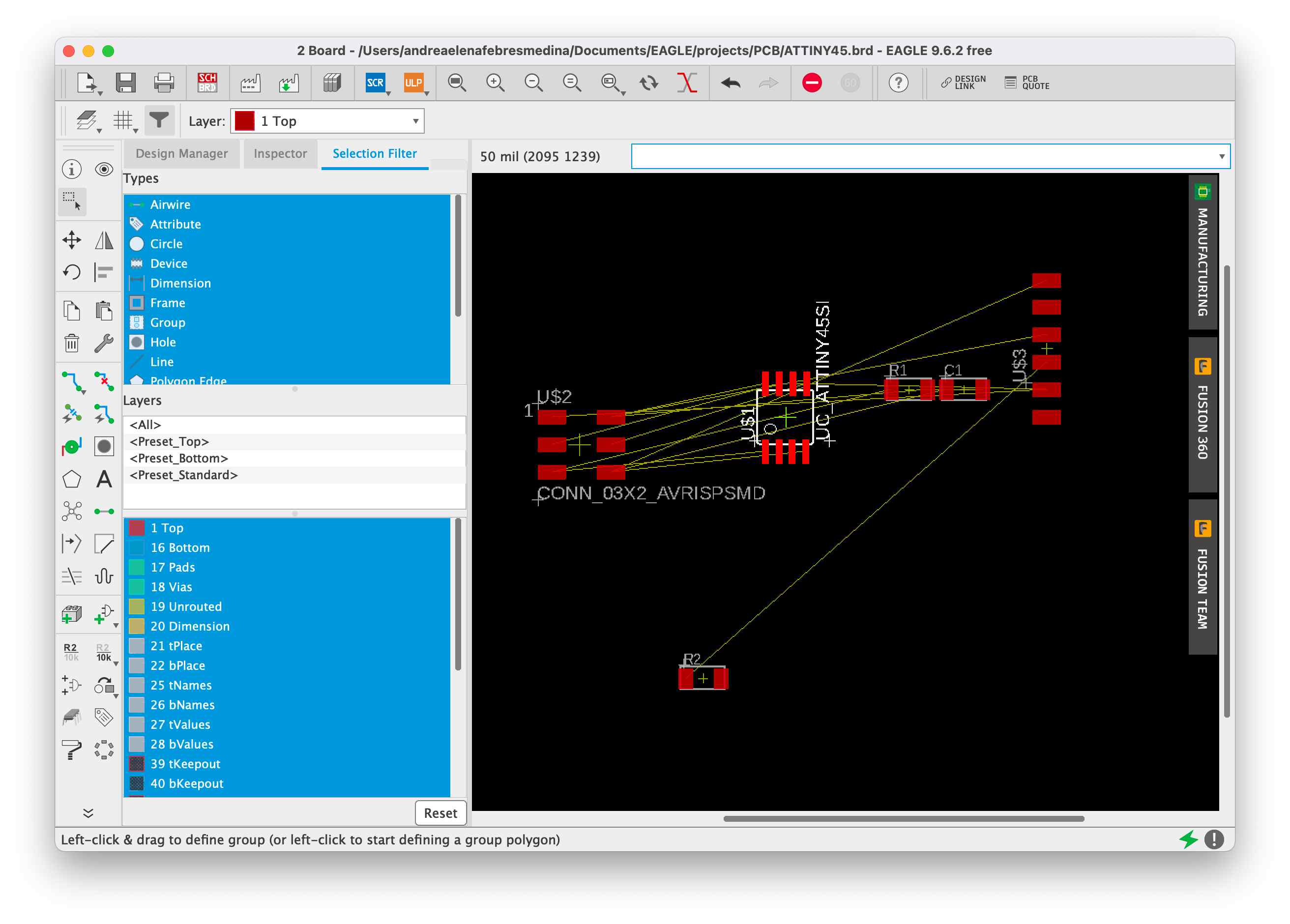
The first thing I did was to set the net classes: Clearance 0.5mm and width 16 mil.
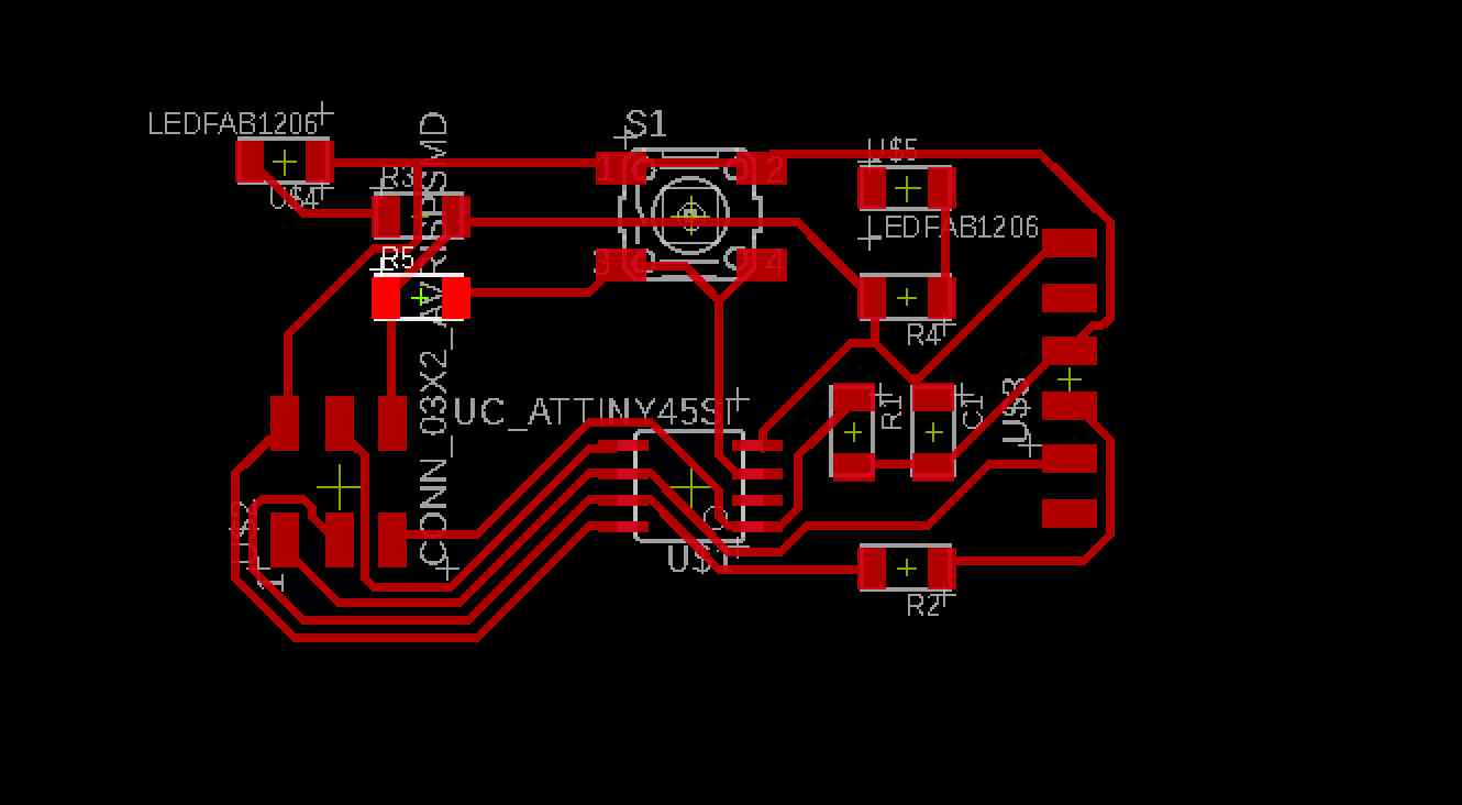
And then I tried to route by myself the components. I rotated the component that had links that were strange and moved the components in order to have a cleaner board.
Needless to say, I tried the autorouter right after.
and I chose the final “look” of my board.
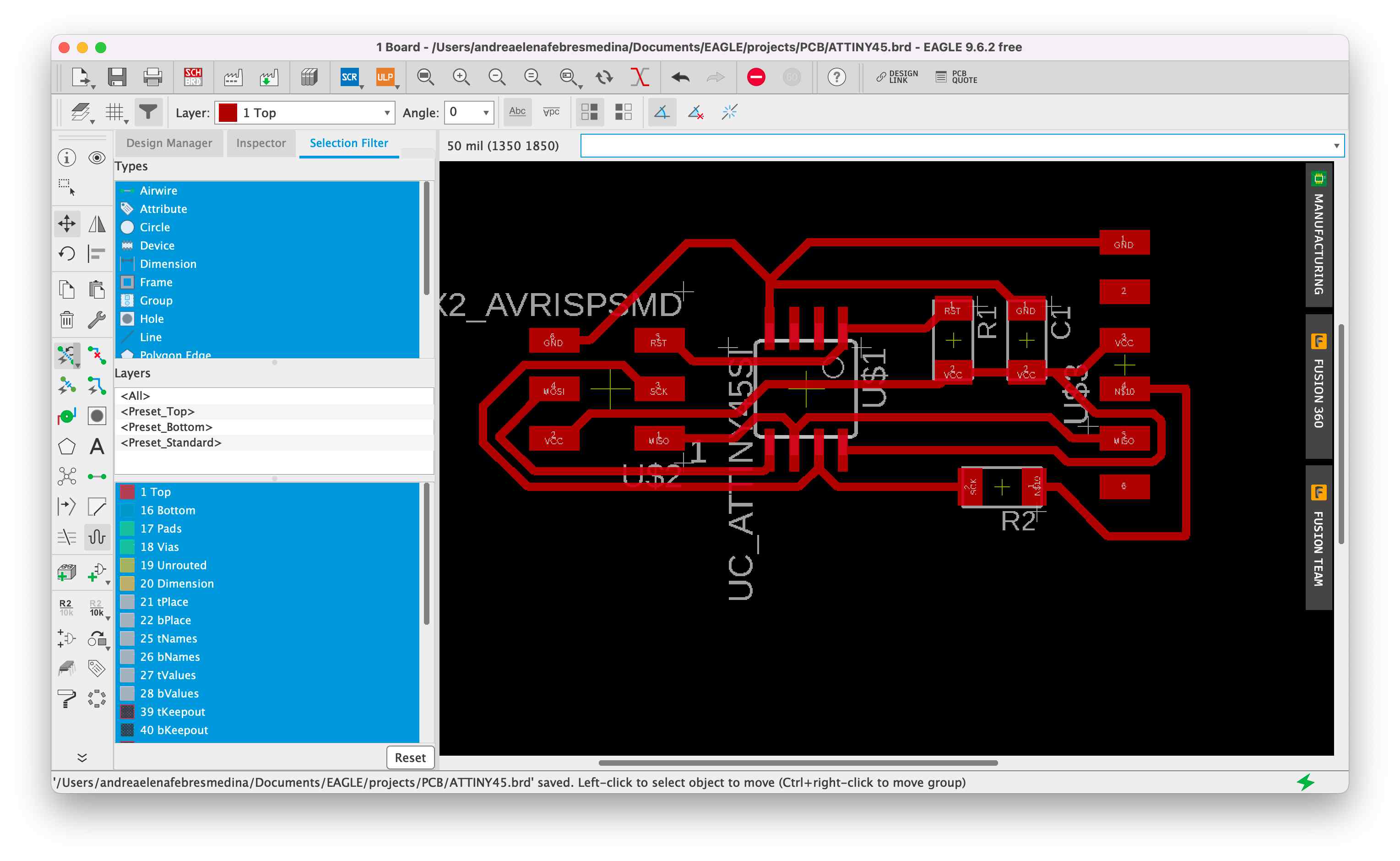
I then proceeded to check with the drc command the Design Rules of my board and since everything was ok, I went on adding two LEDS and a SWITCH.
🌶️ Make it spicy
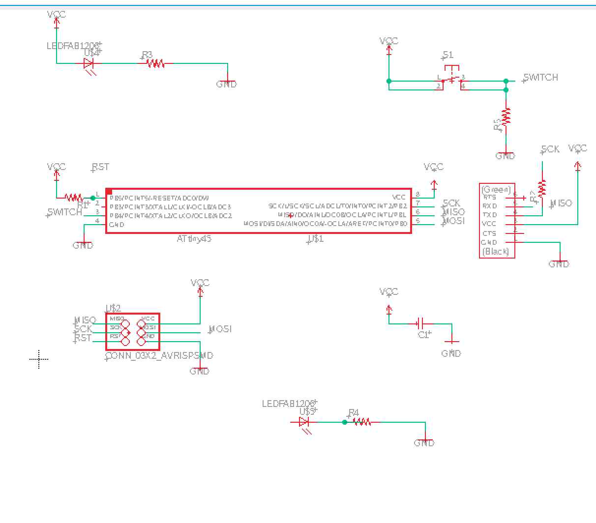
I created another schematic and added the same components as before. I then added two libraries: SparkFun Power Symbols and SparkFun Connectors.
I added the two leds and one switch to my schematic and I added the VCC and the GND components in order to net without having to physically link the components between each other.
I then named the connections that were missing such as MISO, MOSI, SWITCH, RST and SCK until I reached this result.
I switched to the board and seen the output, I started to move the components to have the connected components closer.
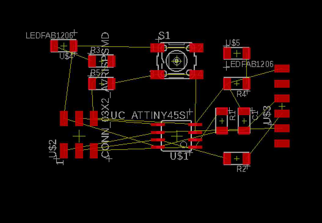
I directly used the AutoRouter and since I was not happy with the result, I rerouted some routes.
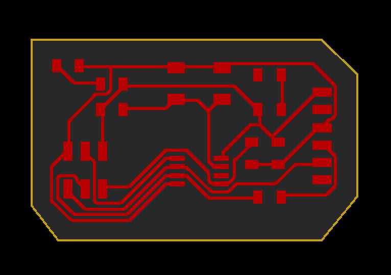
Once I was satisfied, I created with the command line the outline of my board on the level 20 Dimension and proceeded to export the file as an Image.
🫐 FabModules
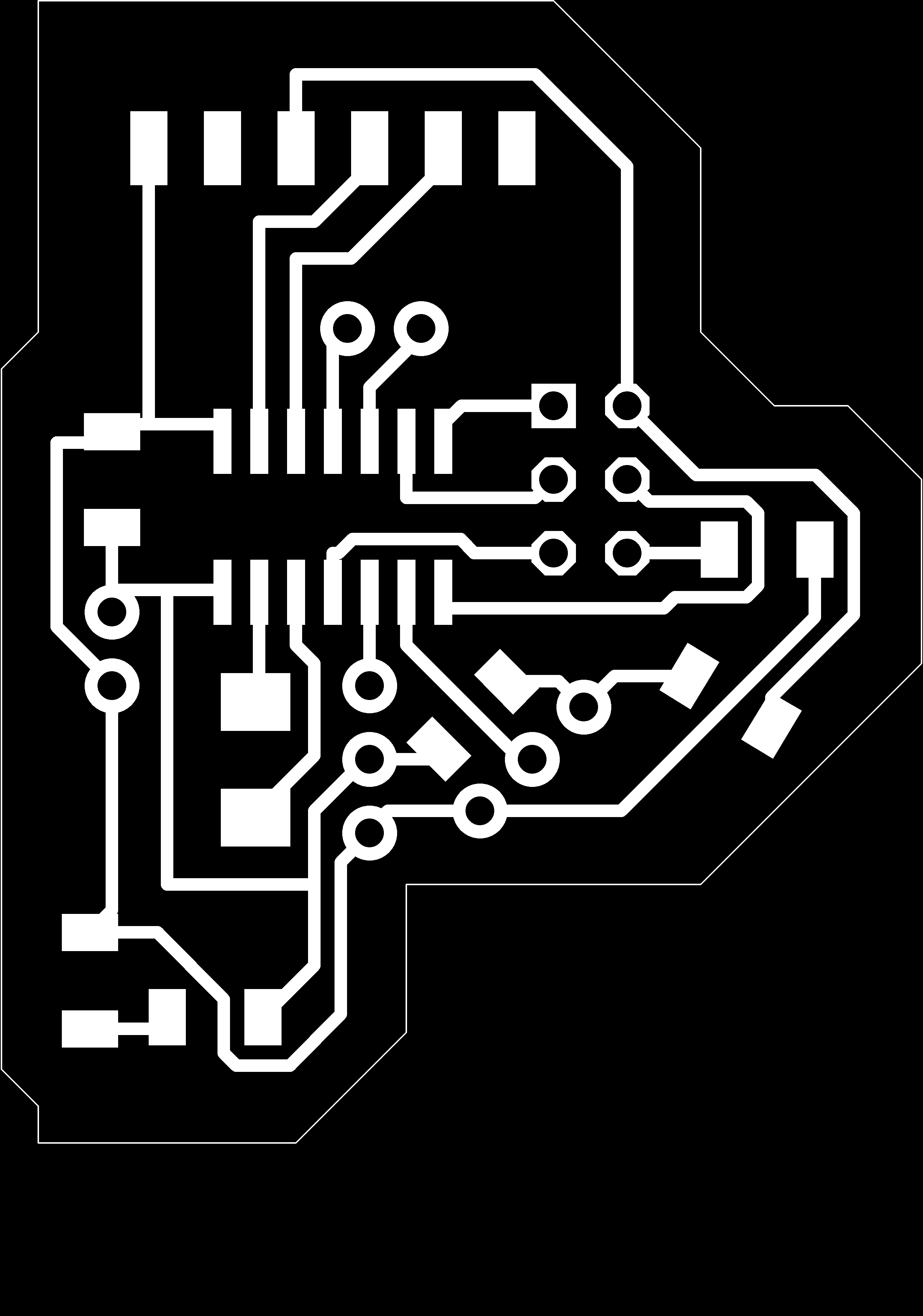
Before going in fab modules, I opened the png in Photoshop and separated the traces from the outline.
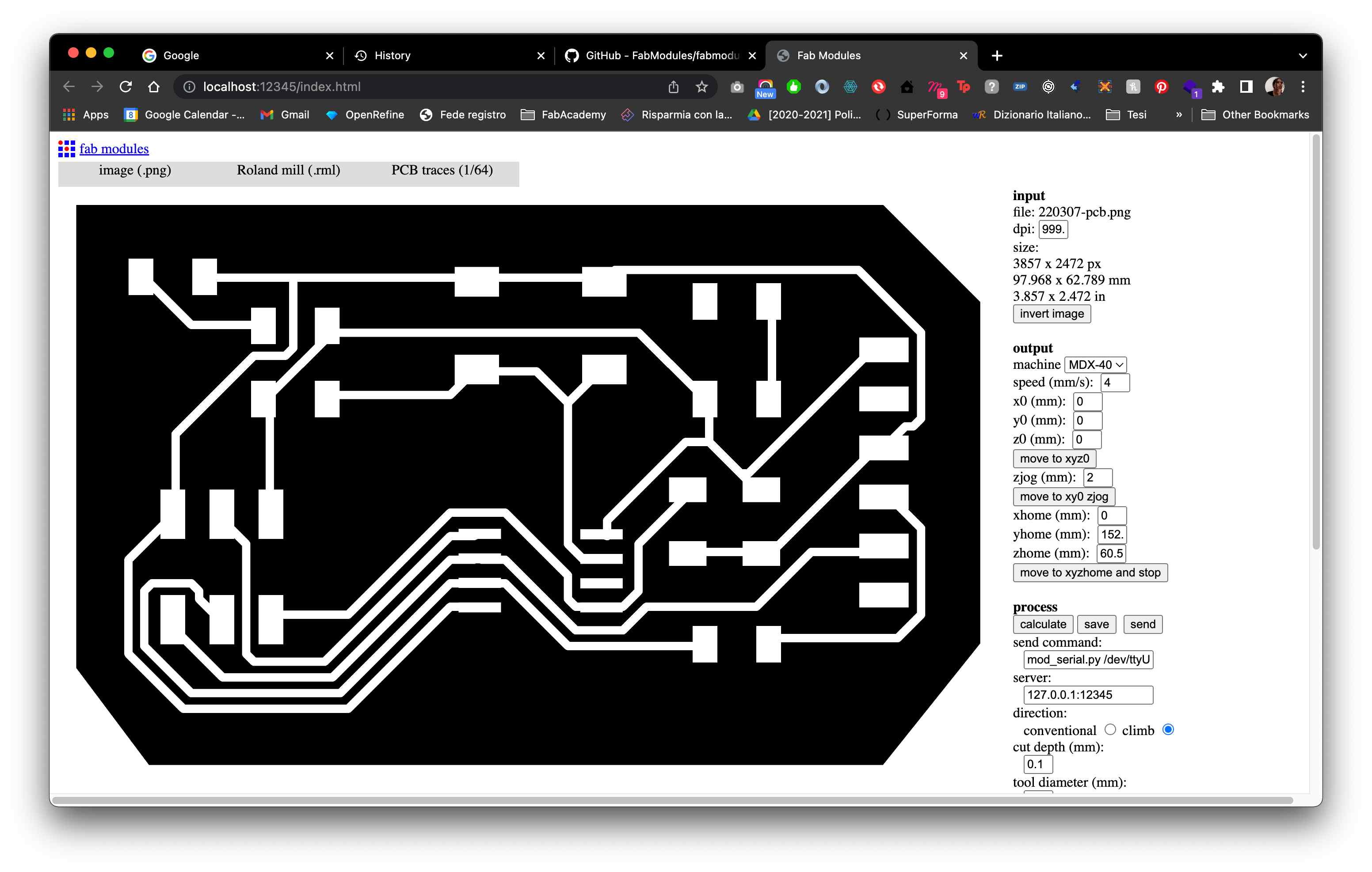
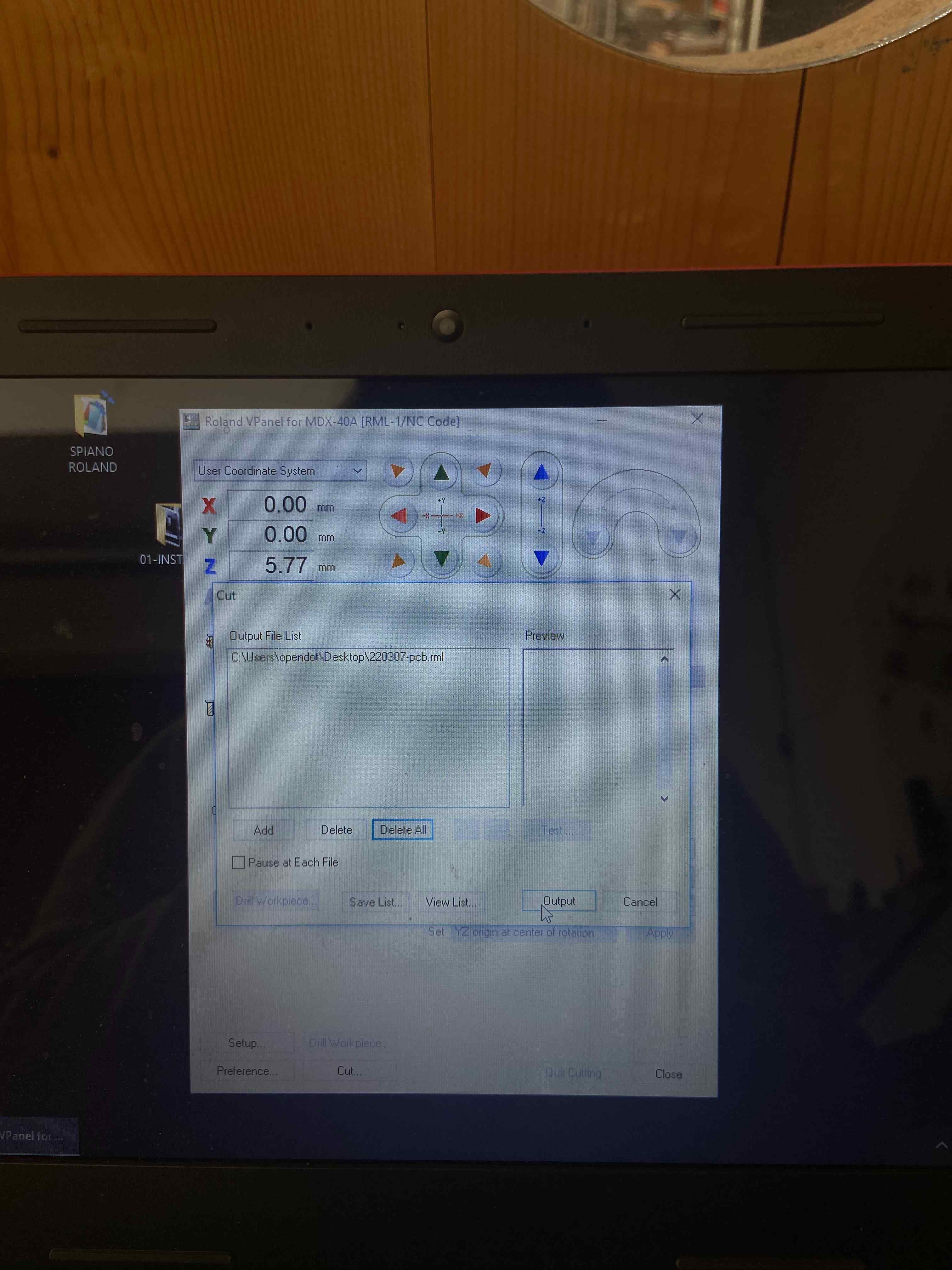
I then started fabmodules with npm start on my Terminal and imported the traces.png. I went through all the process for the Roland MX40 and decided to have only 4 offsets since I did not have a lot of time.
I did the process with the outlines too and went to the Roland to cut.
🐝 Milling
🌚 Size matters
When I started cutting, I noticed that the file was HUGE. That’s when I remembered that my beloved instructor Antonio had told me that Eagle had a bug in OS that exported the files bigger. I went back to my computer and resisized the png and exported again two files, one for the traces and the other for the outline.
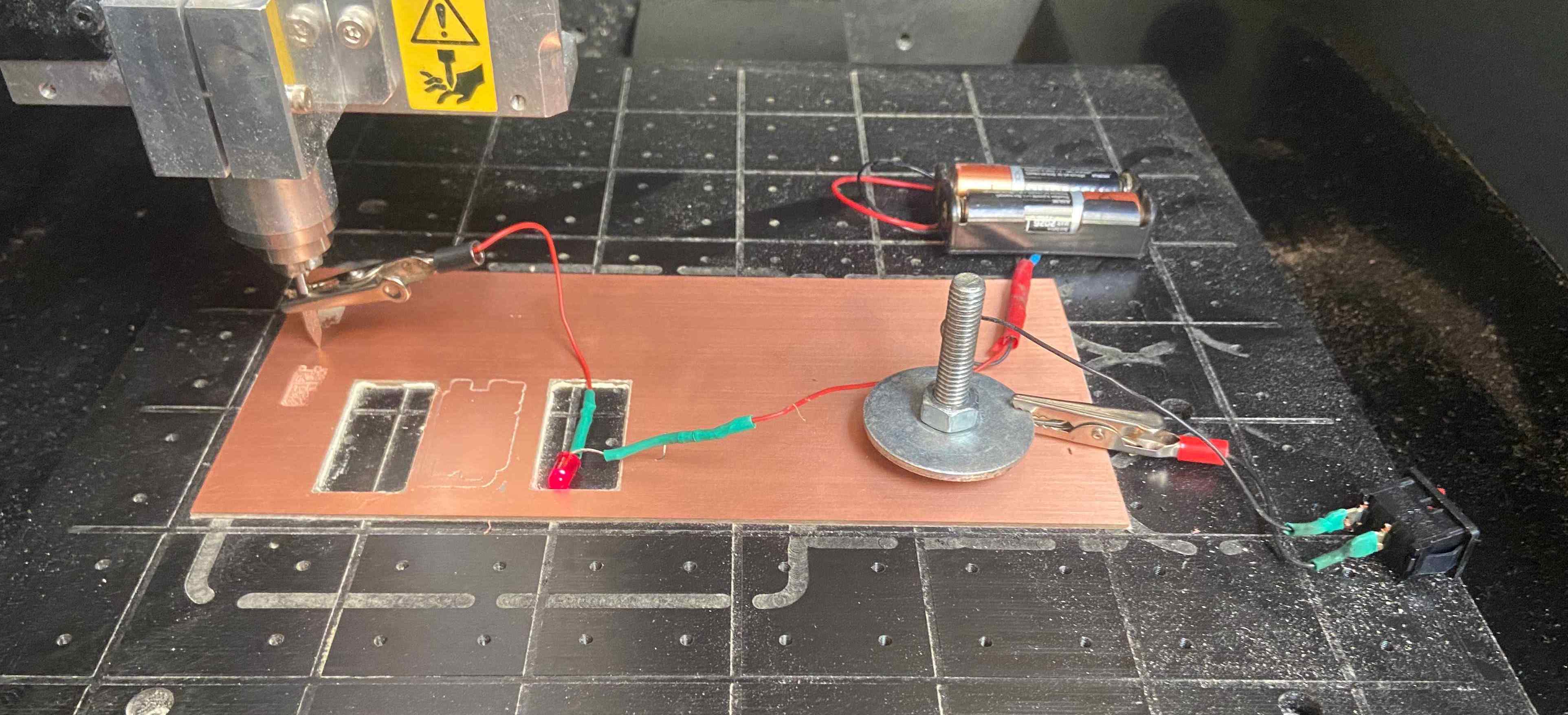
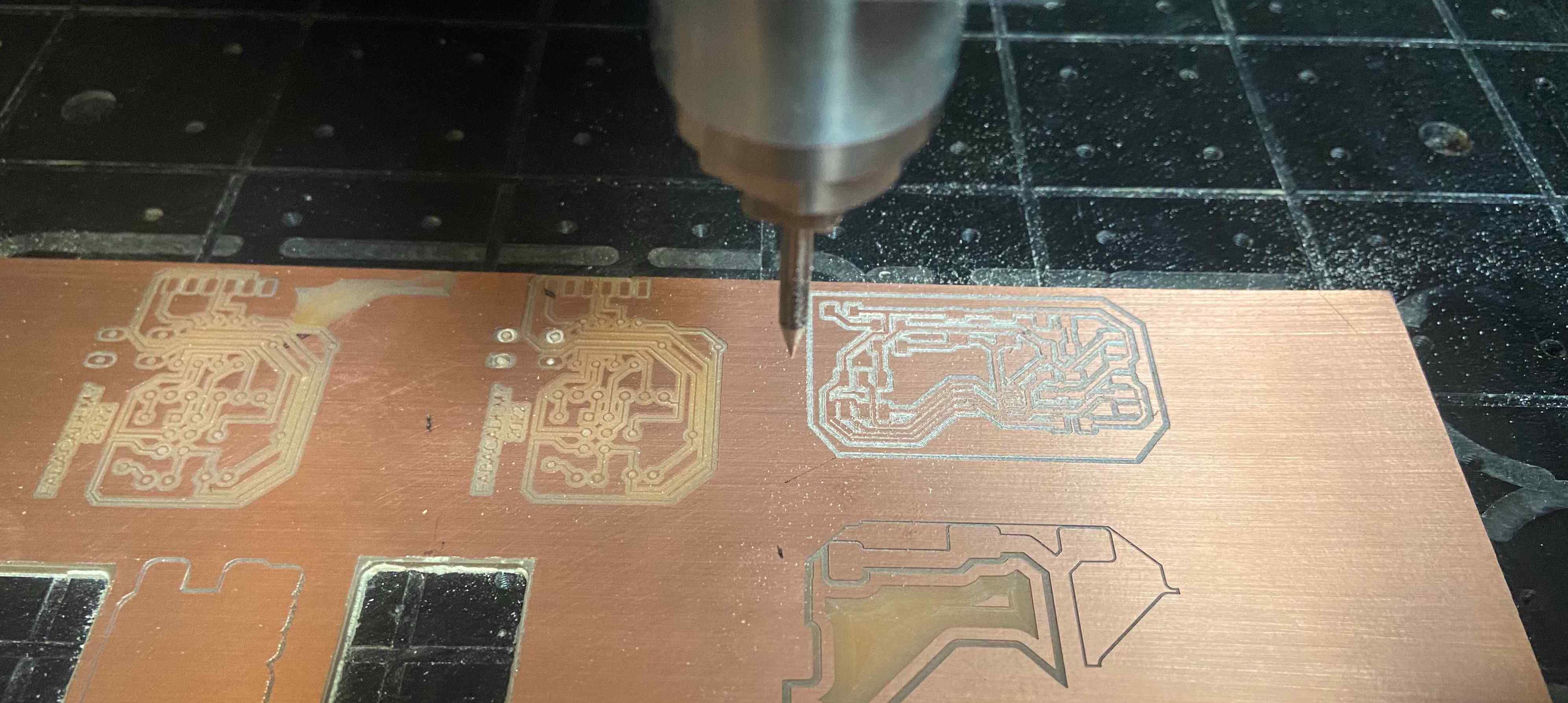
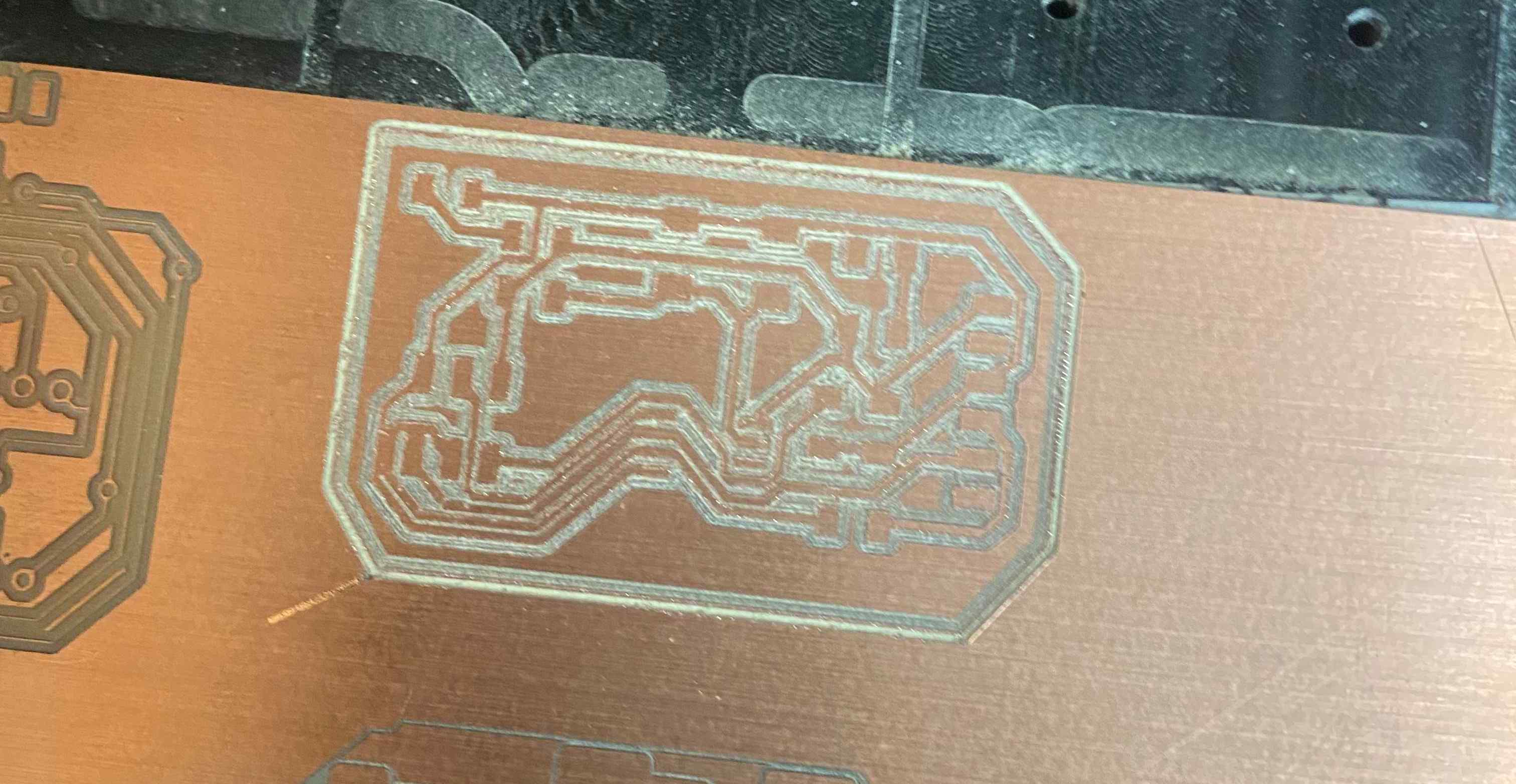
💫 Back on track
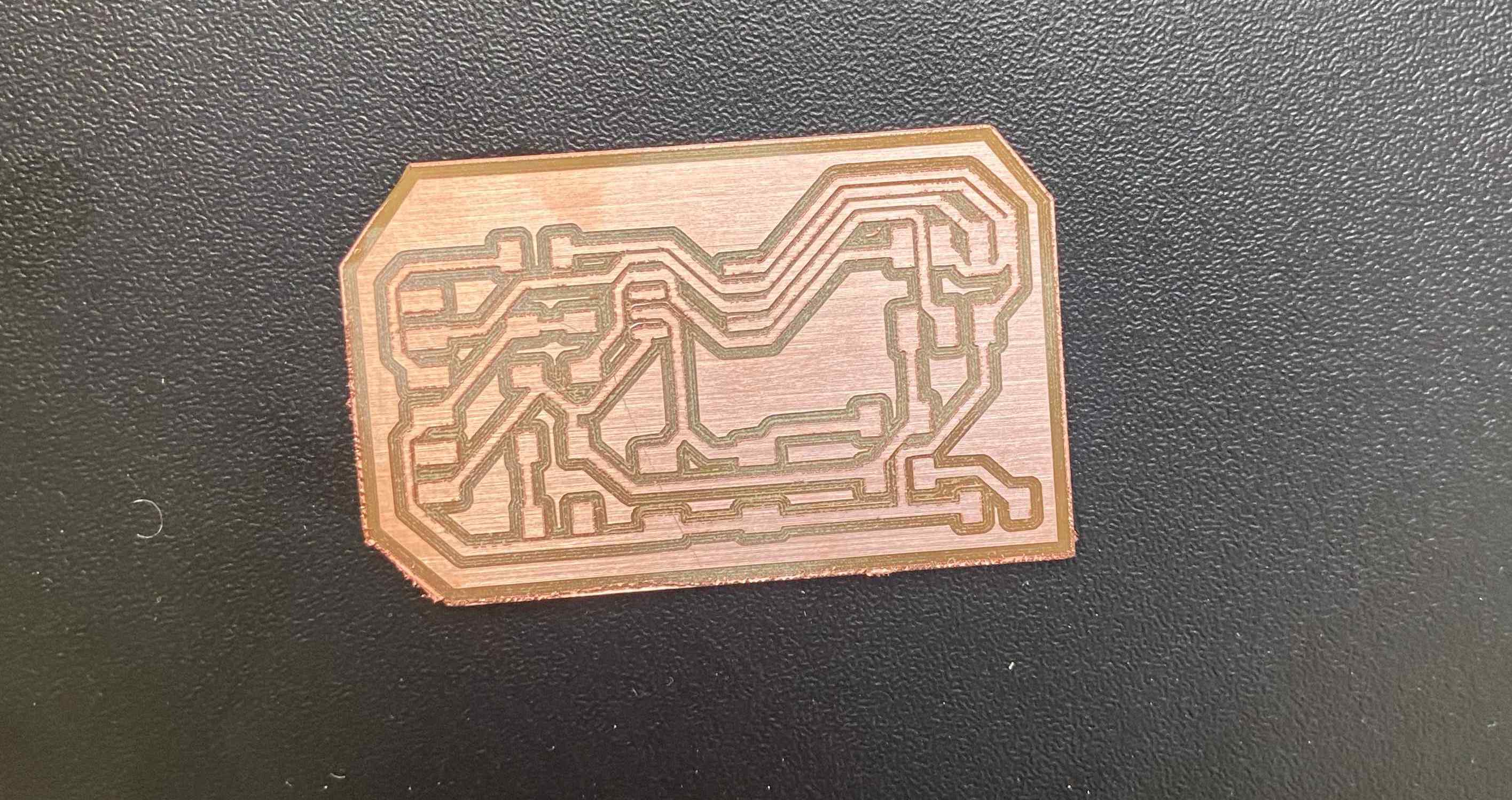
I started to drill again and managed to have my board!
👩🏽🏭 Soldering
I soldered the board with more ease this time since I had managed to practise quite a few in order to finish week05 assignment.
The finished look:
🥵 Will it work?
Once my board was ready, I connected to the FabISP with a jumper and the LED did not light up. Why, you may ask? Because the LED was not connected to the VCC. GOOD JOB ANDREA. So I decided to do this assignment again but with another board.
👩🏽🎤 Redrawing and a hello-world board
For the second attempt, I decided to design a All-in-1-board to do as many electronic assignments as possible. I decided to use an ATTINY44.
👩🏽🍳 EAGLE
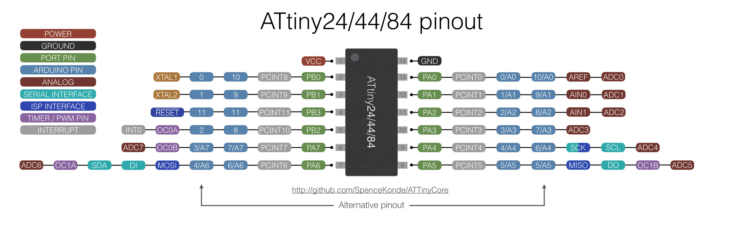
This board will include an ATtiny44, a potentiometer, a servo motor and a led. Here is the pinout of the ATTINY44.
👩🏽🍳 SCHEMATIC
I started directly to do the schematic by adding the attiny44, whose correct format is ATTINY44-SSU in EAGLE fab library. Following this step, I added the FTDI and the ISP (named CONN_03X2_AVRISPMD) and a 20MGh cristal. I directly connected these components to the attiny looking at the pinout, therefore I connected the cristal to pins PB1 and PB0 since they are XTAL1 and XTAL2. As far as FTDI and ISP are concerned, I connected RXD and TXD to PA1 and PA0 because I used this Neil’s example as reference. I connected also the MOSI, the MISO, the SCK and the RESET pins of the ISP to the directly correlated in the ATTINY44. I also put a capacitor of 1uF as Neil does in his example cited above.
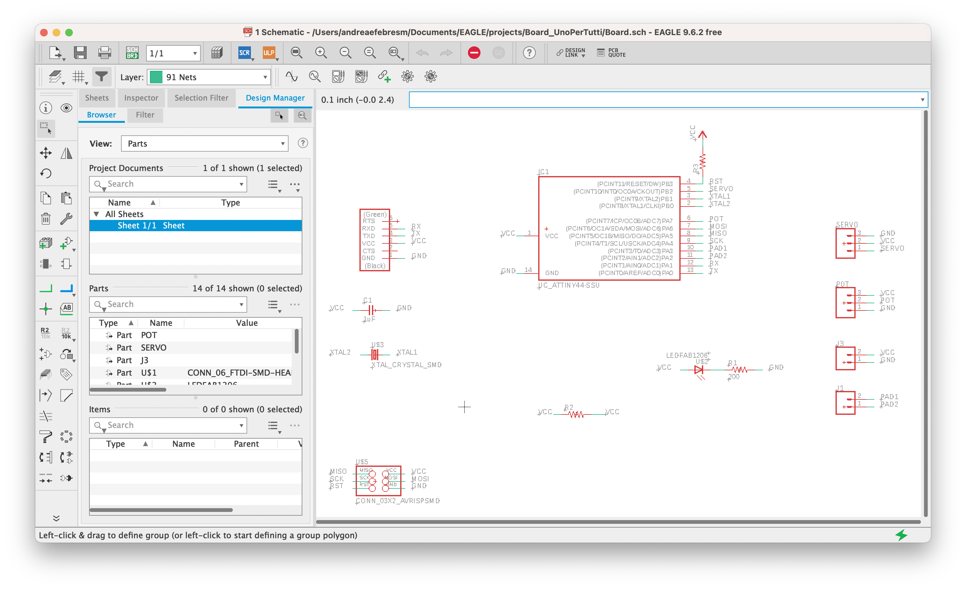
For the servo motor I added 3 pads: 1 pad for VCC, one pad for GND and one pad for the control pin. I did the same for the potentiometer and added also two pads for connectivity purposes. I net all the pads to the pins looking at the pinout for each component: * servo motor has GND, VCC and CONTROL. * potentiometer has VCC, CONTROL and GND.
I added also a LED that lights up when the board is connected, just to check everything works fine. To that LED I connected a 200ohm resistor.
Then I noticed I had two spare pins that I decided to connect to two pads, since I did not want to leave them empty.
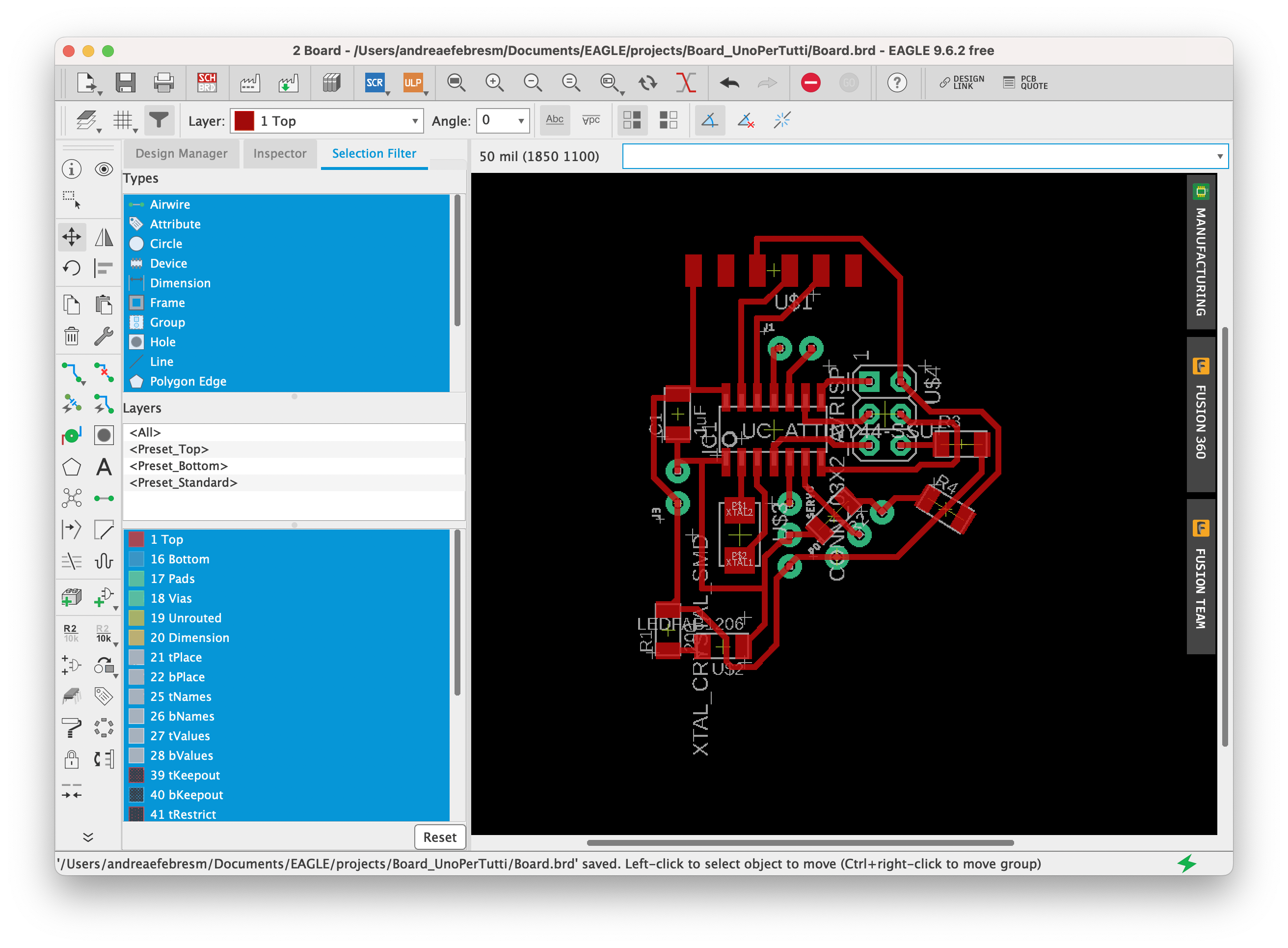
👩🏽🍳 BOARD
I switched to the board file in eagle and I started to arrange the components in the space. I tried with an autoroute first (with auto command) but I could get only 88% routes. So I started to arrange in the space the components again, trying to find a solution without usign 0ohm resistors but in the end I decided to use them.
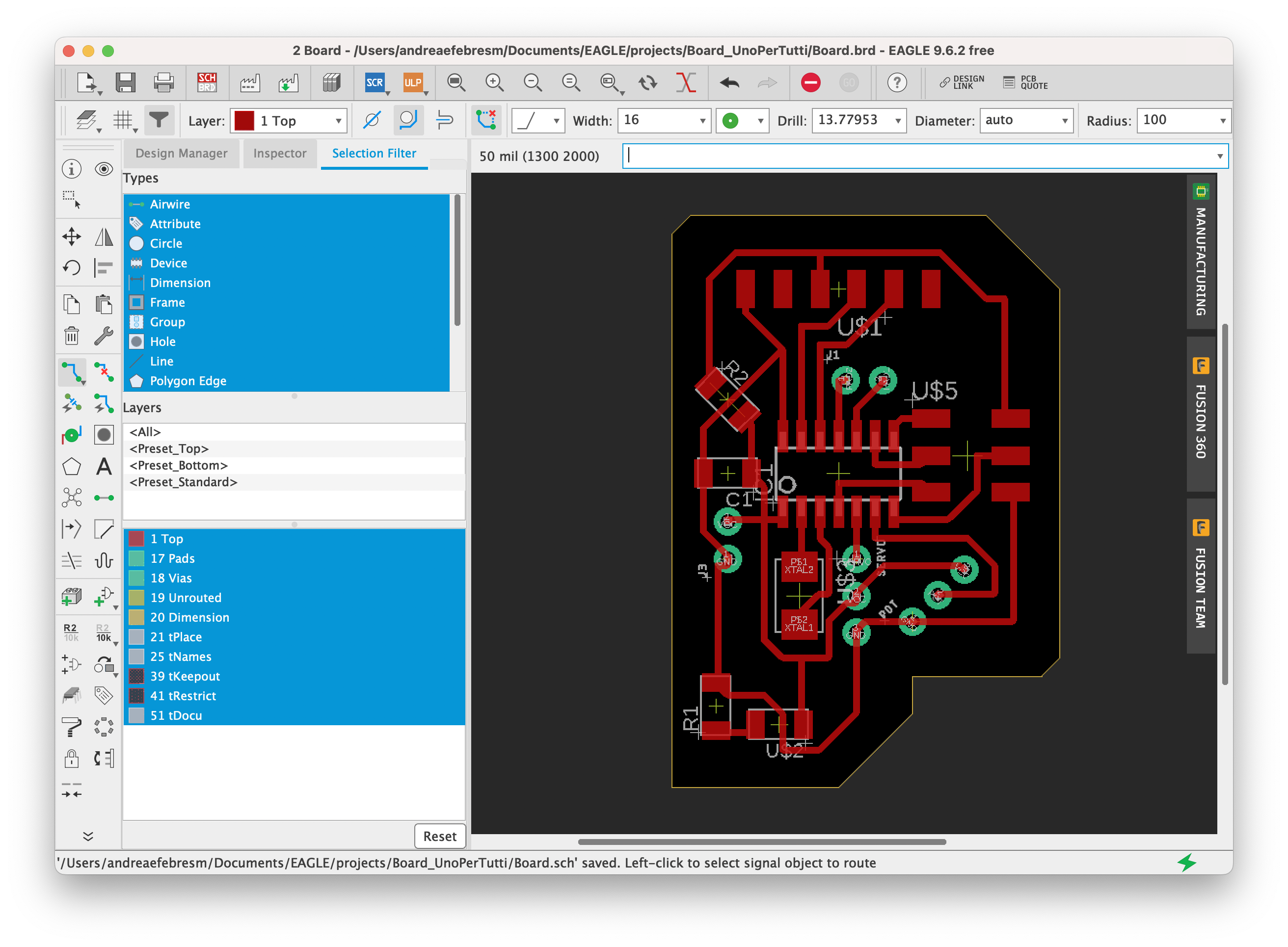
Here is the board with the routes (with 0.5mm Clearance and 16mil width in the Design Rules).
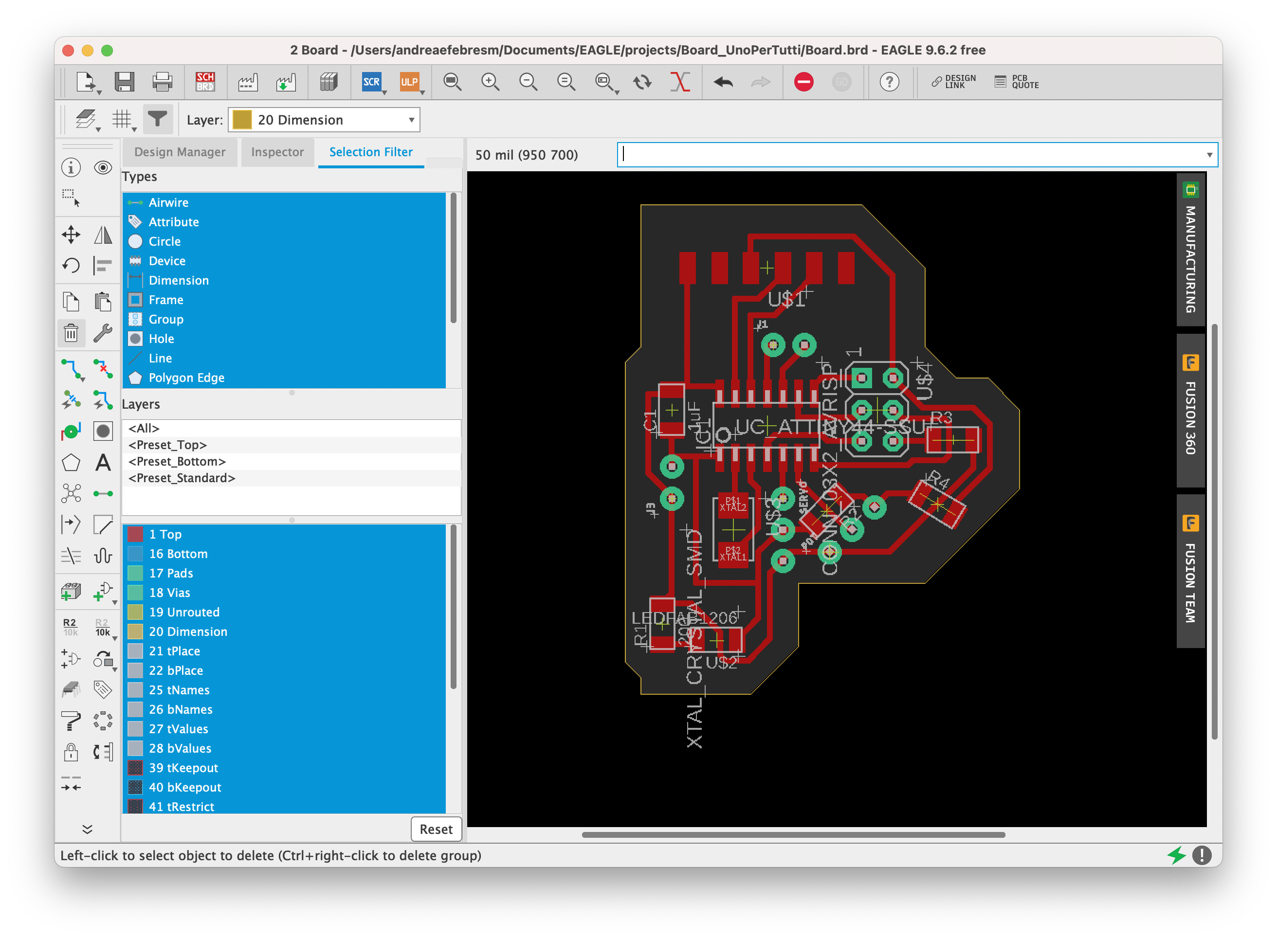
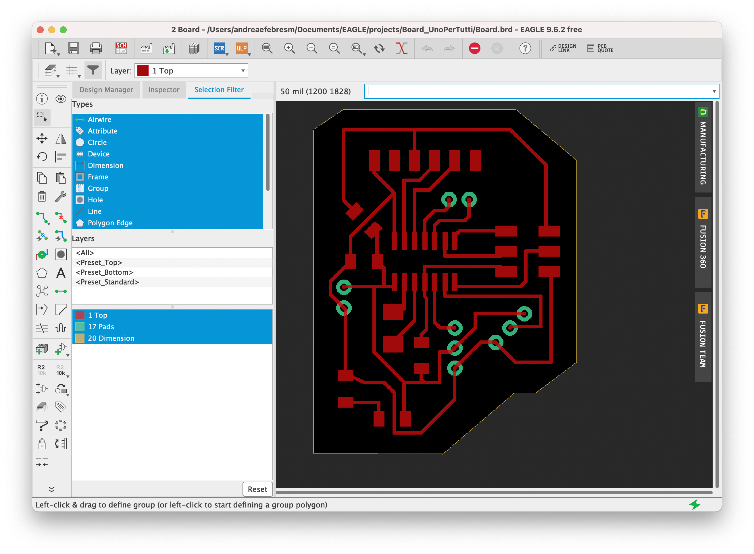
I then changed layer (in the top left corner there is the layer panel) and selected the 20 Dimension layer, which is the yellow one. I wrote line in the command bar and drew a line as a border for my board.
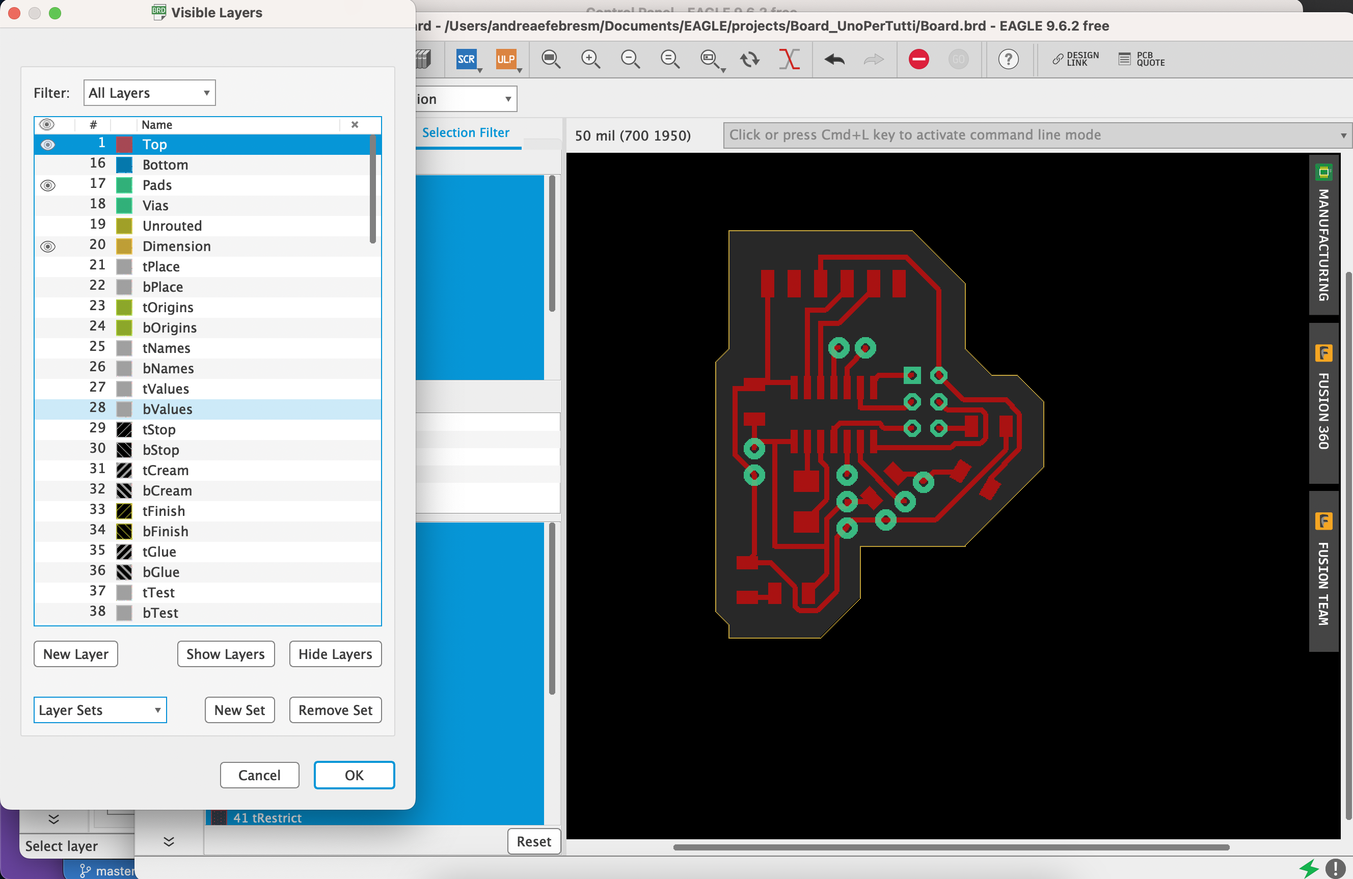
I went to the layers panel and selected all the layers (with Command+A) and then Hid them all. Then I clicked on Top, Pad and Dimensions to show only these layers for export matters.
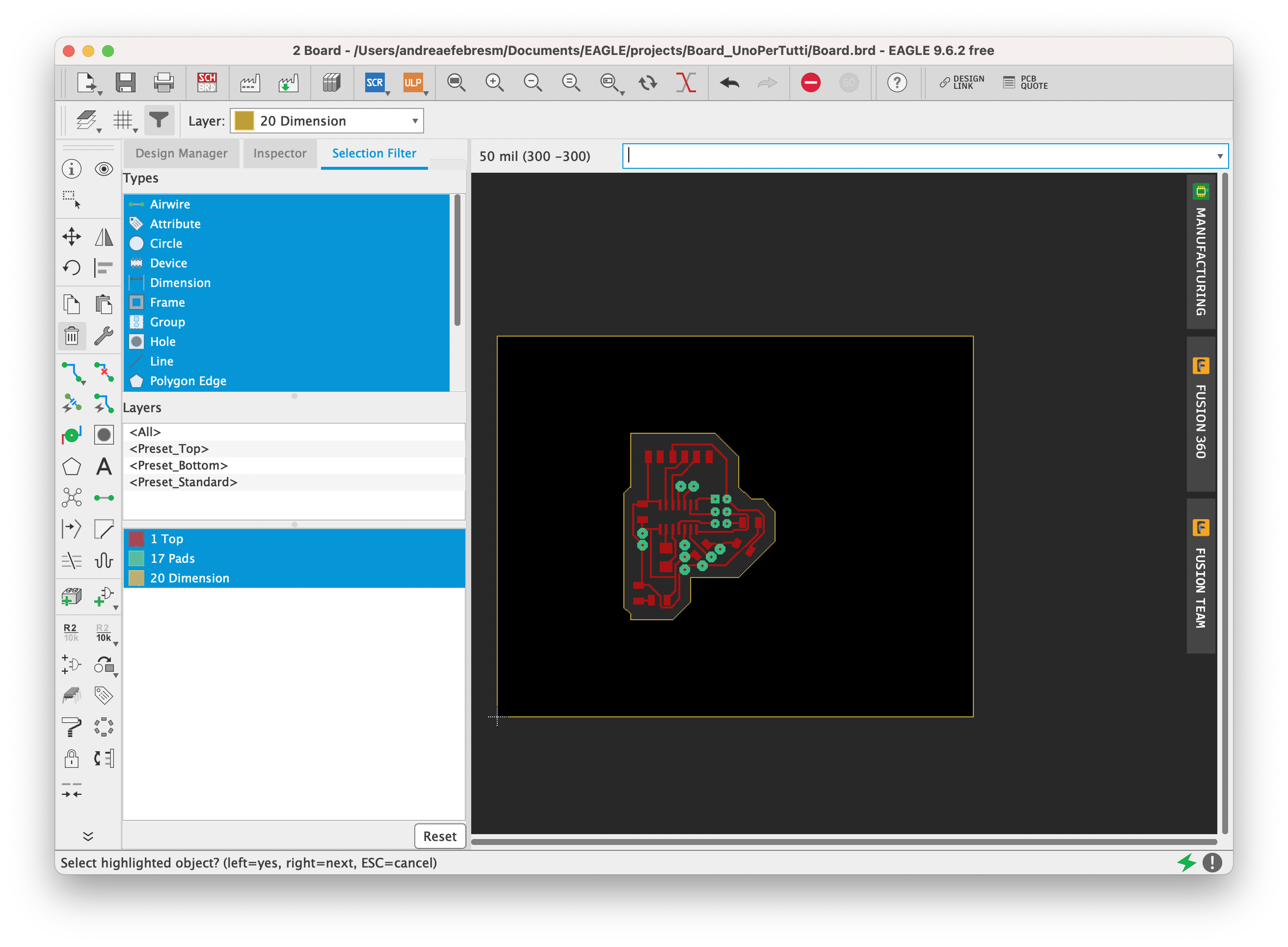
Lastly, I zoomed out and selected the yellow rectangle that made my black background and deleted it because if you don’t delete it, then you will export the whole rectangle and not only the board.
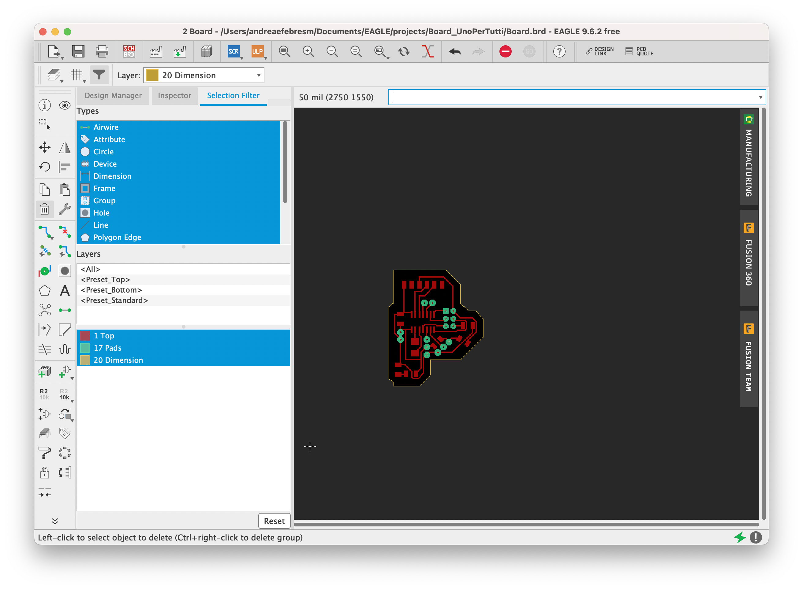
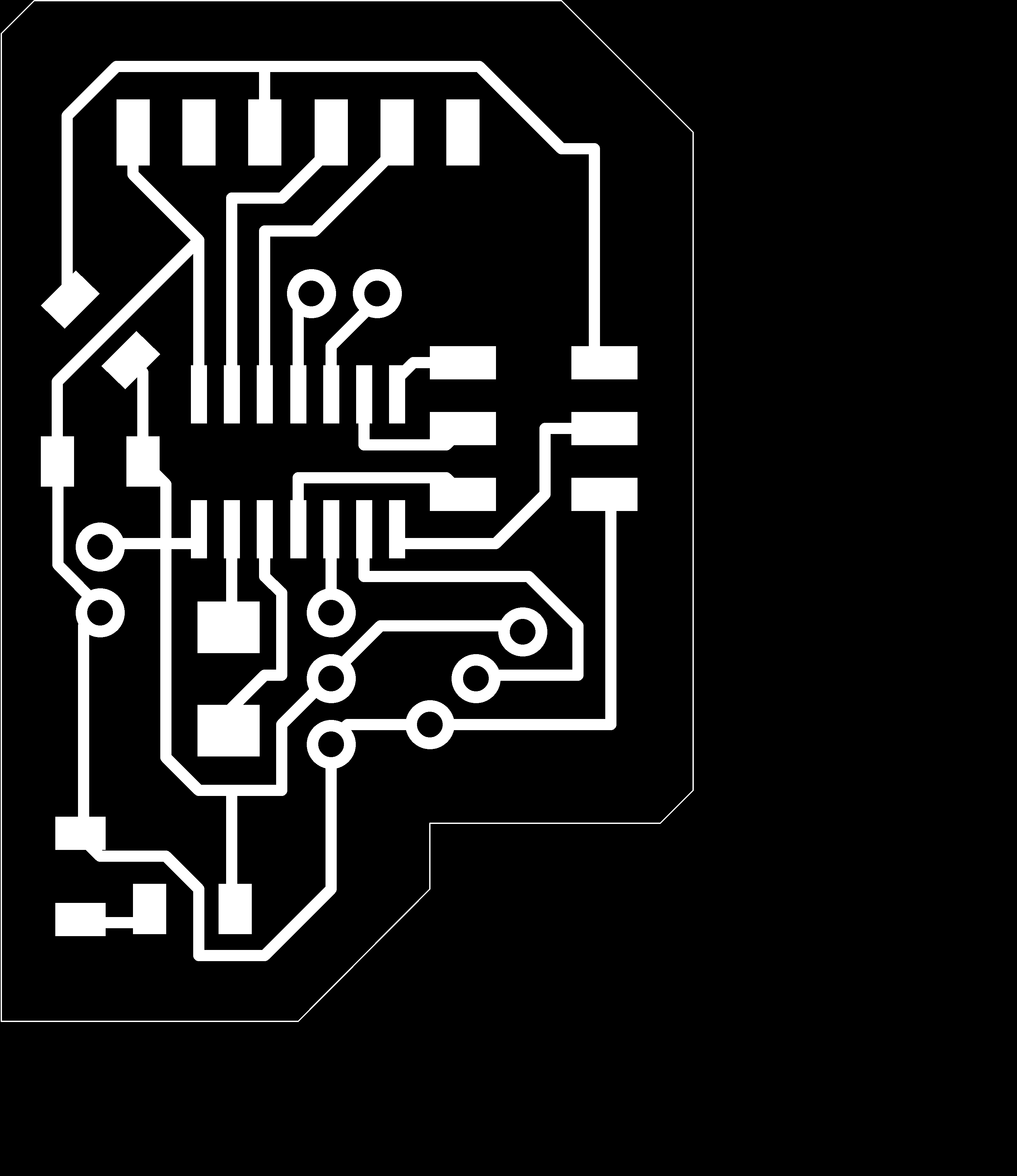
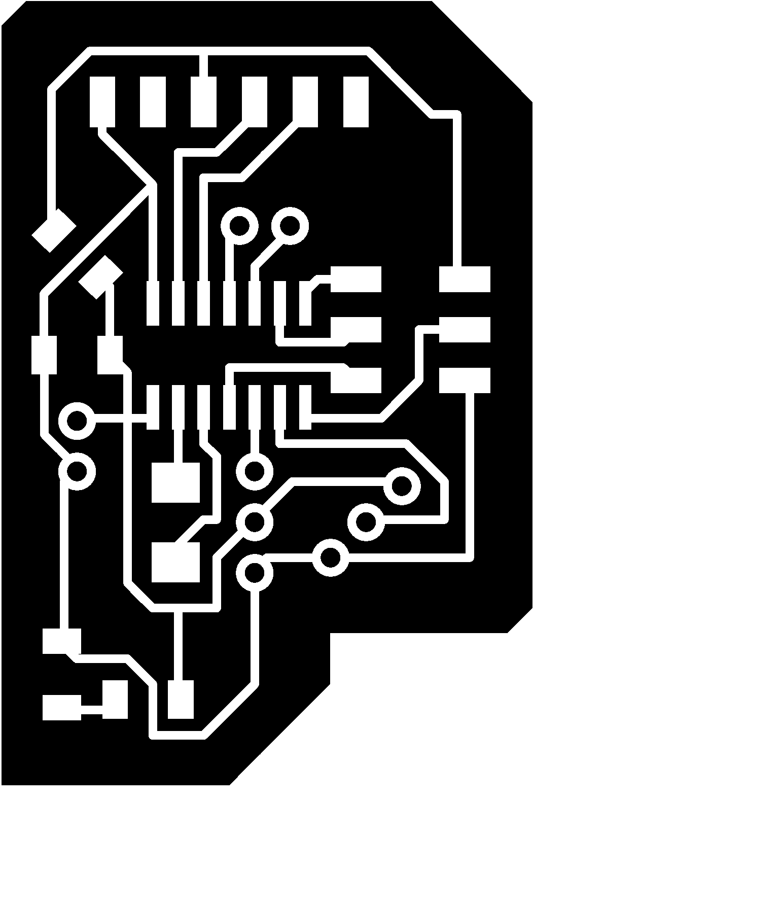
I then went to File > Export > Image and I browsed to my folder to save the image. I selected monochrome and set the dpi to be 1000. I saved the image that is this:
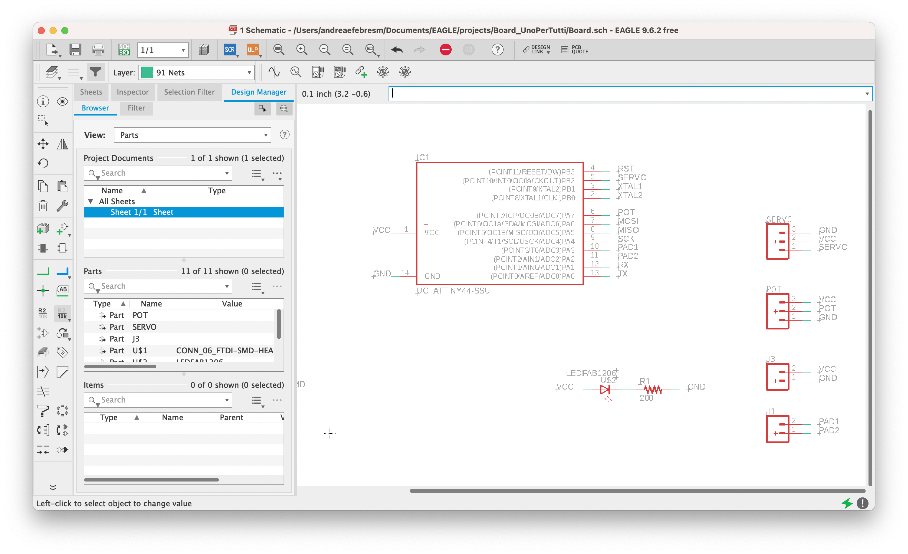
Once I exported the image, I noticed that the ISP was not the correct one so I changed it with the right one:
I then notices that I was missing a pull up resistance. Here is the updated board.
🫐 FabModules _ 2
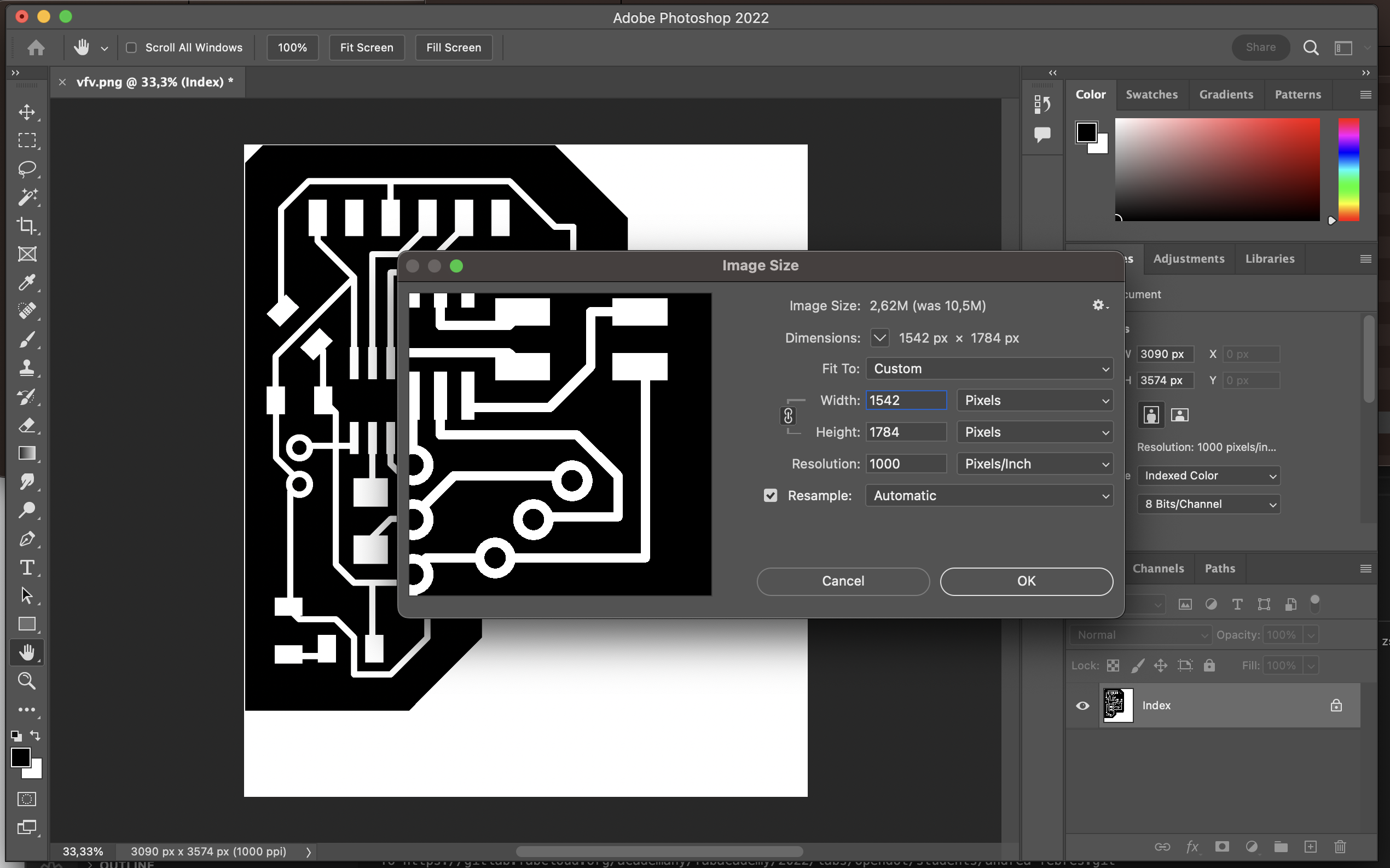
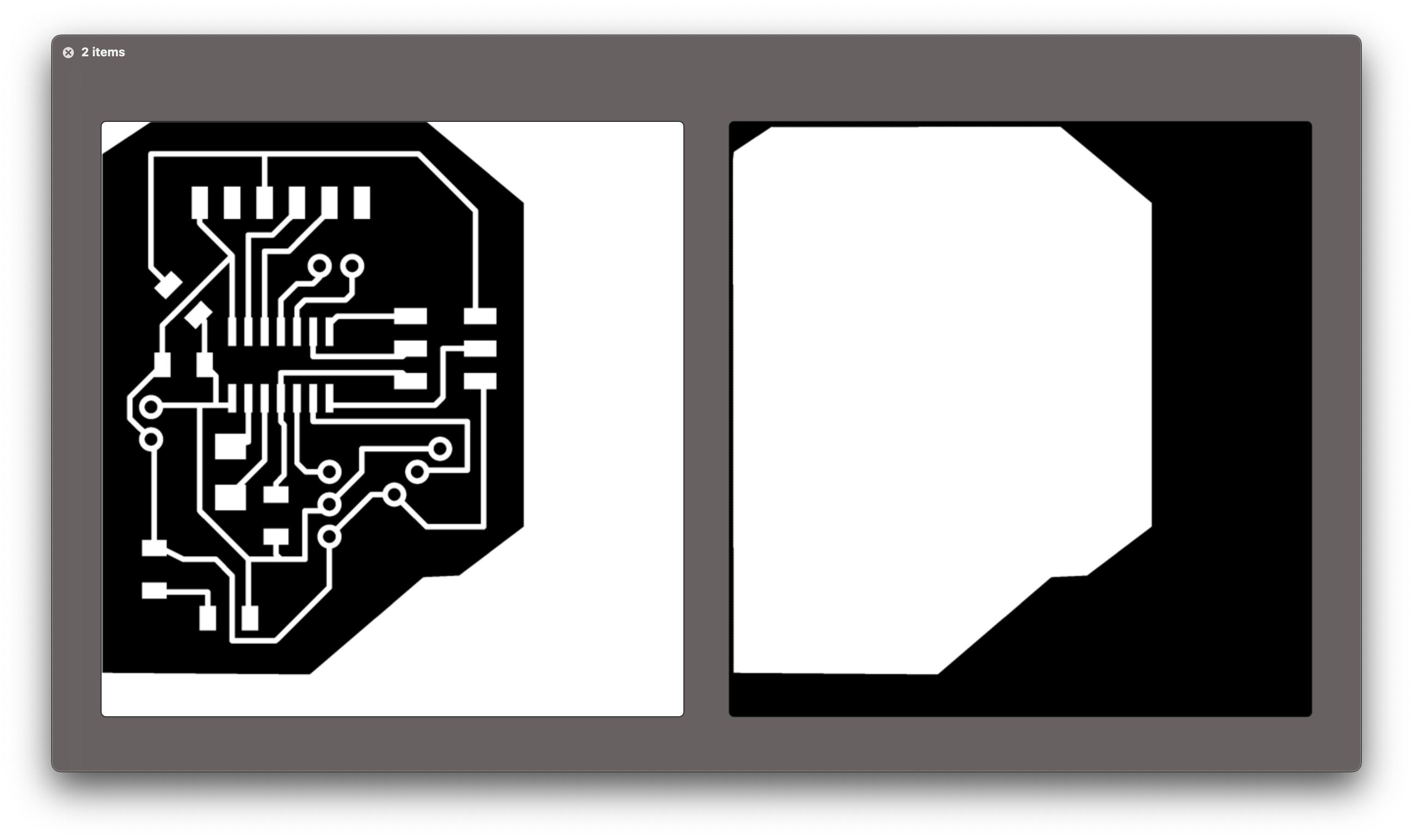
Before going in fab modules, I opened the png in Photoshop and separated the traces from the outline.
I checked that the dimensions of the image were correct since EAGLE has a bug with MacOS and exports the image at the double of the size.
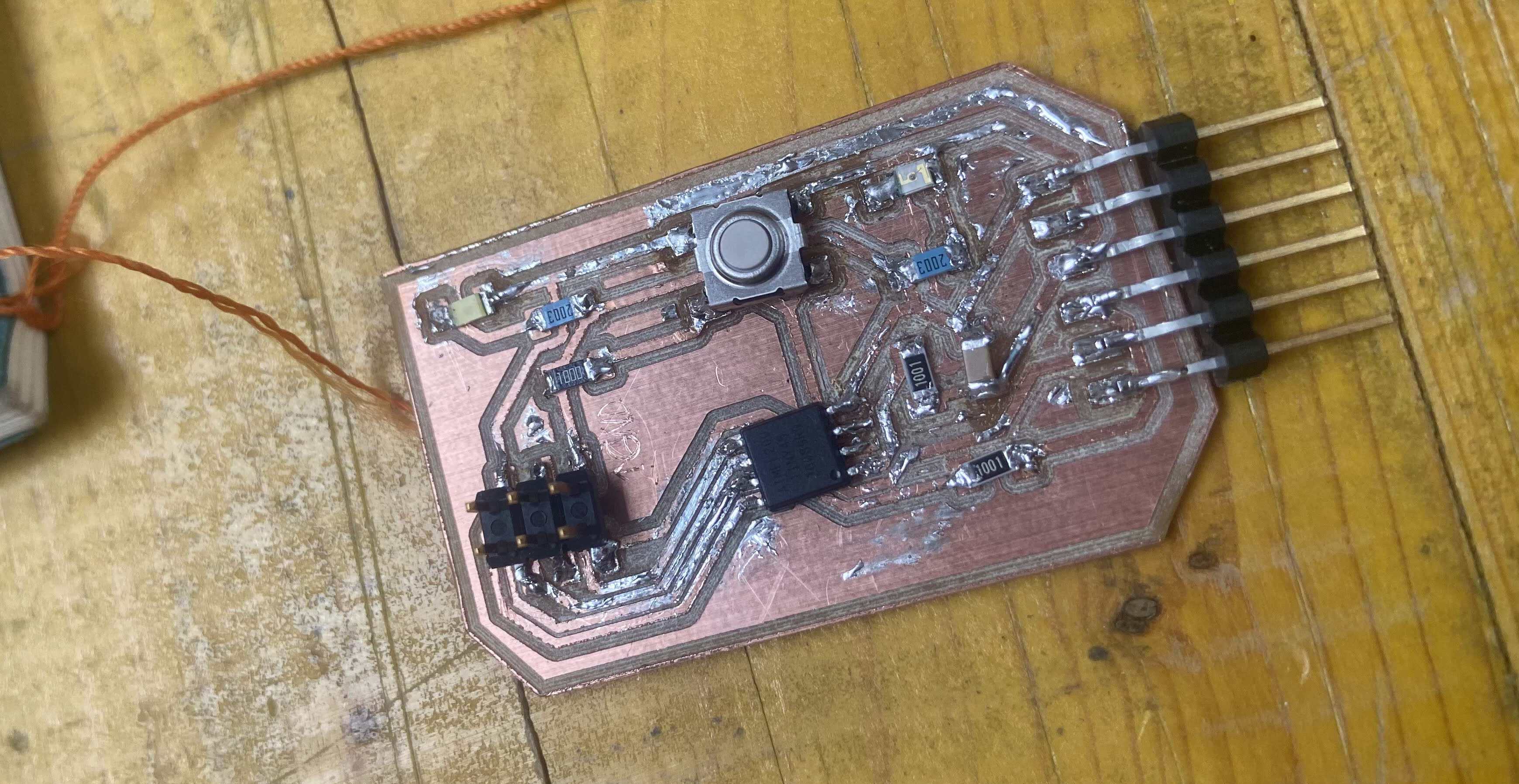
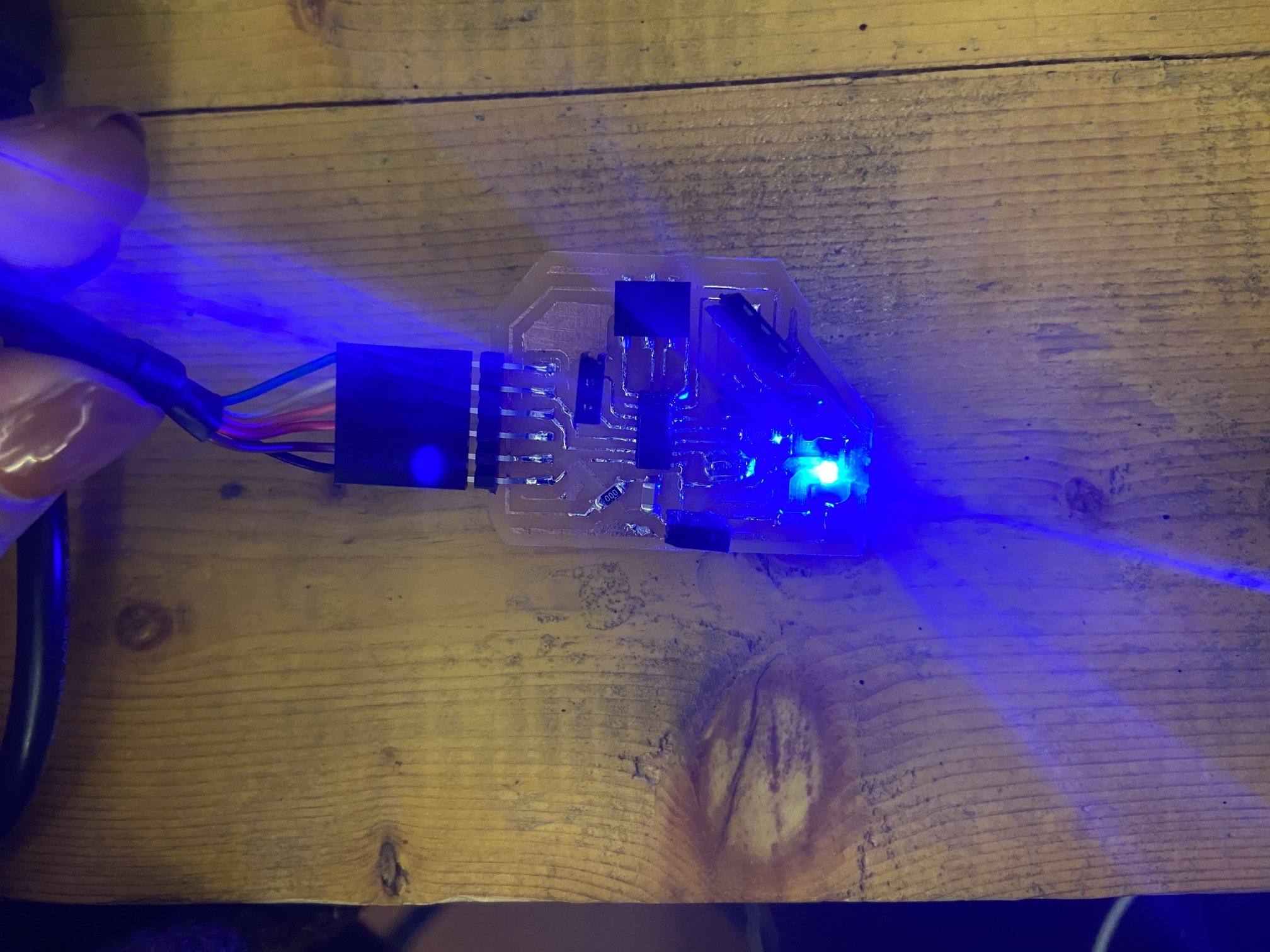
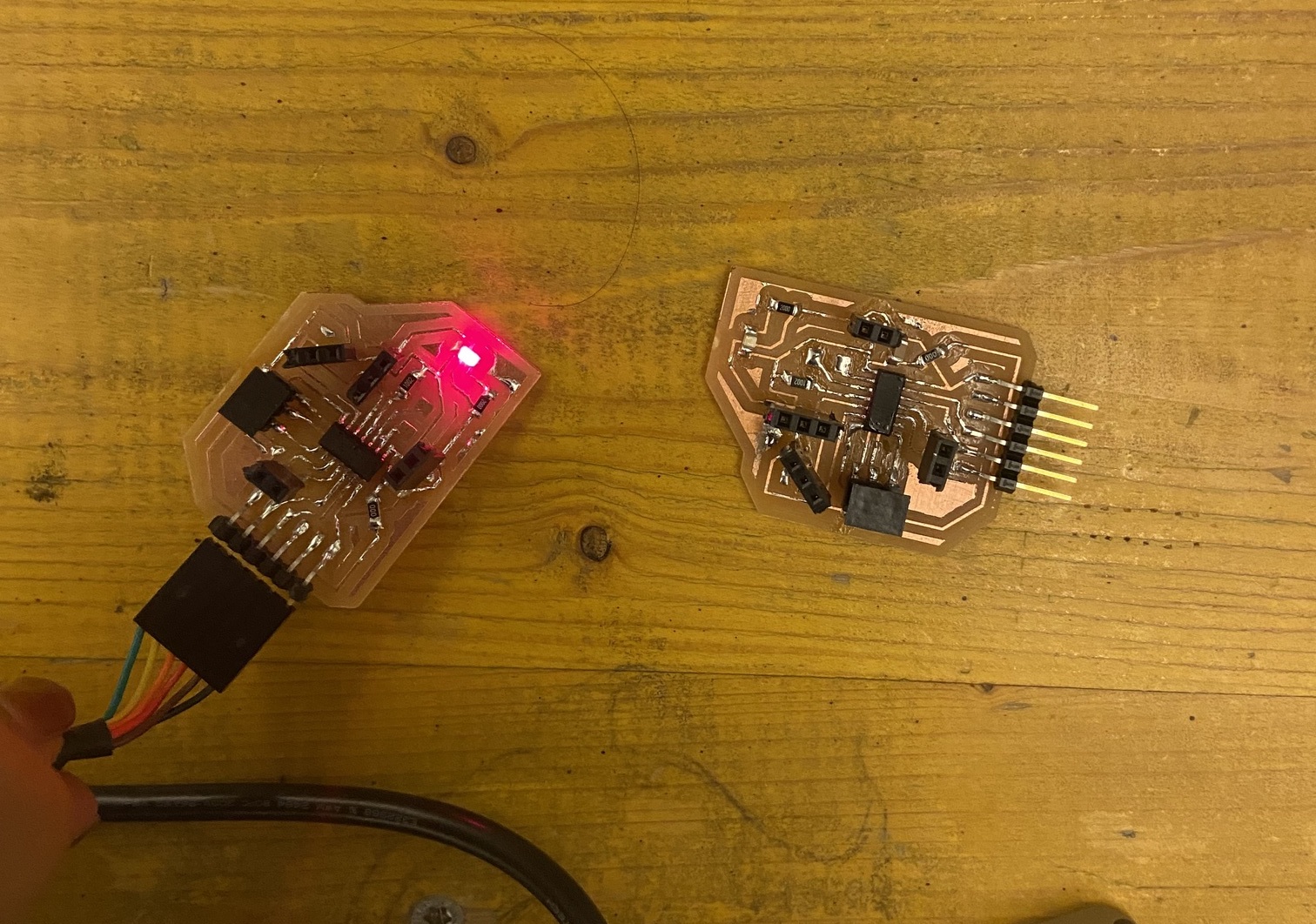
I then did the same process I explained before here and started milling as explained here. I soldered the board and here is the final result:
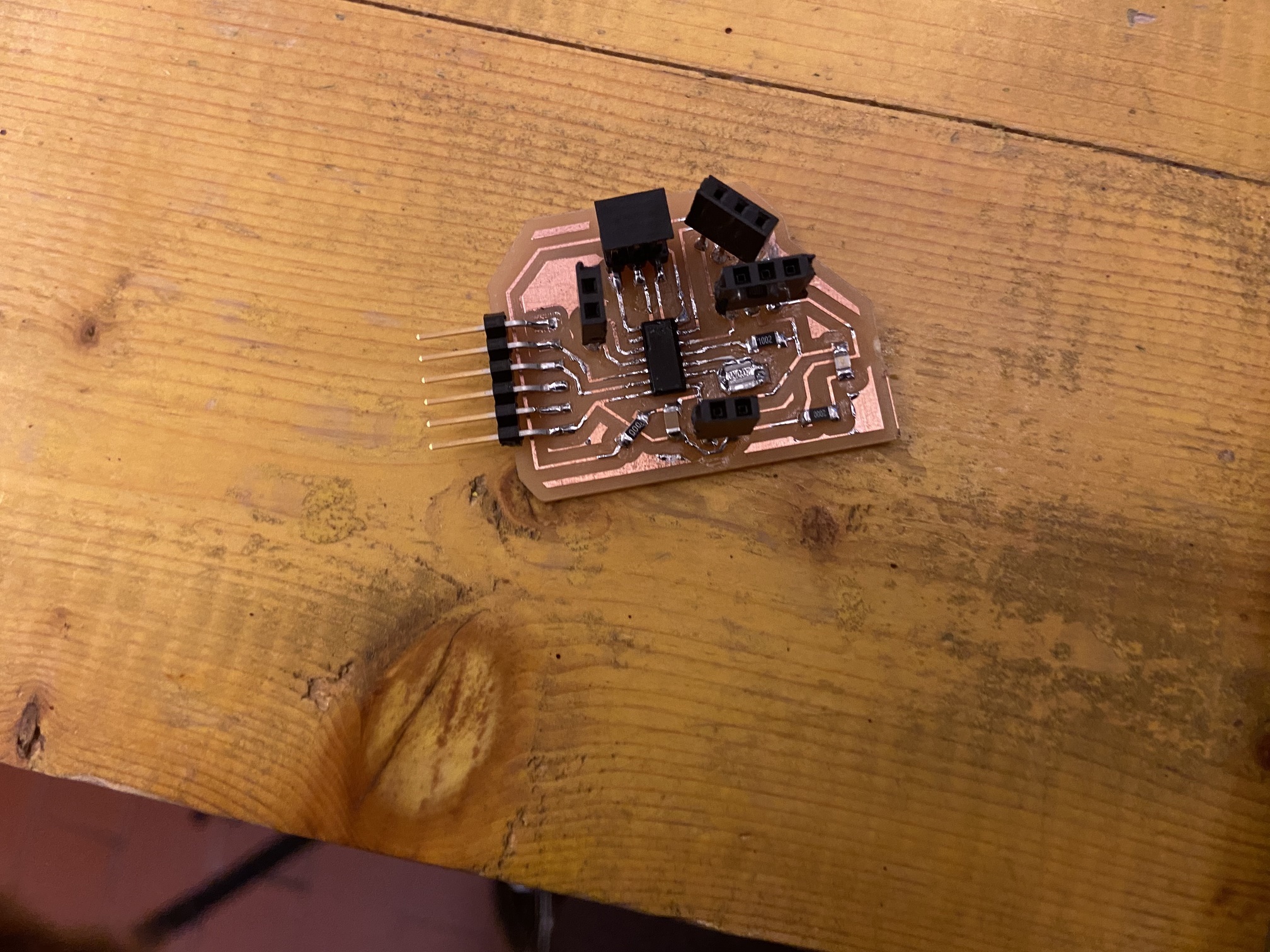
And when connected the led lights up, so it works!
I did another one just to be sure.
🐏 Program
In order to program the board, I opened Arduino IDE. I explained how to install and prepare the pipe of programming in Embedded programming.
I then proceeded in create this code to make a servo move. I defined the delay time as an int variable and the pin for the Servo as servoPin.
int d = 100; //delay time
int servoPin =  8; //pin PB2
I then attached the servo to the pin with pinMode in the setup
void setup() {
  pinMode(servoPin, OUTPUT);
}
And in the loop I made the servo sweep with analogWrite.
void loop() {
  analogWrite(servoPin, 10);
  delay(1000);
  analogWrite(servoPin, 250);
  delay(1000);
}
here is the full code.
int d = 100; //delay time
int servoPin =  8; //pin PB2

void setup() {
  pinMode(servoPin, OUTPUT);
}

void loop() {
  analogWrite(servoPin, 10);
  delay(d);
  analogWrite(servoPin, 250);
  delay(d);
}
I compiled this code with COMMAND + R to see if there was any error in the code.
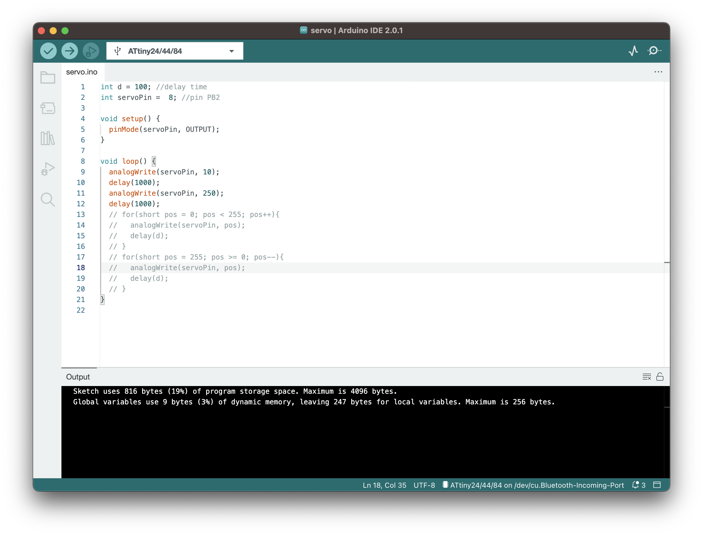
Since everything was fine ( in the Output there is written
Sketch uses 816 bytes (19%) of program storage space. Maximum is 4096 bytes. Global variables use 9 bytes (3%) of dynamic memory, leaving 247 bytes for local variables. Maximum is 256 bytes. )
The board, in the meantime, was connected to a programmer:
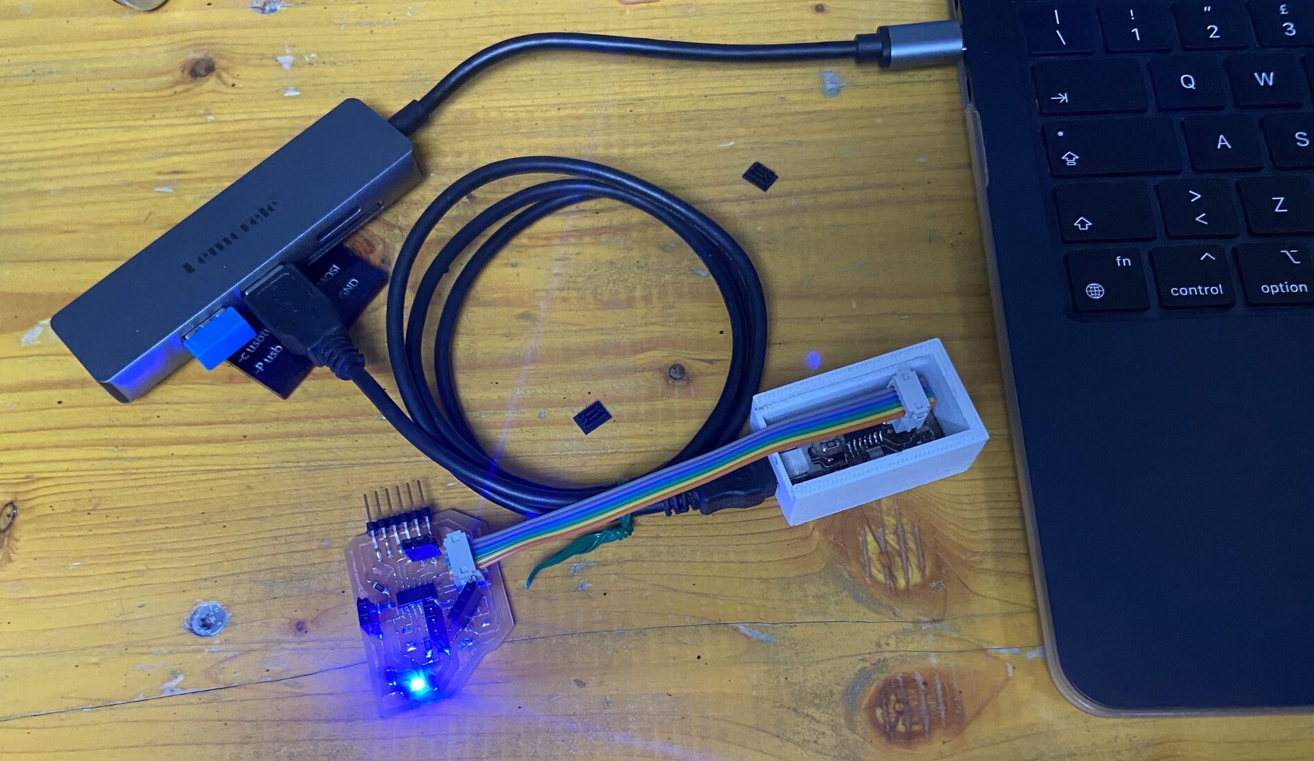
I proceeded to upload the program to the board. To do so, I did the following steps:
- Select the port
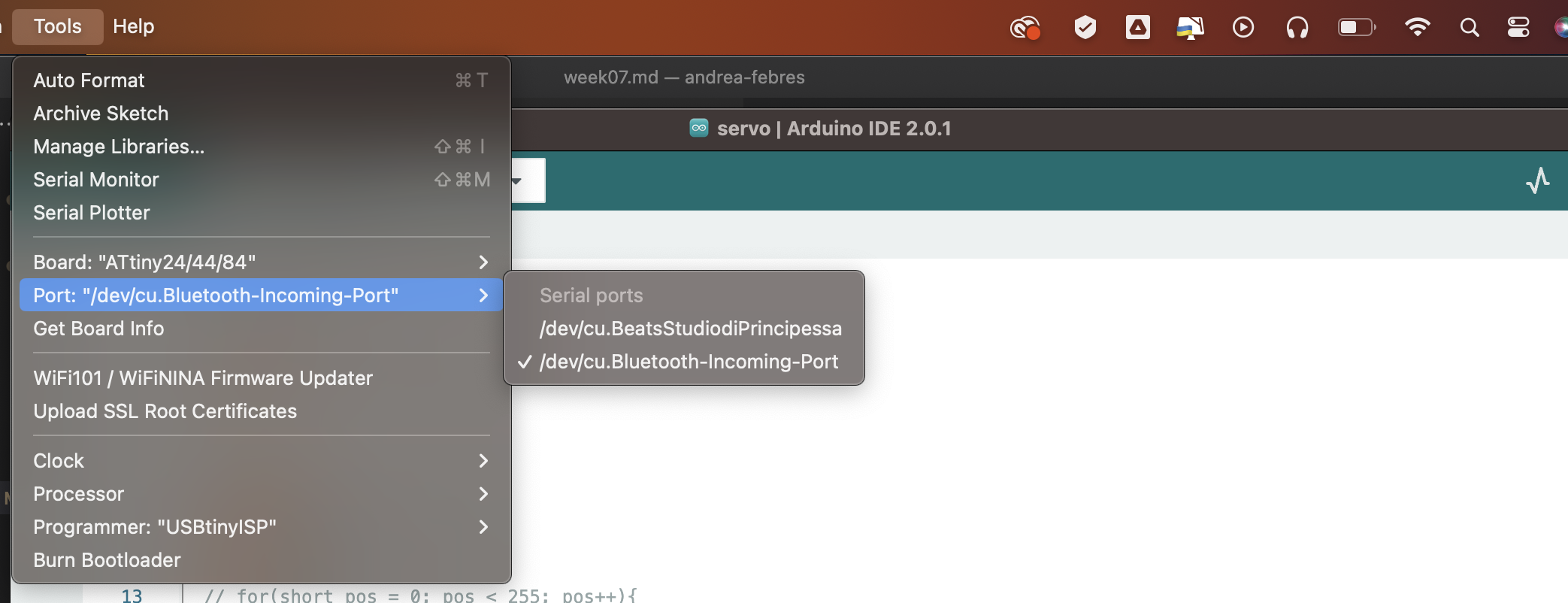
- Select the clock (the attiny44 has 8MHz)
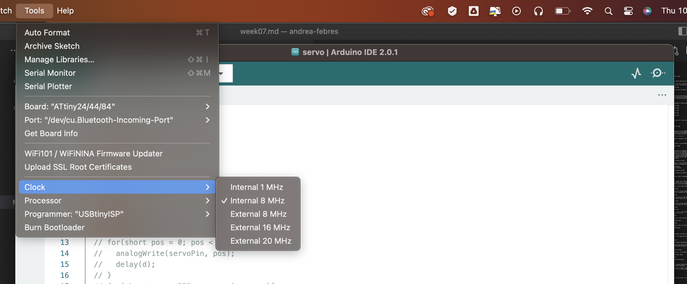
- Choose the processor (ATtiny44)
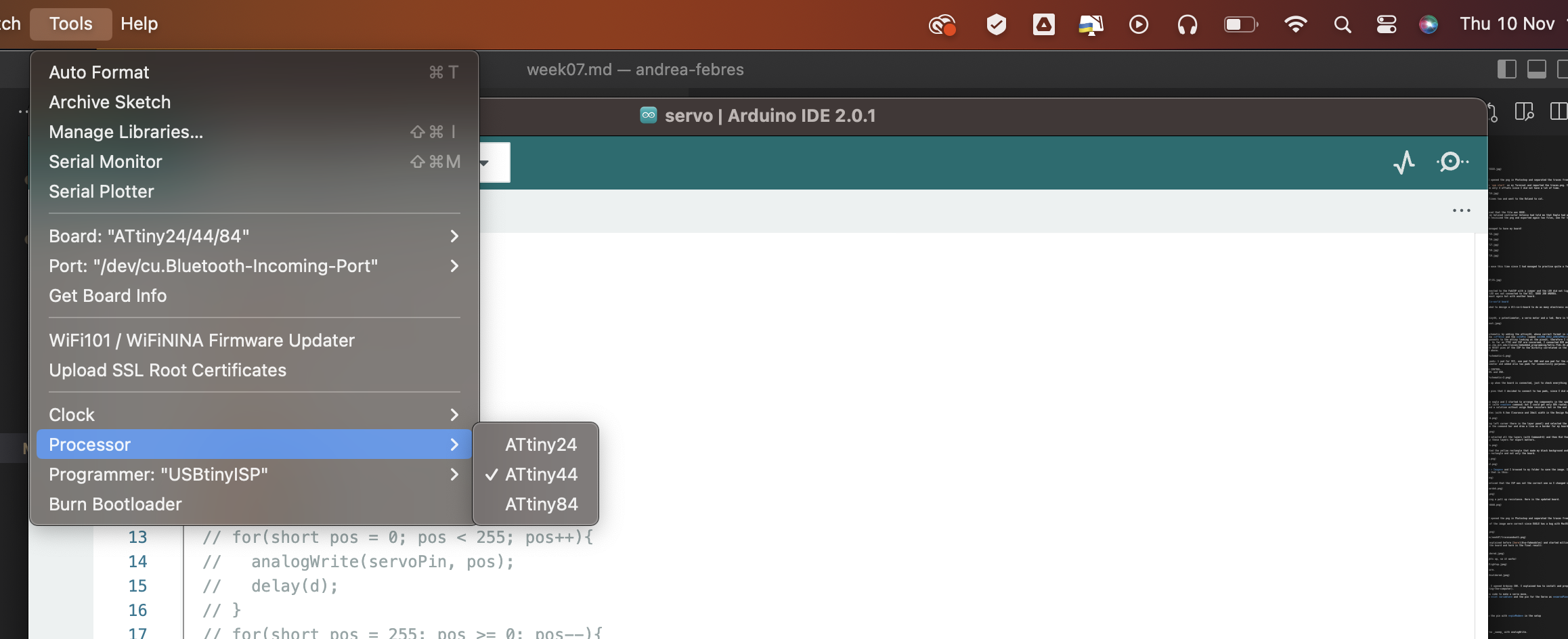
- Choose the programmer (USBtinyISP)
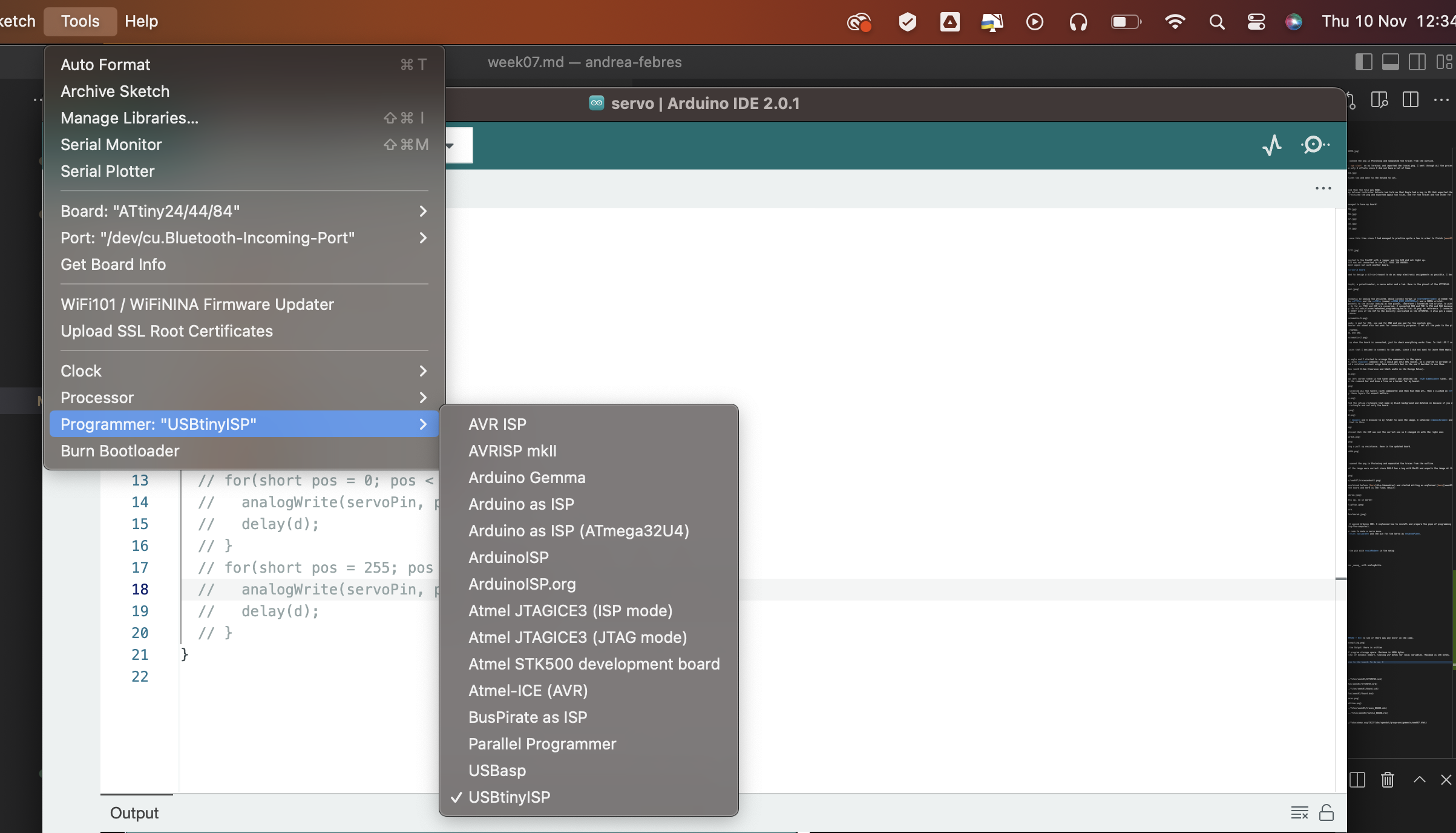
Once I did this, I uploaded the program using a programmer. This is important because if you upload directly it won’t work. To upload using a programmer you can both do Sketch > Upload using a Programmer or do Command + SHIFT + U.
Done this, the servo started to move.