9. Embedded programming
- Read the datasheet for your microcontroller
- Use your programmer to program your board to do something
💩 Datasheet for my microcontroller
The board I designed in Electronic design had an ATtiny45 as microcontroller.
👽 It’s important to give name to things
🫰🏽 Microcontrollers
To start off, I had to look out what a microcontroller was.
A microcontroller is a complete programmable circuit, capable of executing the orders recorded in its memory. It is composed of several functional blocks that fulfill a specific task. A microcontroller includes within it the three main functional units of a computer: microprocessor, memory, and input/output peripherals.
Essentially, a microcontroller gathers input, processes this information, and outputs a certain action based on the information gathered. Microcontrollers usually operate at lower speeds, around the 1MHz to 200 MHz range, and need to be designed to consume less power because they are embedded inside other devices that can have greater power consumptions in other areas.
👌🏽 Microprocessors
A Microprocessor is an electronic component that is used by a computer to do its work. It is a central processing unit on a single integrated circuit chip containing millions of very small components including transistors, resistors, and diodes that work together. Some microprocessors in the 20th century required several chips. Microprocessors help to do everything from controlling elevators to searching the Web. Everything a computer does is described by instructions of computer programs, and microprocessors carry out these instructions many millions of times a second.
👾 Preparing the computer
First of all, I started by downloading ArduinoIDE from the Terminal in my pc with this command:
brew install --cask arduino
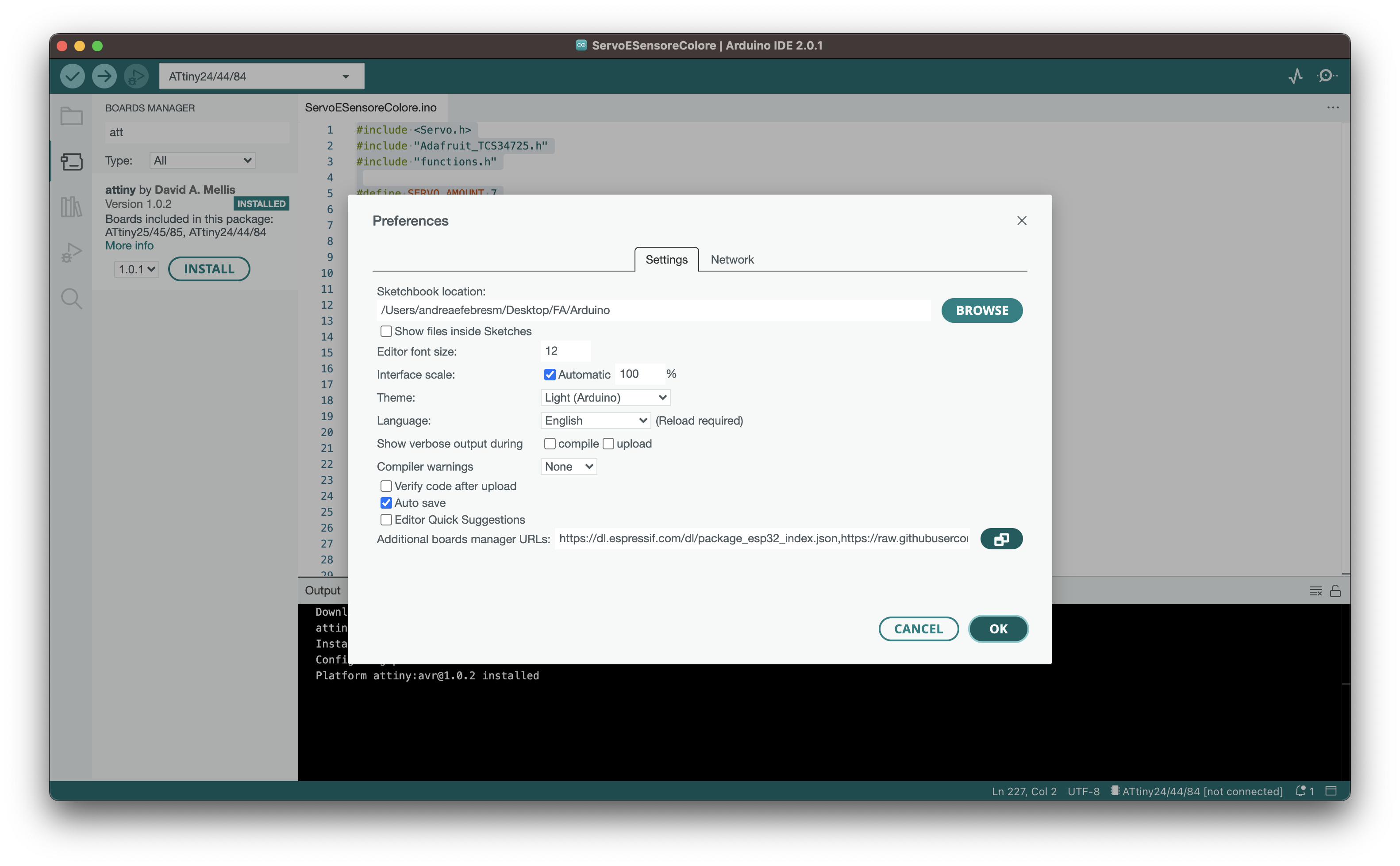
After the installation was done, I proceeded opening arduino ide and added the board processor for ATTINY. I did so by opening the preferences in Arduino IDE
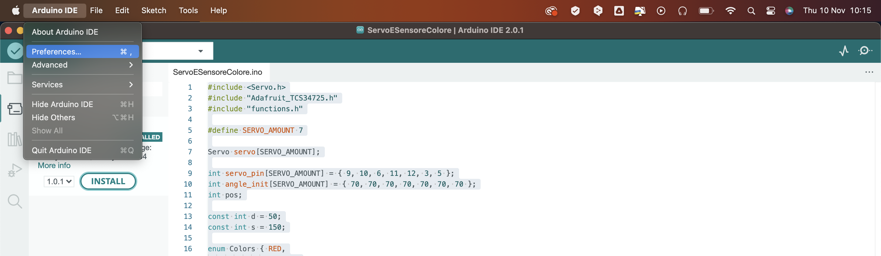
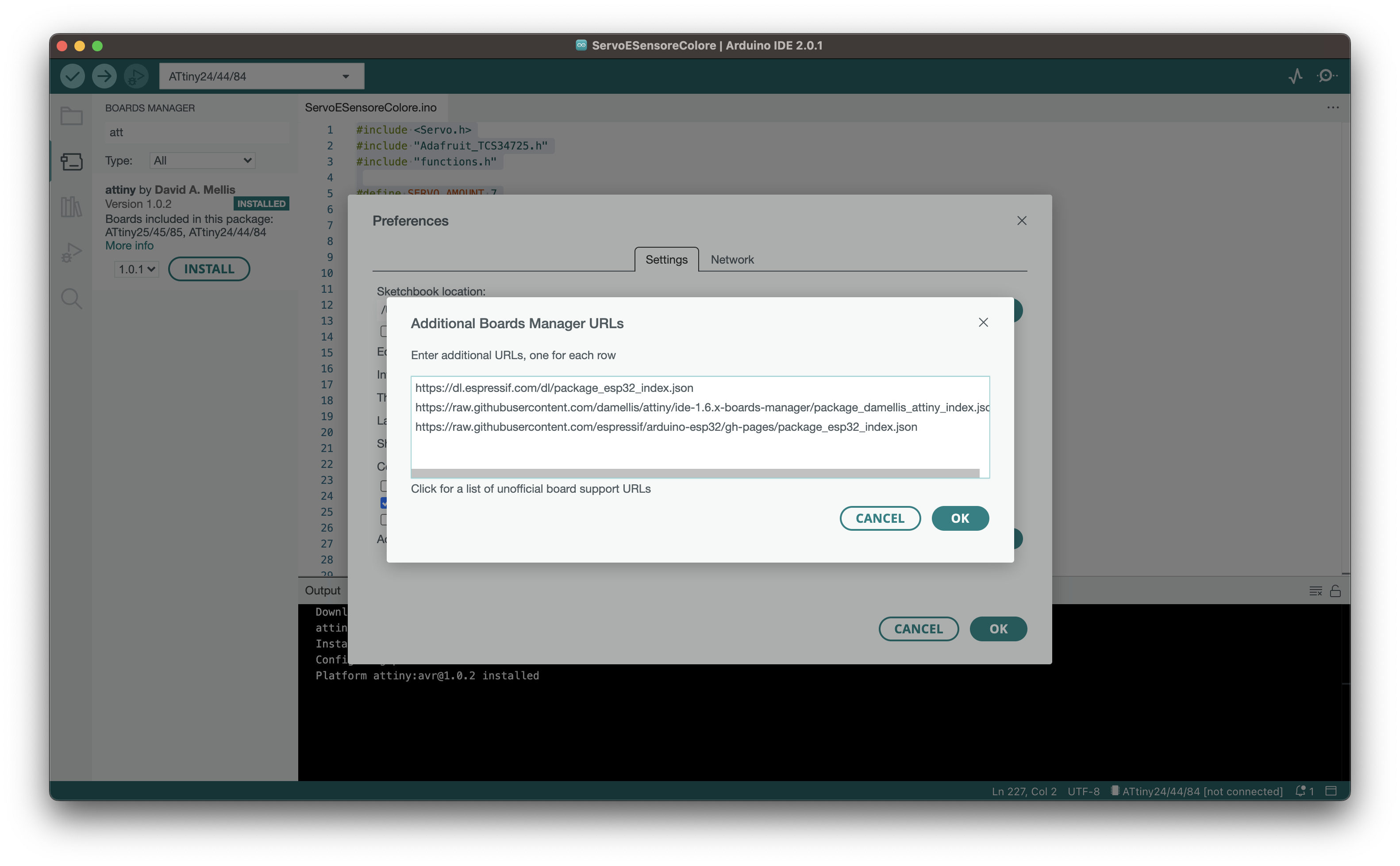
and clicked on Additional Boards Manager URLs.
I then pasted the following url.
https://raw.githubusercontent.com/damellis/attiny/ide-1.6.x-boards-manager/package_damellis_attiny_index.json
I then could open the board manager that you can find in Tools > Board > Board Manager (or using the shortcut SHIFT+COMMAND+B in MacOS)
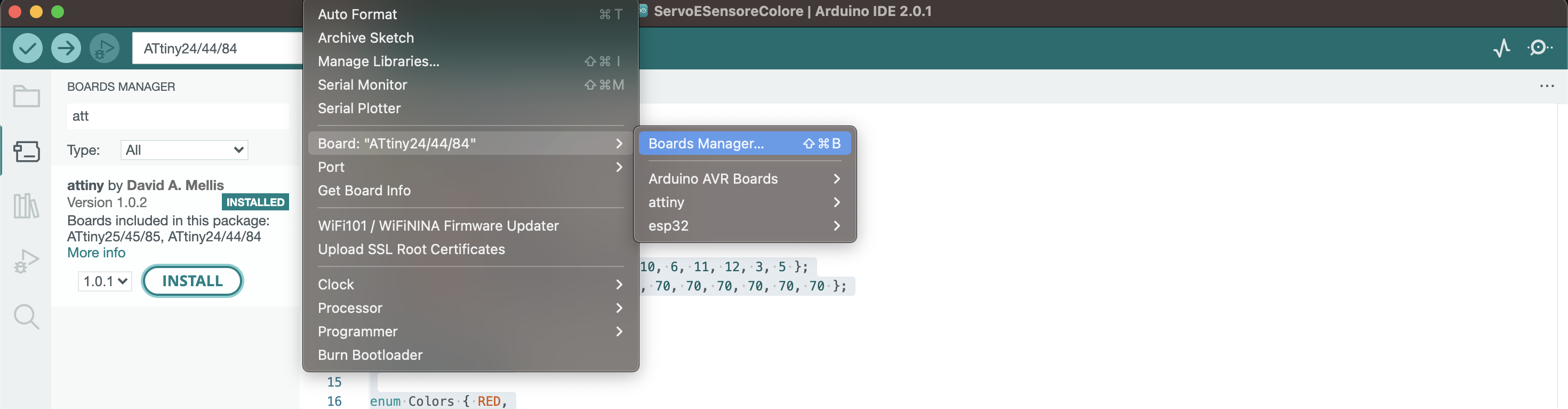
and clicked on INSTALL.
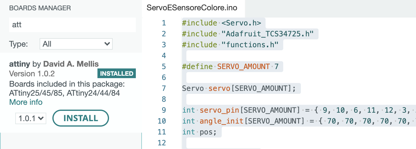
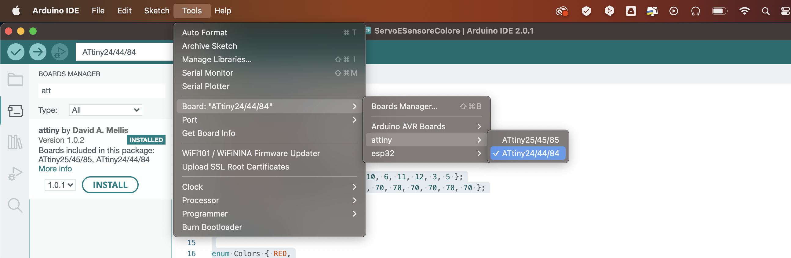
Now that I have the board installed, I can select it in BOARD as follows:
🛸 Let’s get digital
Before writing the code in arduino IDE, I wanted to test the code in TinkerCAD. TinkerCAD is a free, web based CAD tool for 3D modeling and circuit simulation that allows you, indeed, to build and simulate a circuit without ruining your board (eheh).
Since I did not have any previous knowledge of coding, I started off with something simple: turning on a led when the switch was pressed and viceversa. I first selected in TinkerCAD the arduino UNO board, a led and a switch and two resistors.
I wrote the code and tested it, and it worked. I then tried to “complicate” the code by making the led blink after 5 button presses:
int led = 13;
int but = 2;
int butPress = 0;

void setup() {
  pinMode(led, OUTPUT);
  pinMode(but, INPUT);
  Serial.begin(9600);
}

void loop() {

 if (digitalRead(but)) {
    butPress = butPress + 1;
    delay(250);
  }

  if (butPress == 5) {
    digitalWrite(led, !digitalRead(led));
    delay(299);
  } else if (butPress > 5) {
    butPress = 0;
    digitalWrite(led, !digitalRead(led));
  }
  delay(500);
  Serial.print("Button was pressed");
  Serial.println(butPress);
}
💩 Datasheet for my microcontroller - AGAIN
FLASHBACK TO ELECTRONIC DESIGN.
Once my board was ready, I connected to the FabISP with a jumper and the LED did not light up. Why, you may ask? Because the LED was not connected to the VCC. GOOD JOB ANDREA. So I decided to do this assignment again but with another board.
I designed a board with an ATtiny44 in order to do as much electronic assignments as I could.
ATtiny44
The ATtiny44 is a low-power CMOS 8-bit microcontroller based on the AVR enhanced RISC architecture. By executing powerful instructions in a single clock cycle, the ATtiny44 achieves throughputs approaching 1 MIPS per MHz allowing the system designer to optimize power consumption versus processing speed. The AVR core combines a rich instruction set with 32 general purpose working registers. All the 32 registers are directly connected to the Arithmetic Logic Unit (ALU), allowing two independent registers to be accessed in one single instruction executed in one clock cycle. The resulting architecture is more code efficient while achieving throughputs up to ten times faster than con- ventional CISC microcontrollers.
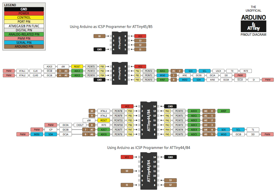
Here you can find the pinout of the attiny44:
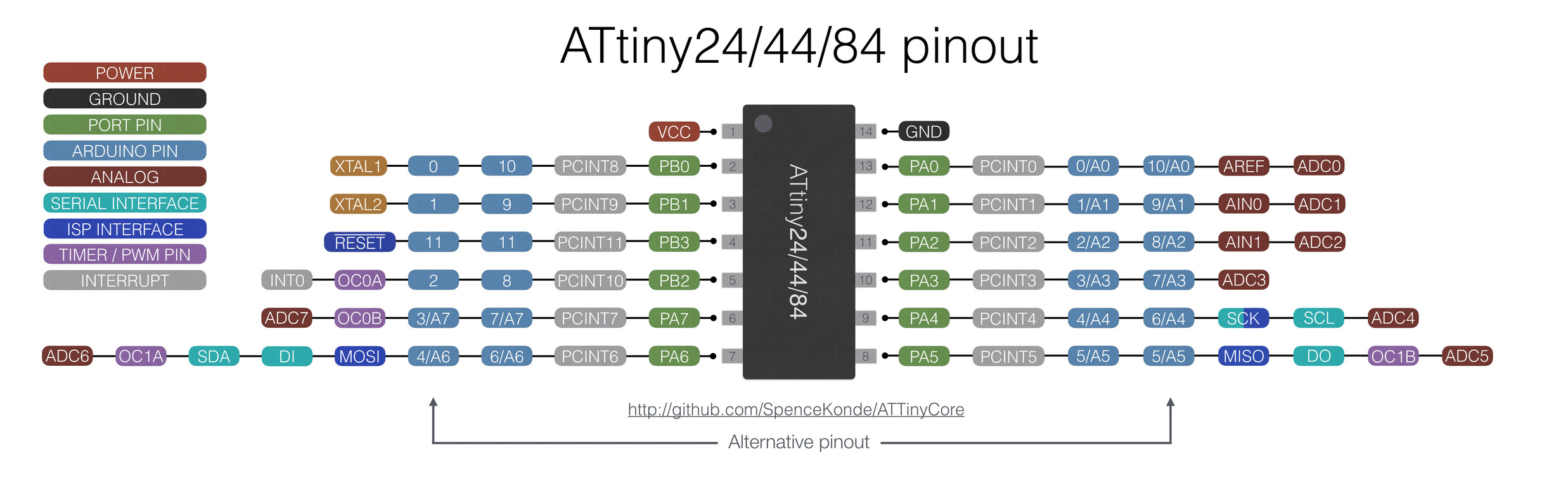
Since I used both an ATtiny44 and an ATtiny45, I will make a comparison here between the two of them reading the datasheet (it is a short comparison since they are pretty similar):
First of all, the ATtiny44 has got 14 pins while the ATtiny 45 has 8. This means that the ATtiny45 is more limiting when doing a project with many components. This is why I chose an ATtiny44 for this second board, since I wanted to connect more components in comparison to the previous one. They both have PWM pins: ATtiny45 has 4 PWM pins and ATTINY44 has 4, too.
All-in-1-board
I designed a board with an ATtiny44 in order to do as much electronic assignments as I could so I put in the board. You can find the documentation in Electronic design
For this assignment I my goal is to program the board to rotate the servo.
🐏 Program
In order to program the board, I opened Arduino IDE.
I then proceeded in create this code to make a servo move. I defined the delay time as an int variable and the pin for the Servo as servoPin.
int d = 100; //delay time
int servoPin =  8; //pin PB2
I then attached the servo to the pin with pinMode in the setup
void setup() {
  pinMode(servoPin, OUTPUT);
}
And in the loop I made the servo sweep with analogWrite.
void loop() {
  analogWrite(servoPin, 10);
  delay(1000);
  analogWrite(servoPin, 250);
  delay(1000);
}
here is the full code.
int d = 100; //delay time
int servoPin =  8; //pin PB2

void setup() {
  pinMode(servoPin, OUTPUT);
}

void loop() {
  analogWrite(servoPin, 10);
  delay(d);
  analogWrite(servoPin, 250);
  delay(d);
}
I compiled this code with COMMAND + R to see if there was any error in the code.
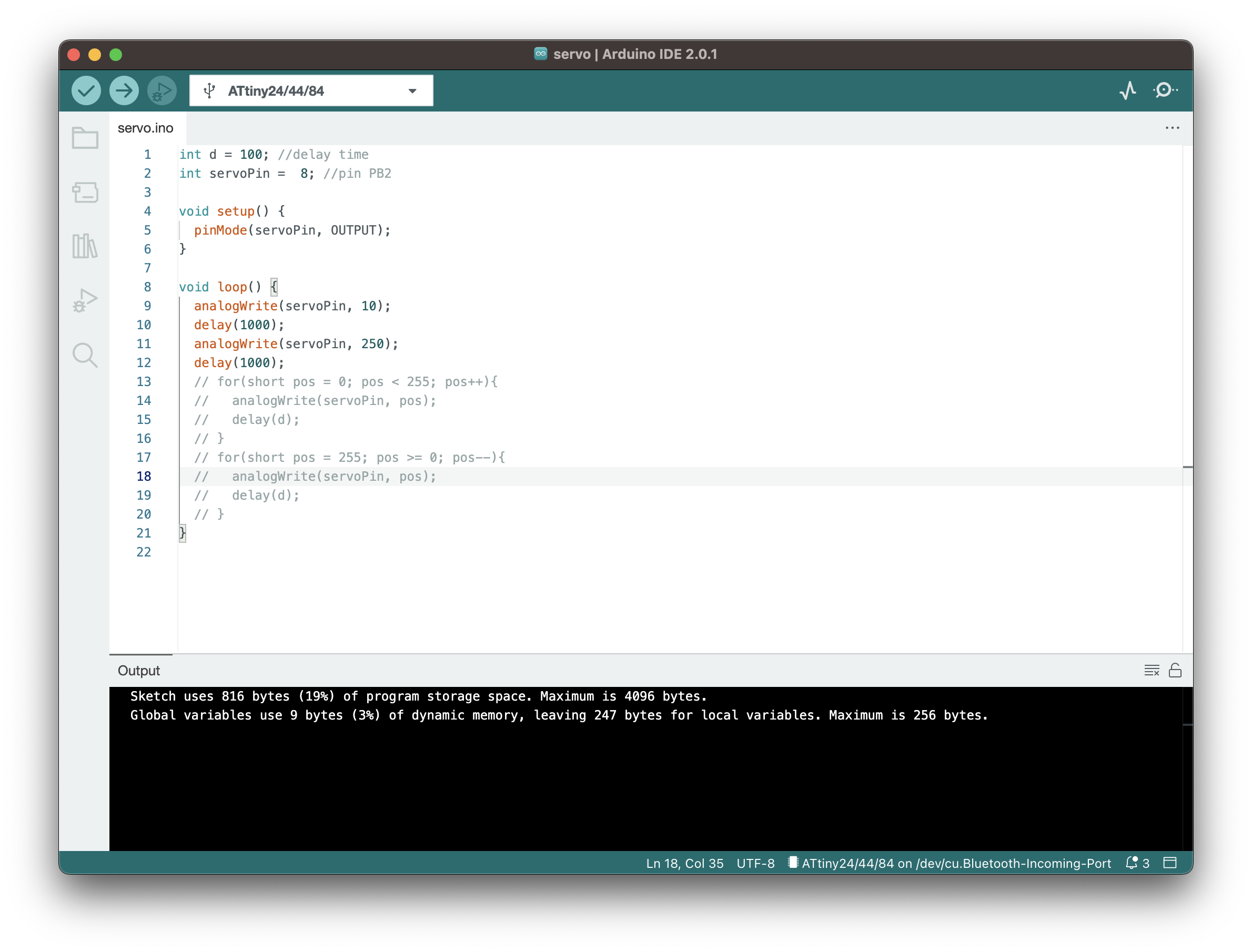
Since everything was fine ( in the Output there is written
Sketch uses 816 bytes (19%) of program storage space. Maximum is 4096 bytes. Global variables use 9 bytes (3%) of dynamic memory, leaving 247 bytes for local variables. Maximum is 256 bytes. )
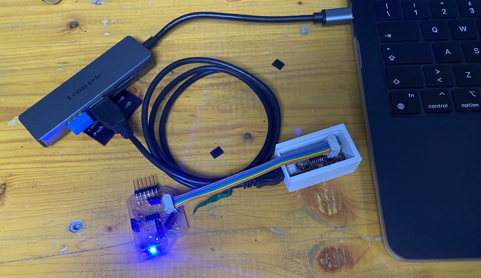
The board, in the meantime, was connected to a programmer:
I proceeded to upload the program to the board. To do so, I did the following steps:
- Select the port
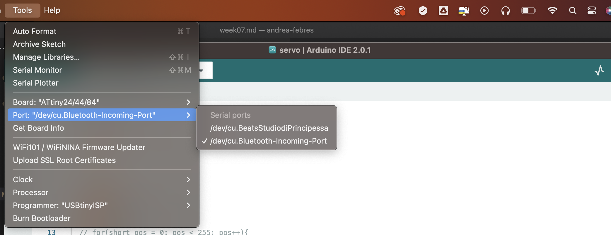
- Select the clock (the attiny44 has 8MHz)
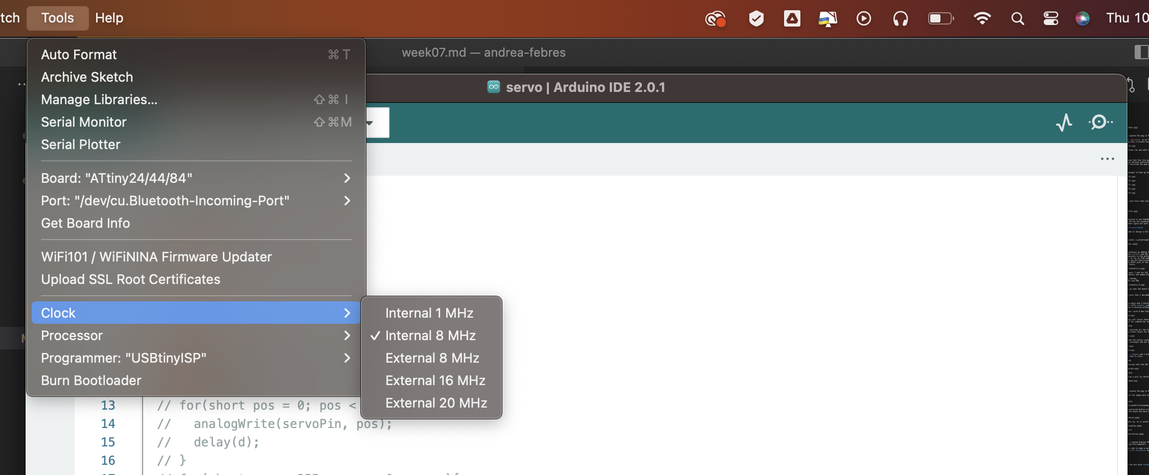
- Choose the processor (ATtiny44)
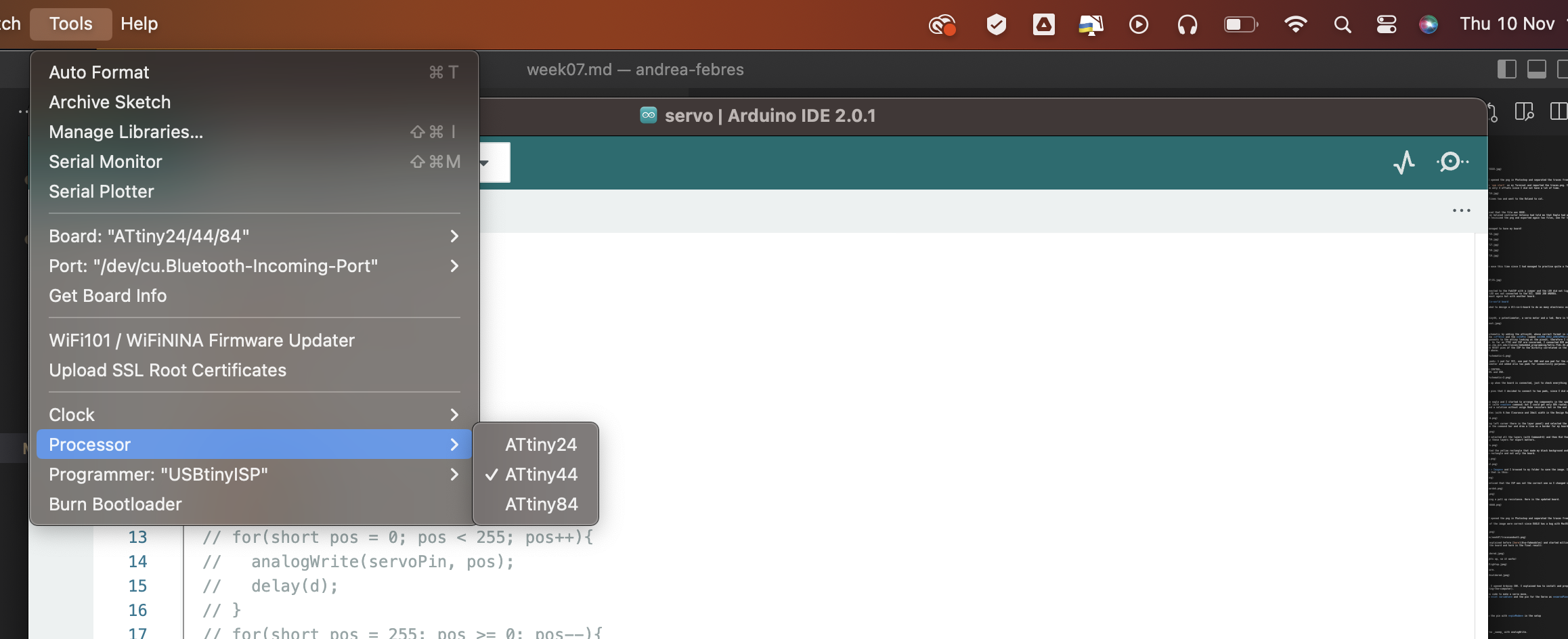
- Choose the programmer (USBtinyISP)
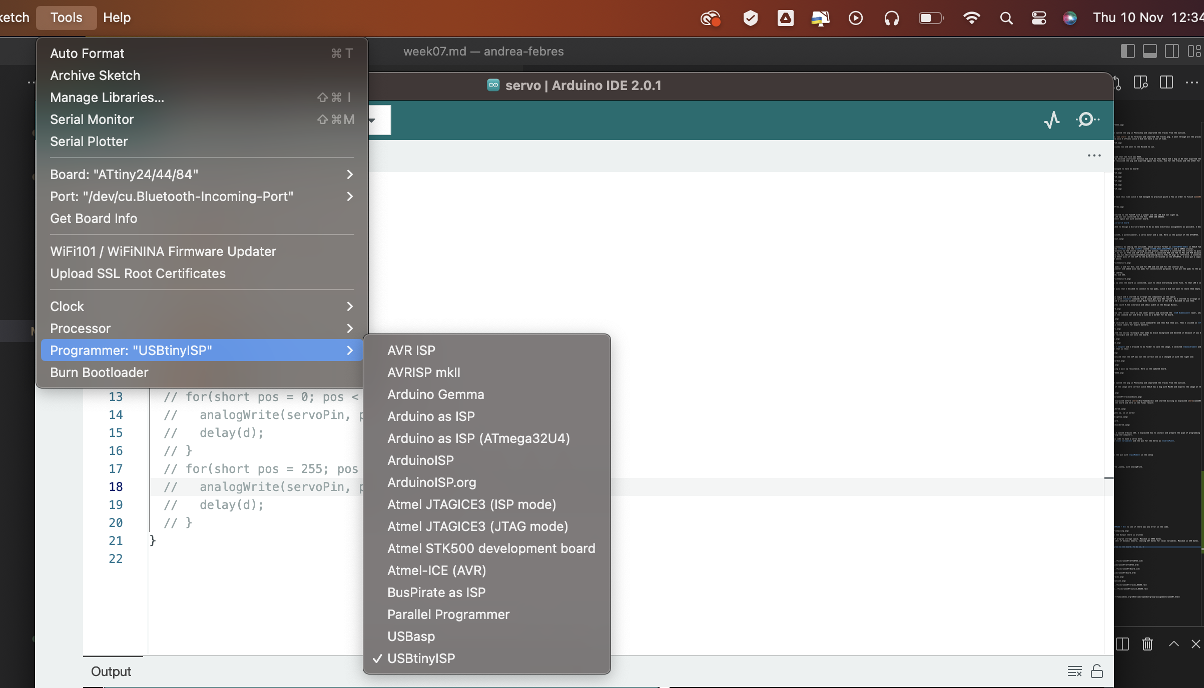
Once I did this, I uploaded the program using a programmer. This is important because if you upload directly it won’t work. To upload using a programmer you can both do Sketch > Upload using a Programmer or do Command + SHIFT + U.
Done this, the servo started to move.