5. Electronics production
- Make an in-circuit programmer that includes a microcontroller by milling and stuffing the PCB, test it to verify that it works.
🌎 A whole new world
Before this week, my knowledge in electronics was equal to zero. After this week is not that high, but a little more than zero. First off, our wonderful instructor Antonio showed us the milling machine. We started off with the Roland MDX40 but the computer was missing. We switched to the ShopBot and first off we took a PCB and taped to the plane of the CNC machine. This step is important to fix the PCB WELL on the board in order to have a more precise mill.
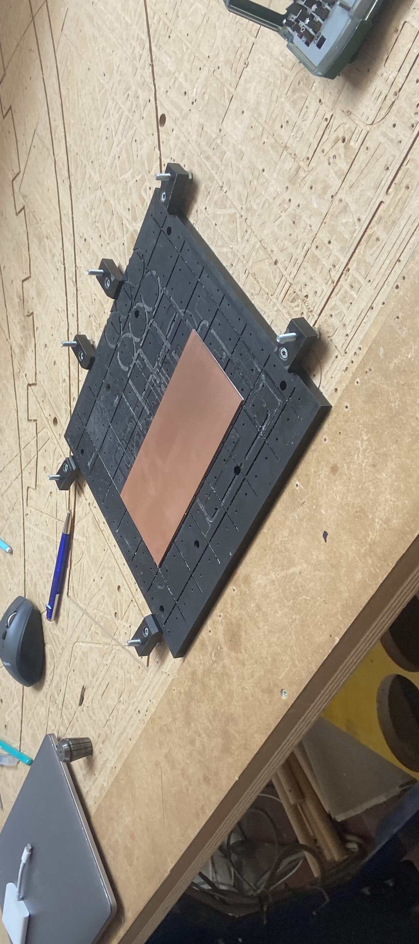
Then we set the x and y origin as well as the z.
We proceeded in doing out group assignment.
🧤 Ali Board
For this assignment, I started off deciding that I wanted to produce the Ali board design I found on the Fab Academy page. It uses the ATtiny44 microprocessor and seemed one of the easiest to weld.
I downloaded the png of the traces and the outline.
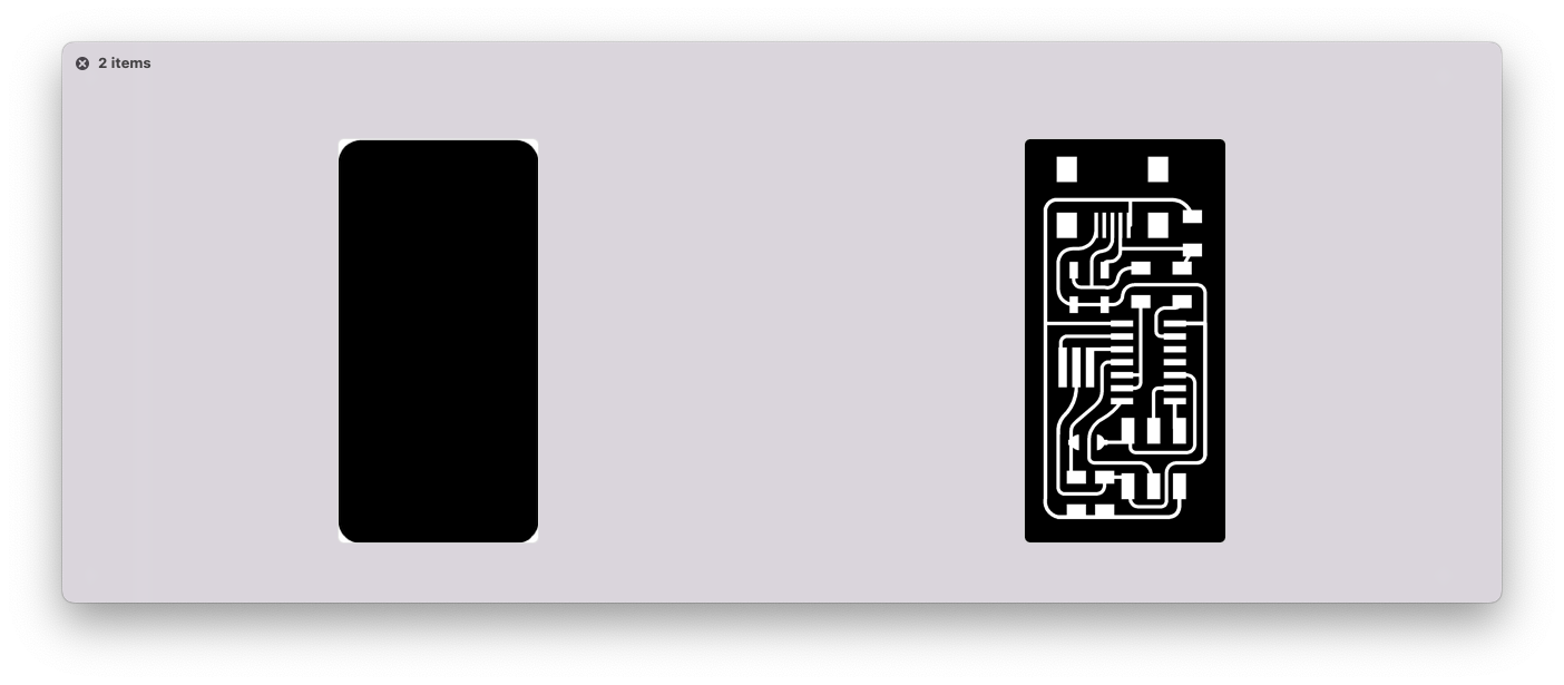
A pcb board to be produced needs these two files, indeed: the first one, traces, has the circuit in it while the outline has the perimeter of the board. The two file must be separated because you need two tips to proceed in the milling.
In order to tell the milling machine the path to follow, you can choose different CAM systems. We were proposed to use either FabModules, Mods or ModsCE. These are all open source CAM systems and before chosing one, I tried MODSCE and FabModules.
👾 ModsSCE
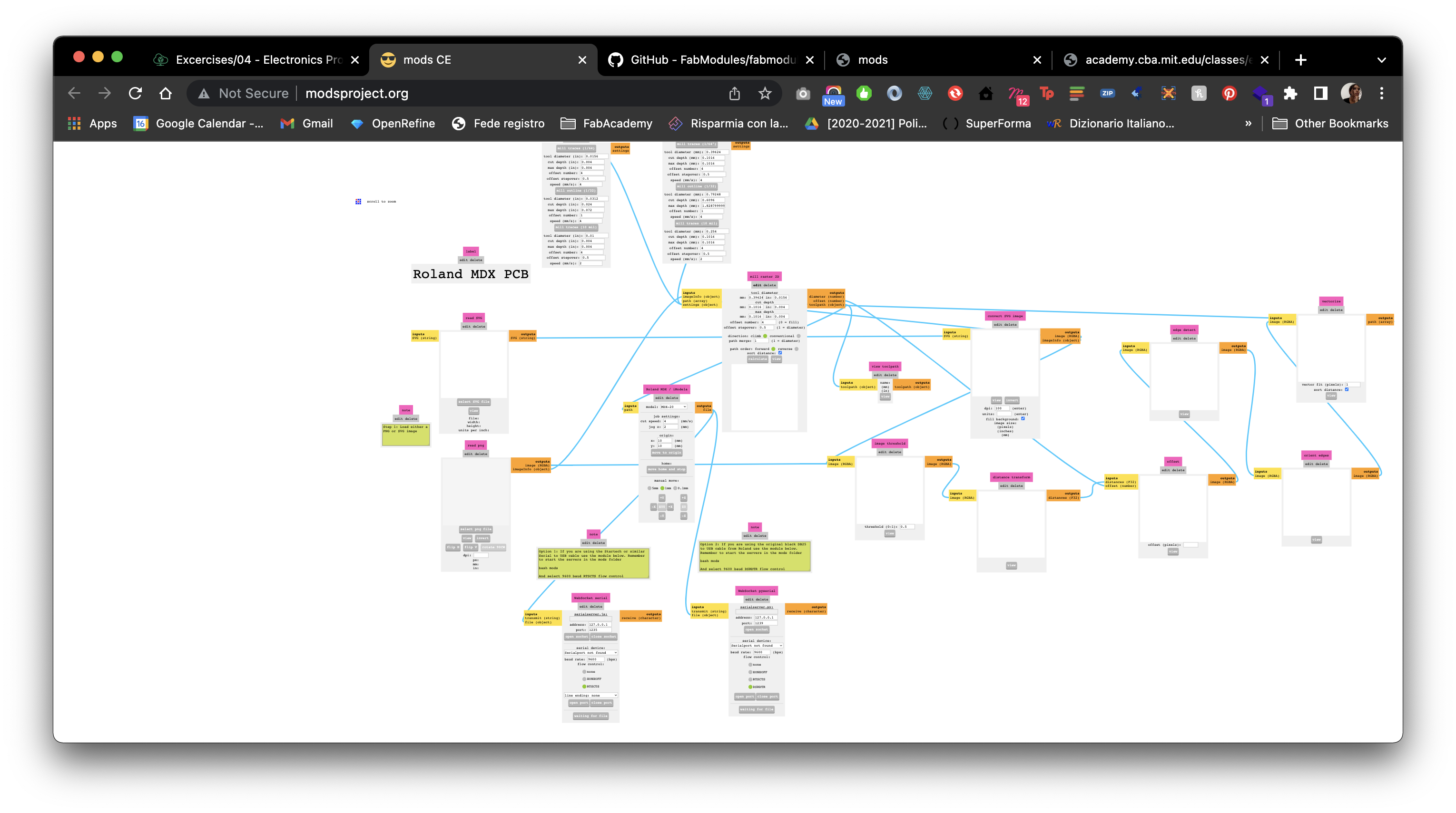
I started off with ModsCE because it was the most colorful, to be honest. To open ModsCE you have to go to the webpage and you will find this interface:
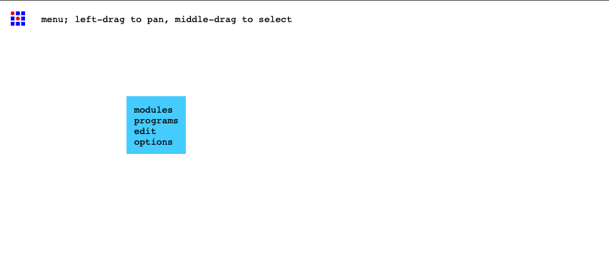
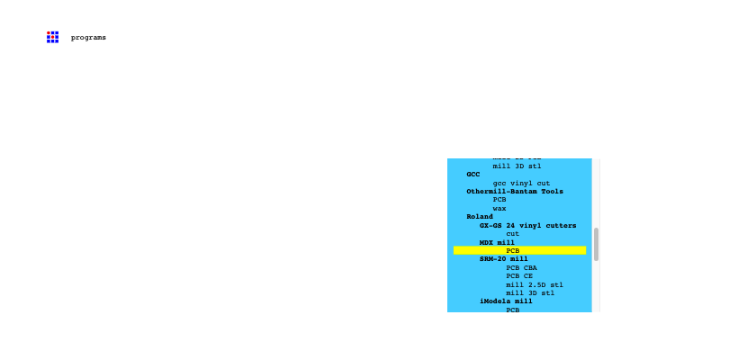
and if you right click the blue rectangle (the menu) appears as shown above. I clicked on open program and I looked for the Roland MDX mill > PCB.
I uploaded the traces png image in the section read png
and then I went to the module for the mill raster 2D where I set the offset number and then I clicked on calculate.
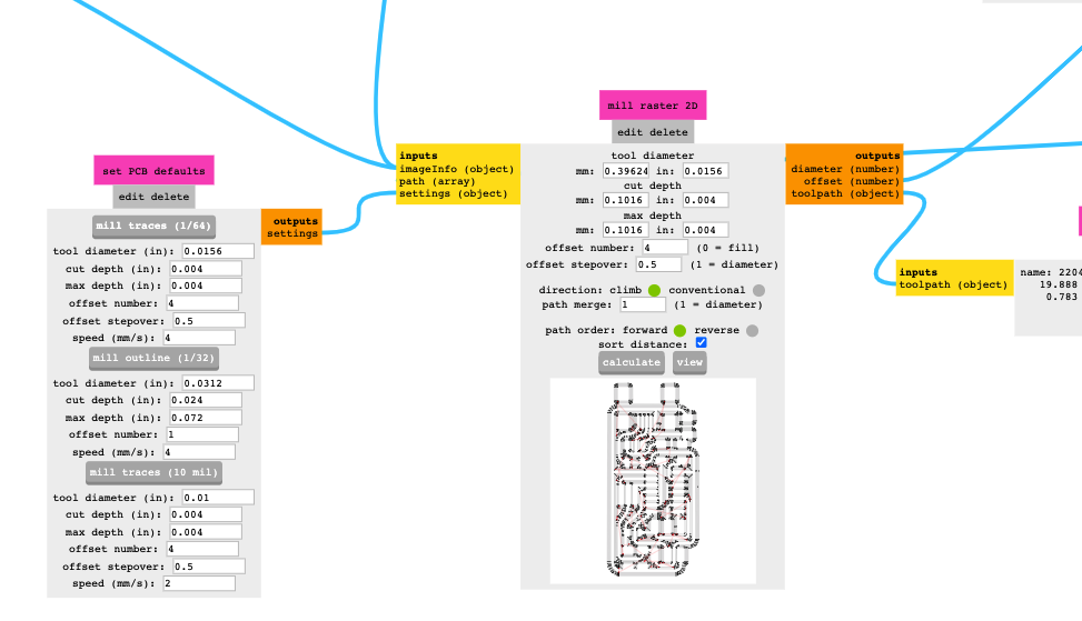
As soon as modsCE calculated, another tap opened with the traces preview. I checked that the traces were not touching one another and went back to modsCE. I then went to the module Roland MDX and selected the correct model, the MDX-40.
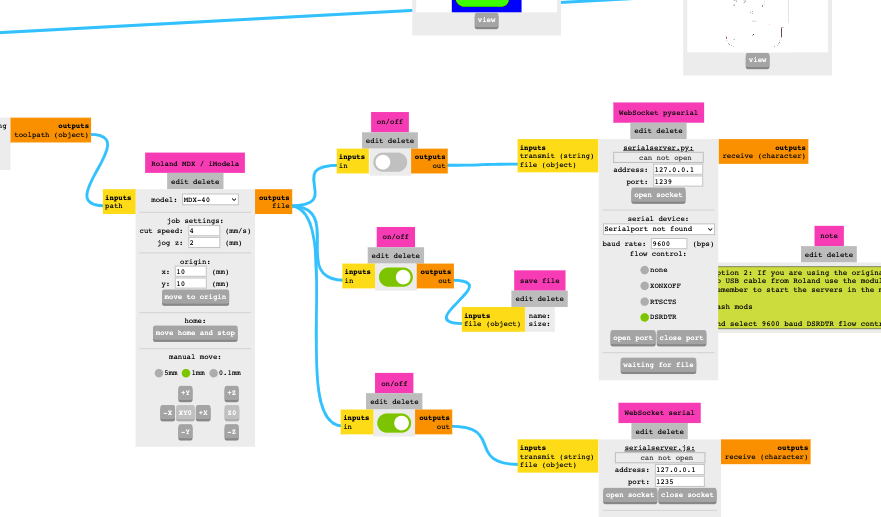
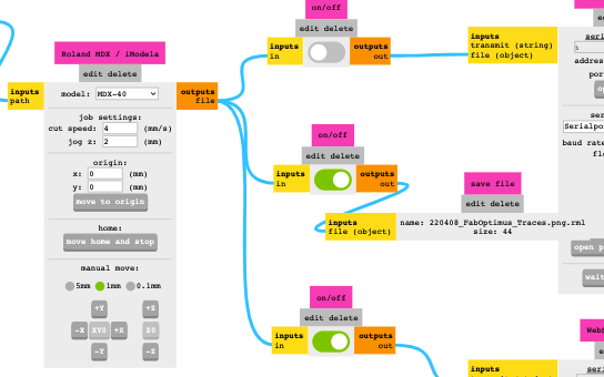
I set the origin X and Y to be 0 so that the origin I set with the machine is the same as the milling file and then I switched on the module connected between roland MDX and save file. Doing so, the file will be saved in my computer as you can see in this screenshot.
👾 FabModules
Then I had to launch FabModules. FabModules is a browser-based CAM system, which allows to generate toolpaths for and control lasercutters, CNC-mills and waterjets commonly found in fablabs. To do so I followed the instructions on the Github page as it follows:
👇🏽 Installing FabModules
I opened the terminal in my computer and I cloned the repository using this code:
git clone https://github.com/FabModules/fabmodules-html5.git
Then I installed the node dependecies:
npm install
🤌🏽 Using
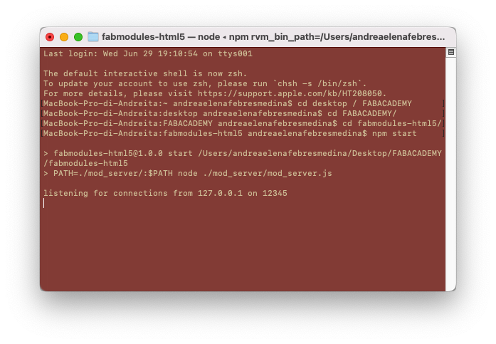
Once FabModules is installed, I started the server usign the terminal. I opened in the terminal the folder of the repository and then I used this code:
npm start
and I opened the web interface with the localhost http://localhost:12345/index.html.
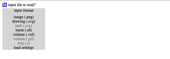
Once the web interface is opened, you can upload the traces image. In FabModules, indeed, the first step is called input format. Among the formats, you can choose the image (.png) one which is the one you need for uploading traces and outline png.
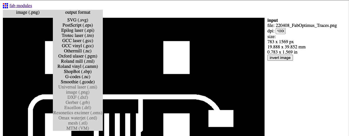
Once the image is uploaded (the traces one), another sections appears, which is the output format where you can choose the machine you will use. In my case, we have both a ShopBot and a Roland mill, as said previously. While we had to start with the ShopBot, when I milled the first pcb board the missing computer of the Roland was found so I chose Roland mill (.rml) in the dropdown list.
At this point, the third section appears, which is the process, where you can choose if you want to proceed with PCB traces or PCB outline. I chose the traces 1/64 and then on the right part of the interface, under output I chose the machine MDX-40.
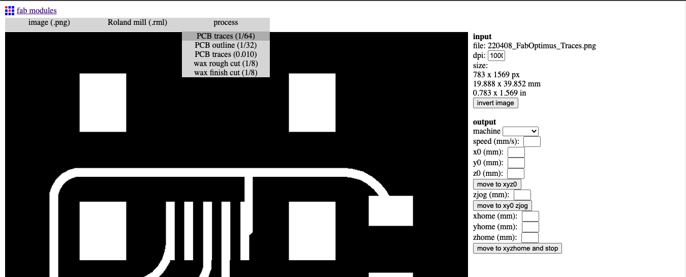
I set the x0 and the y0 at 0 and not at 10mm as it was because I want the origin to be the one I set with the machine.
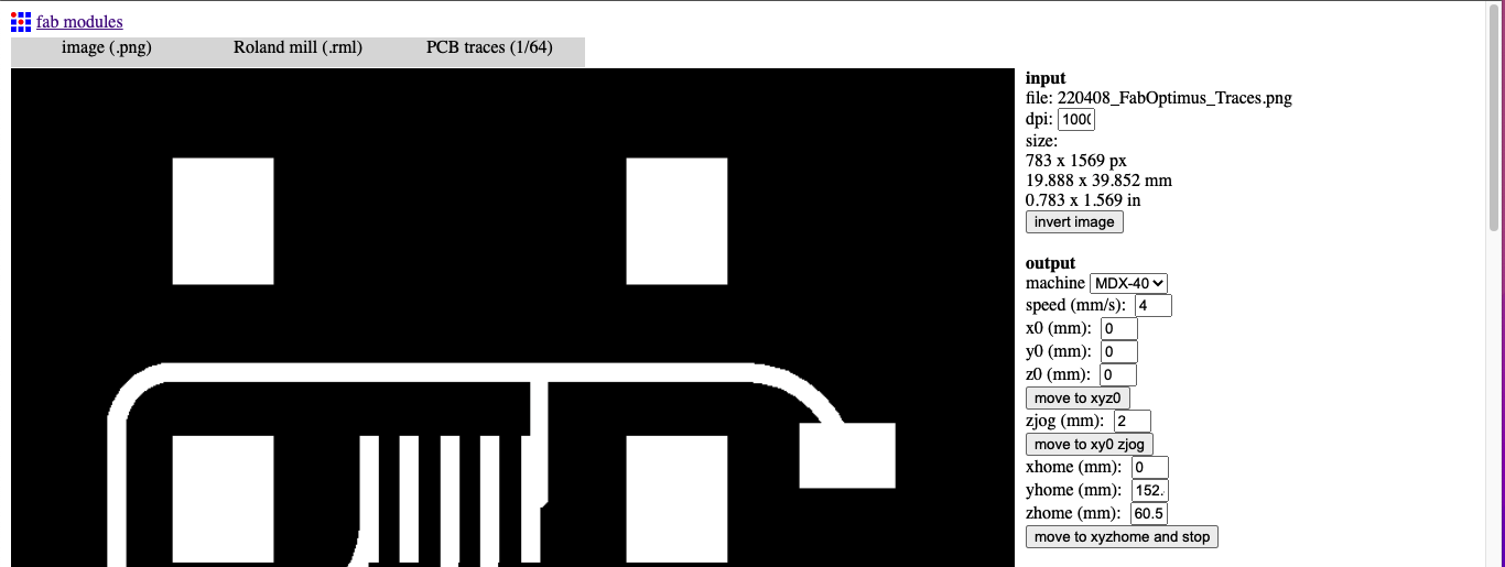
In the process section I set the number of offsets to be 7, which means that the mill will pass 7 times in offsetted lines to clean the traces part. If you want the PCB to be completely clean, you have to set the value to -1. The tool diameter is set at 0.4 mm. After setting these parameters, I clicked on calculate and waited for the process to be finished. Then I inspected the result before saving.
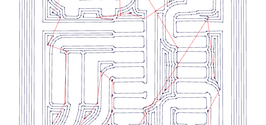
I looked at the blue lines to see if there was any trace that was not properly detached from other traces. In this case, everything was fine.
I saved the file in rml format and started again uploading the outline png in the input section. I chose in the output section the Roland mill and in process I chose PCB outline 1/32.
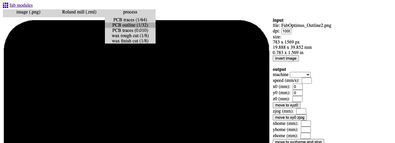
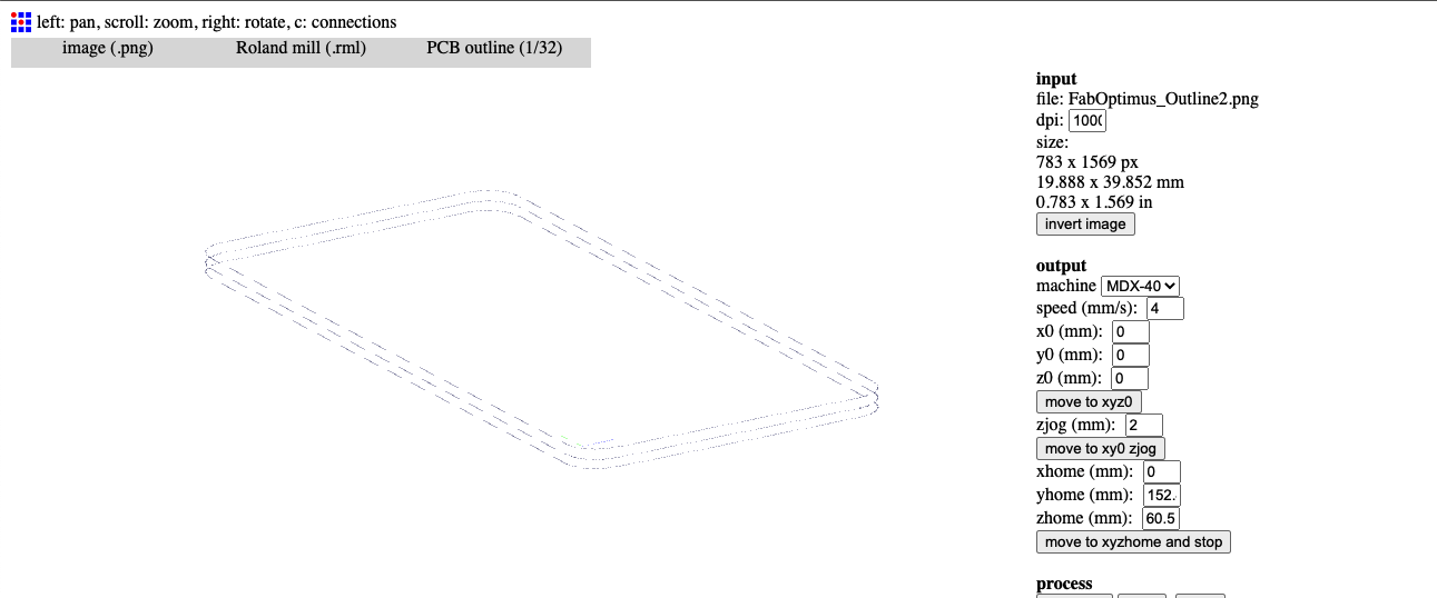
Once I chose again the machine in output, I checked that the origin was 0, 0, 0. This is important because you want the two milling processes to be aligned. In the process section on the right of the page I checked that the cut depth and the stock thickness were correct: you want the cut depth, which is how deep each pass goes, to be proportional to the stock thickness. In this case, the cut depth is 0.6 which means that if I do 3 passes, the pcb will be well cut (0.6*3=1.8mm and the stock is 1.7mm).

I calculated the process and then saved once I checked that there were three cuts.
👩🏽🎤 Milling
Once the files were ready, I transferred them to a USB and went to choose the two drills:
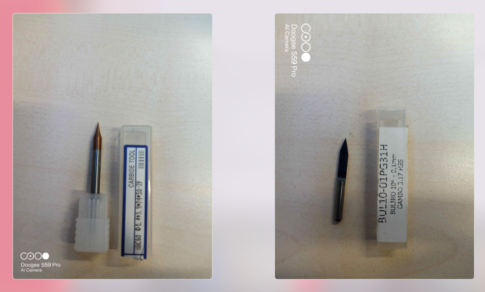
🪡 Mounting the drills
I mounted the drill bit, size 1/64”, for the trace cut. To do so I followed this steps:
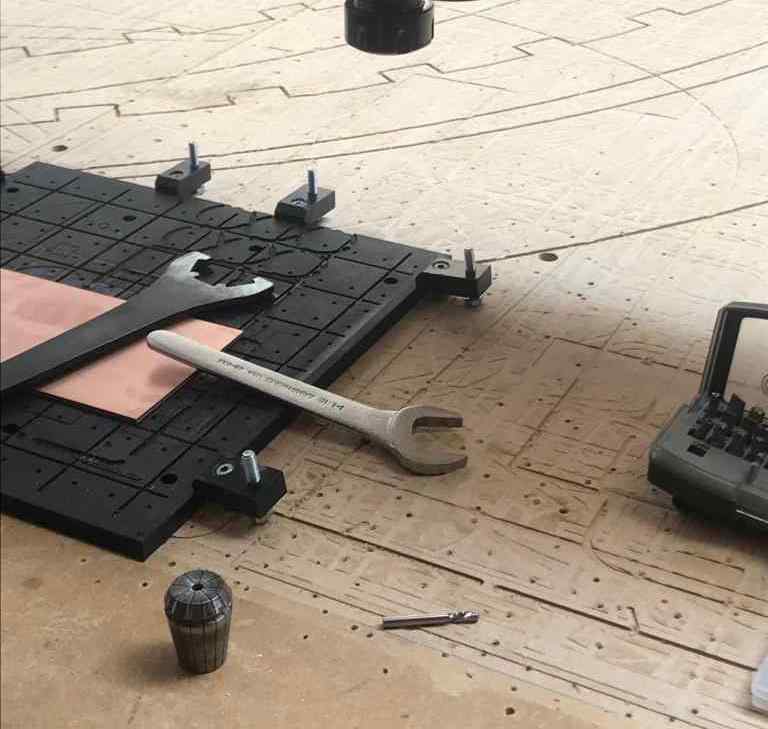
- Adjust the position and the height o the head so you can work in a confortable way (use the Vpanel for this operation)
- Loosen the chuck with the 2 correct wrenches (Remember: to loose the chuck you need to “close” the wrenches, to tighten the chuck you need to “open” the wrenches…mantra of the week!)
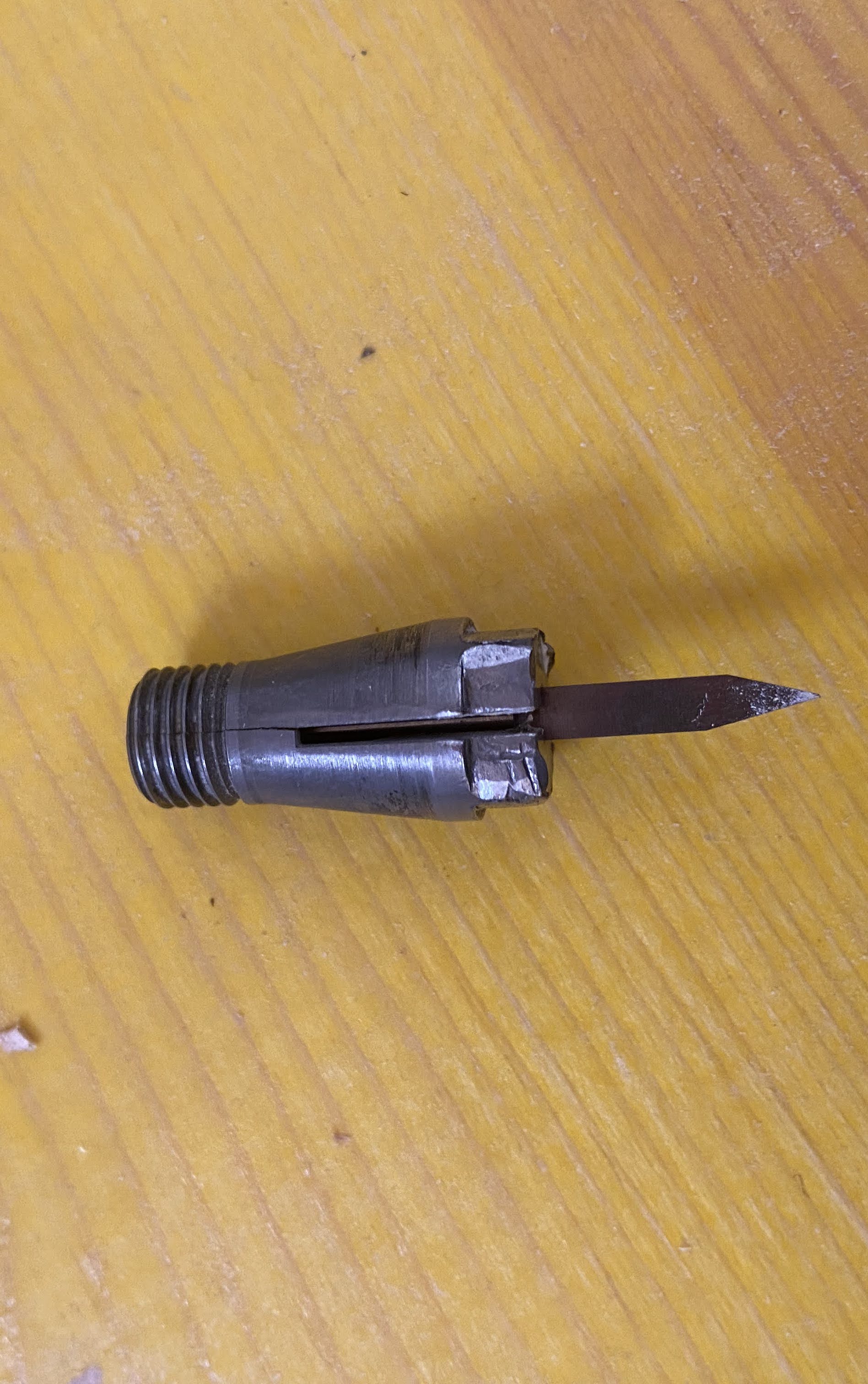
- Choose the correct collect chuck according to the shank size of the endmill
- Fit the collect inside the chuck
- Tighten the chuck (after having put the endmill inside the collect) using the wrenches
🎩 Starting the machine
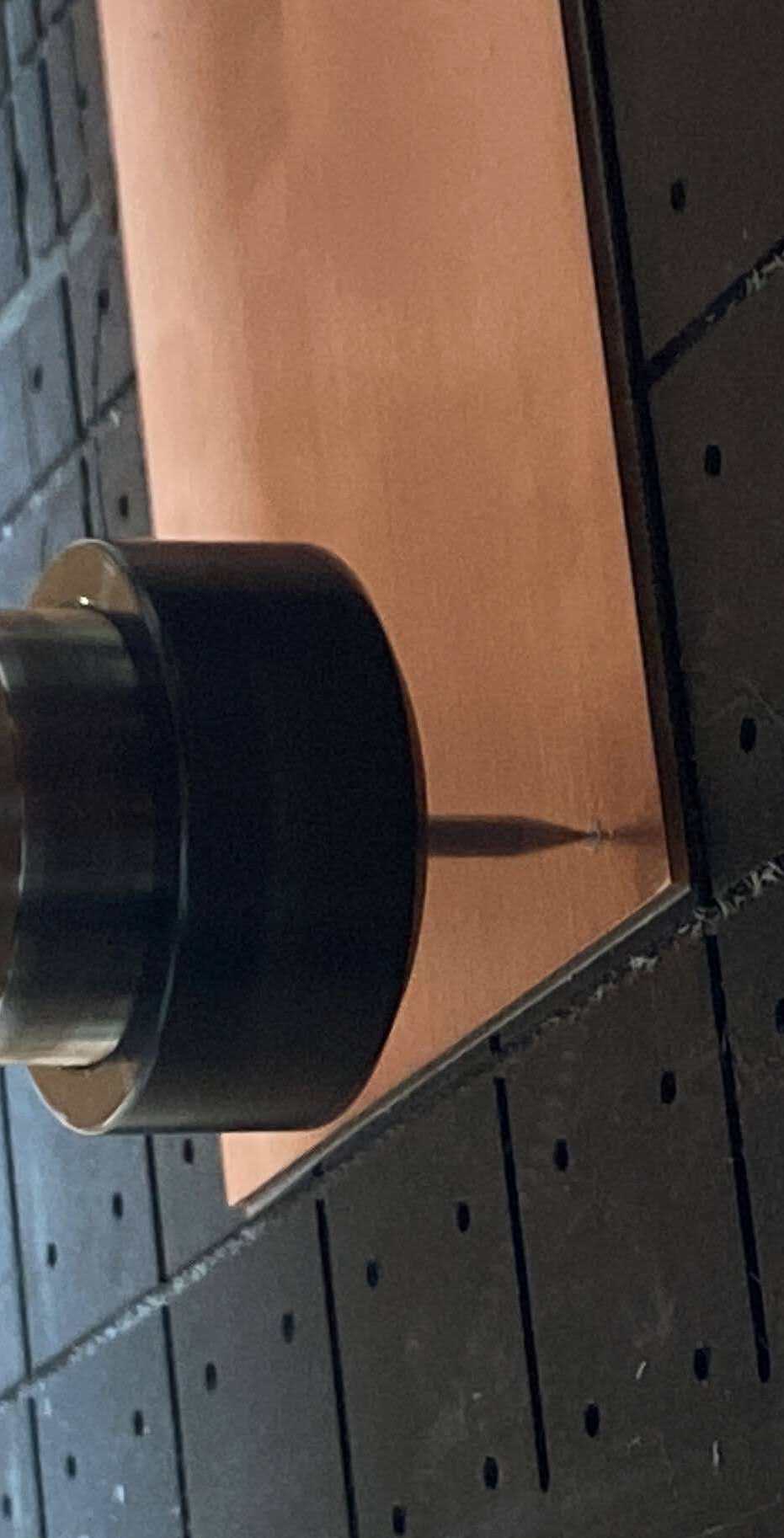
Once the drill is mounted, we open the file in the Roland Cut and we set the origin moving the X and the Y with the interface. Our milling file starts from bottom left angle so I set the origin there. After that I had to set the origin for the Z. Our fabulous instructor Antonio had built for us a “thing” that made a LED light up when the drill touches the PCB.
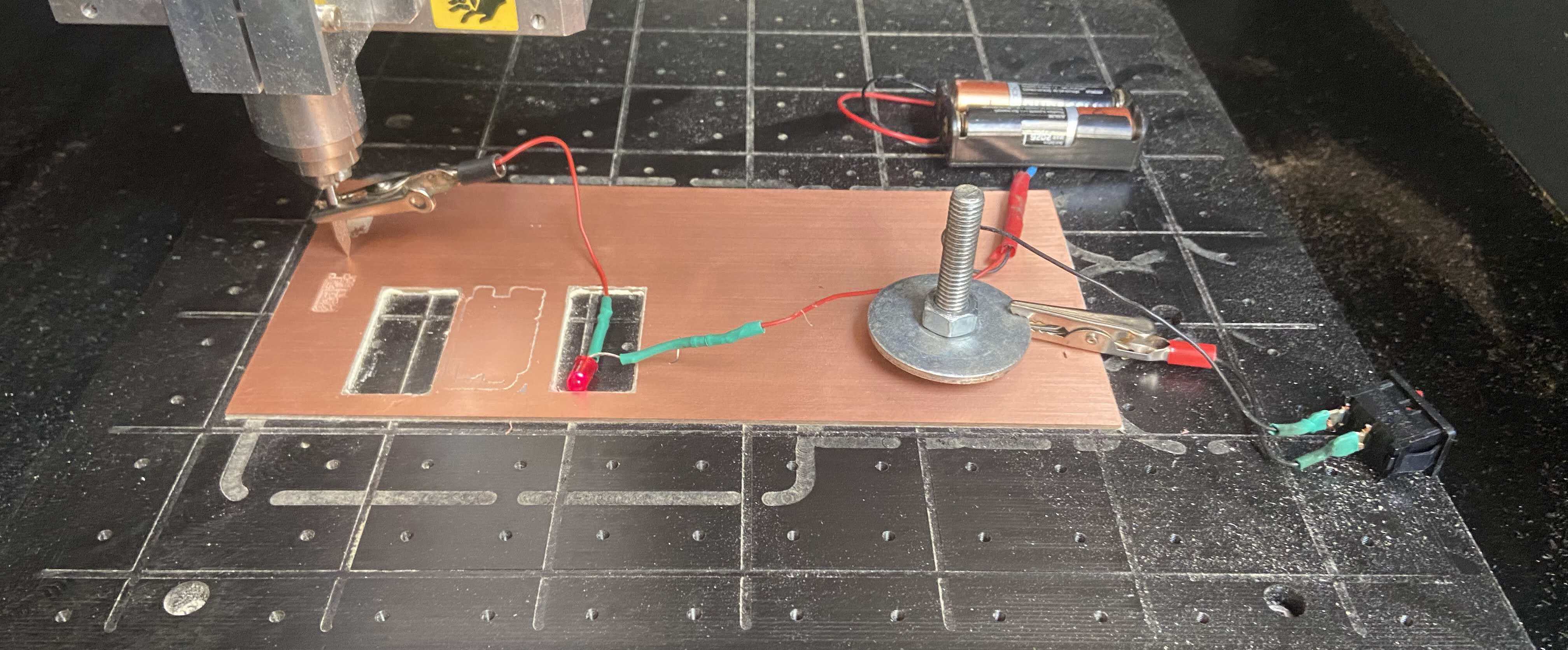
I set the Z origin and then used the Panel to start milling my PCB.
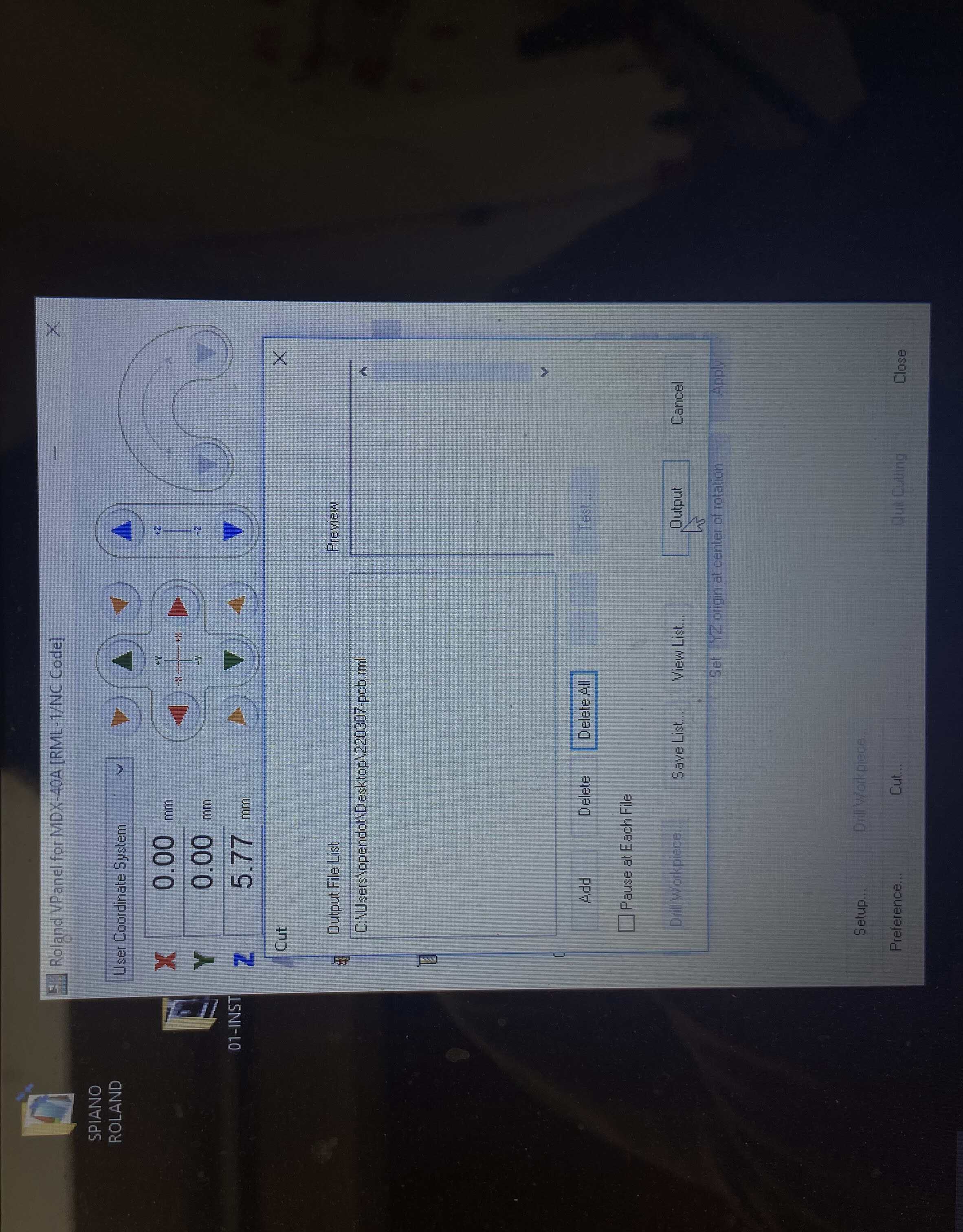
I clicked on cut button and it opened another window where I could upload my traces file. I then clicked on output and waited for the Roland to mill the traces.
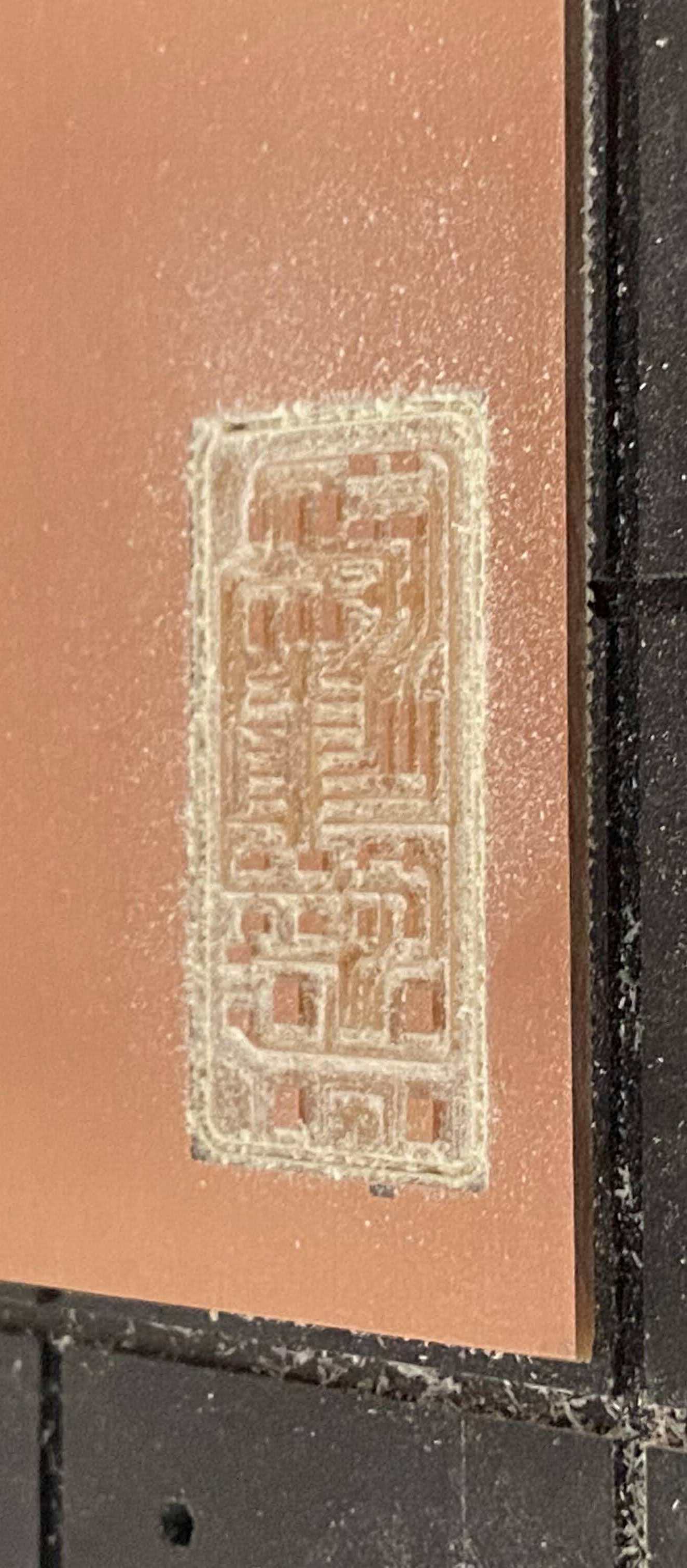
Once the traces were done, I changed the drill to proceed to to the output. Once that was done, too, I detached the PCB and sanded it and then cleaned it with some dish soap. Make it shine baby!
👩🏽🏭 Soldering
With my shiny, cute and wonderful PCB I went to the soldering station. First of all, I searched all the components I needed in the box with all the electronics. It was a tough job since it was the first time I looked at components and I was confused.
Here a list of all the components: * ATtiny44 > Microcontroller
-
3x2 AVR ISP connector > allows programming and reprogramming of microcontrollers soldered on a target PCB.
-
USB connector
-
20MHz resonator > provides an external clock signal to the microcontroller.
-
1uF capacitor > connected between VCC and GND for noise filtering.
-
10K resistor > pull up resistor for the reset pin.
-
R_pullup > 1.5K pull up resistor on the D- line identifying the USB device as a Low Speed device to the host.
-
3.3V diodes > together with the 100Ω resistors, they form voltage clippers on the D+ and D- lines.
-
0Ω resistor > jumper that controls whether the board can be reprogrammed by another device.
I had everything in place and I started soldering the microcontroller, an ATtiny44. Soldering is not an easy task. You have to use a welder and I set the temperature al 300°C. You have to put the welder next to the tin wire and a ball will form, eventually. Then you need like 5 hands to do everything properly: one hand for the pcb, one for the welder, one for the tin wire, one for the component and one to dabb the sweat off your forehead.
Once the ATtiny44 was soldered, I continued with the other components. What I found the most hard to solder was the Cristal, which I still hate profoundly. However, I can say that soldering is just a matter of practise. I discovered overtime which technique was best for me: I find easier to solder components usign a little ball of tin on the trace, than putting the pin of the component on top of the trace and letting the heat of the welder sold everything.
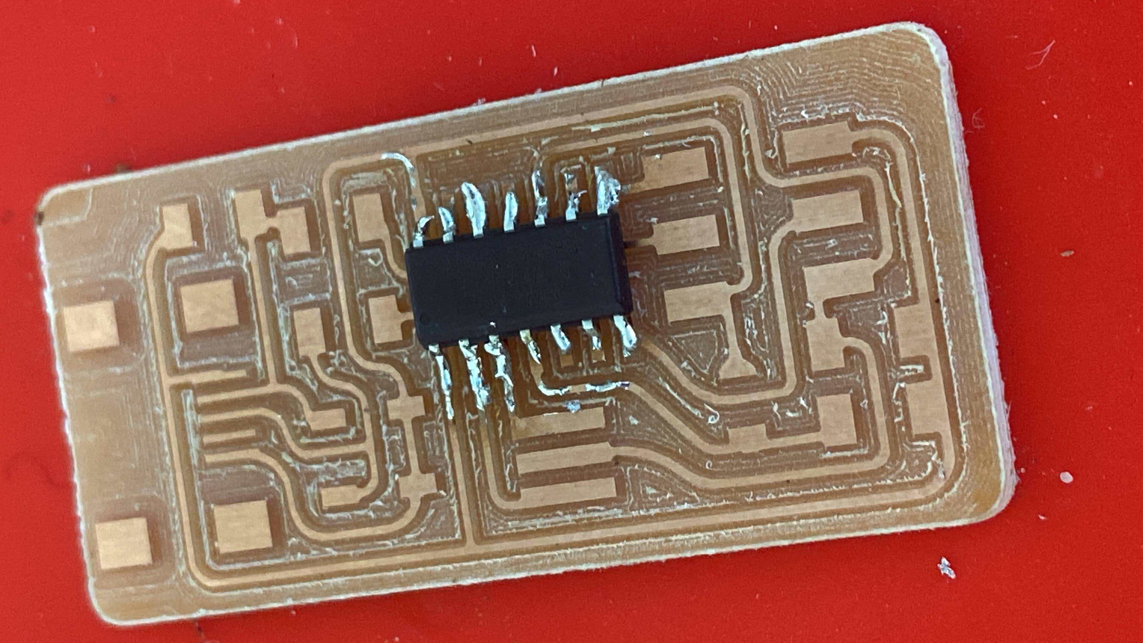
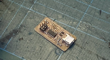
This is the result of the first PCB I soldered and it is really bad.

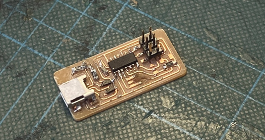
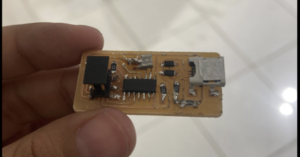
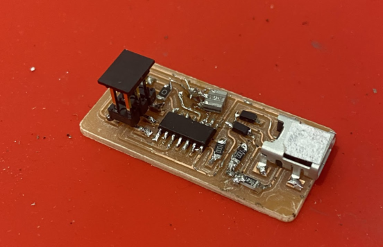
Indeed, I milled and soldered 3 Ali boards during my FabAcademy journey. So fun, uh? Indeed, only one of them turned out to be working fine. Here are the pictures of my other two babies.
- With this one I struggled to solder the crystal, like I could solder it and I burnt the trace.
- This one is all soldered and is the final one.
🥵 Will it function?
It is time now to program the FabISP. In orded to do so, I followed the tutorial you find at this link.
🍀 Installing the necessary
I have a MacBook so I first downloaded and installed Crosspack AVR and then downloaded the firmware (you find all the links and better tutorial at the link linked below).
🤖 Programming time
Antonio gave us another programmer (his programmed FabISP) that was connected with a USB cable to the computer. I connected that programmer to my FabISP with a jumper and I went to the Terminal. I navigated to the directory where I saved the FabISP firmware with the code
cd Desktop/fabISP_mac.0.8.2_firmware
I then started to compile the firmware with this code:
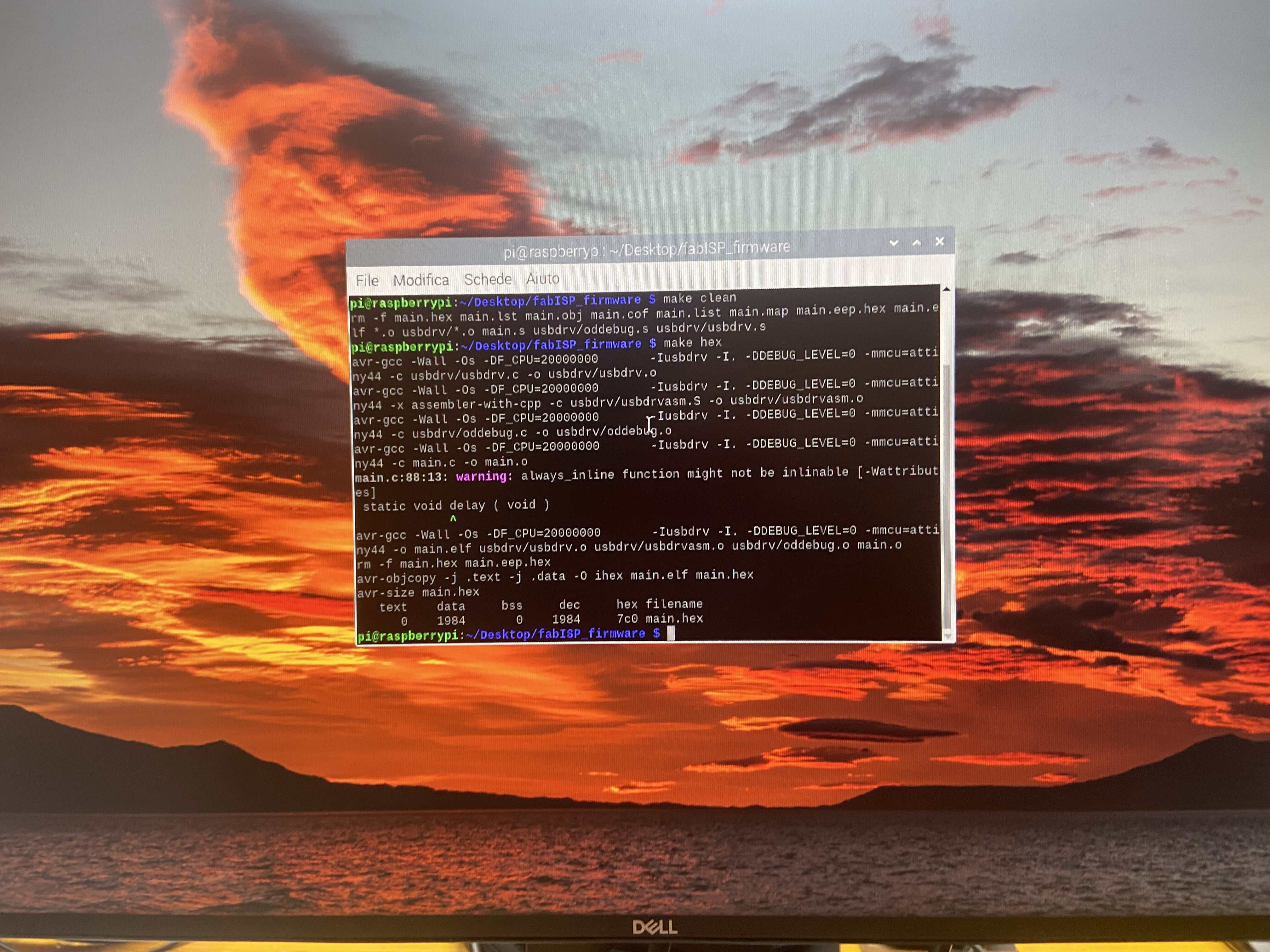
make clean
The code was successfull because I got this code back:
andreaefebresm:~/Desktop/firmware$ make clean
rm -f main.hex main.lst main.obj main.cof main.list main.map main.eep.hex
main.elf *.o usbdrv/*.o main.s usbdrv/oddebug.s usbdrv/usbdrv.s
I went on with make hex and it was a success.
Then I did make fuse and I got an error, the worst error: r=-1.
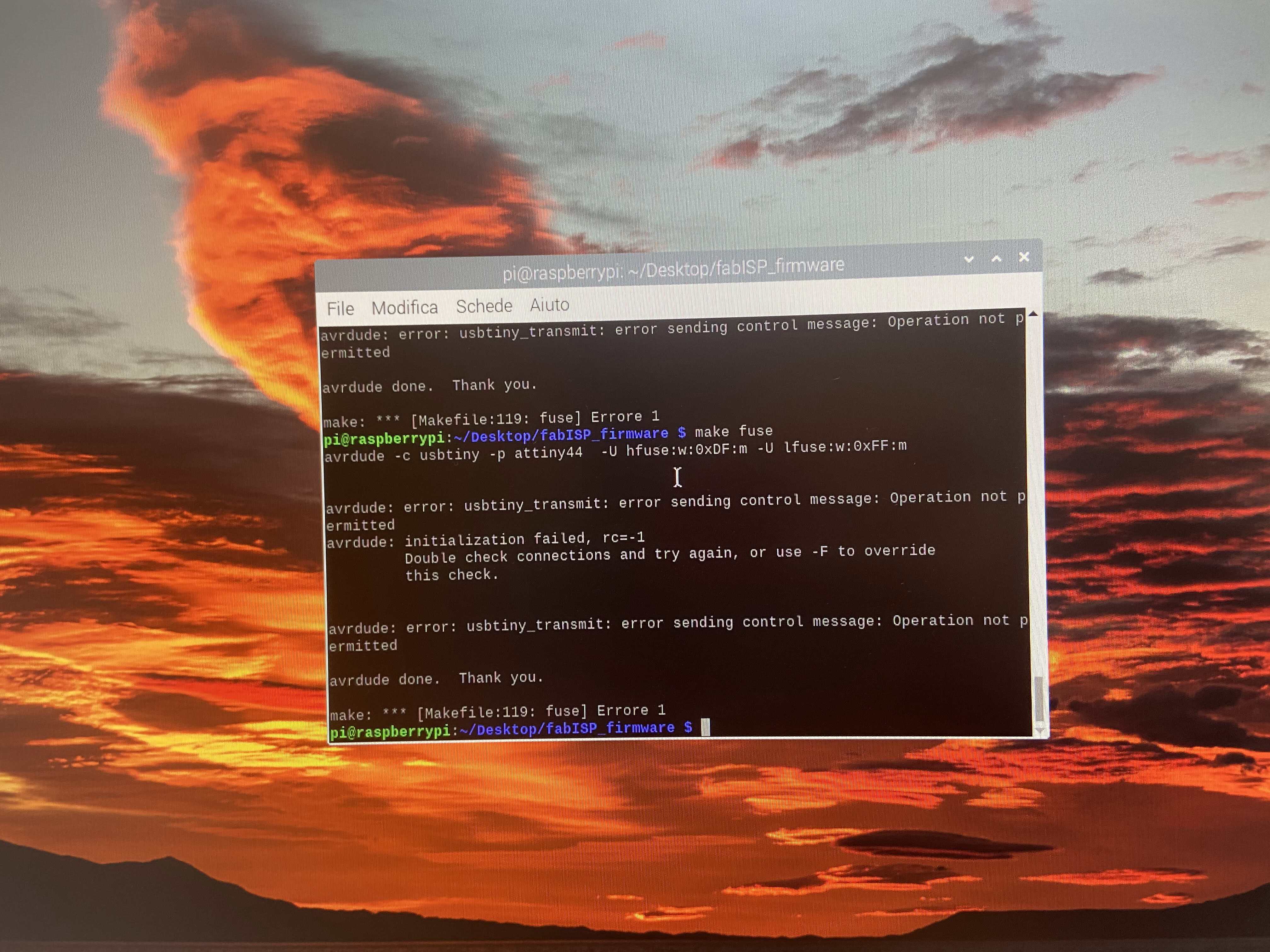
This means that I had some circuit problems which I fixed using a Digital Multimeter and milling and soldering 4 PCBs until I got no error.
Then I did make program and the last time it worked.
After programming it, you have to remove the 0 ohm resistor and cut the jumpers.