
For the group assignment, we had to use our lab equipment to observe the operation of a microcontroller circuit board. In our lab we had a multimeter and a oscilloscope and we used our pcb boards as tests (they really needed to be tested because we are still not so professional in soldering). Before starting, we listened to the explanation of these two instruments.
A multimeter is a measuring instrument that can measure multiple electrical properties. A typical multimeter can measure voltage, resistance, and current, in which case it is also known as a volt-ohm-milliammeter (VOM), as the unit is equipped with voltmeter, ammeter, and ohmmeter functionality.
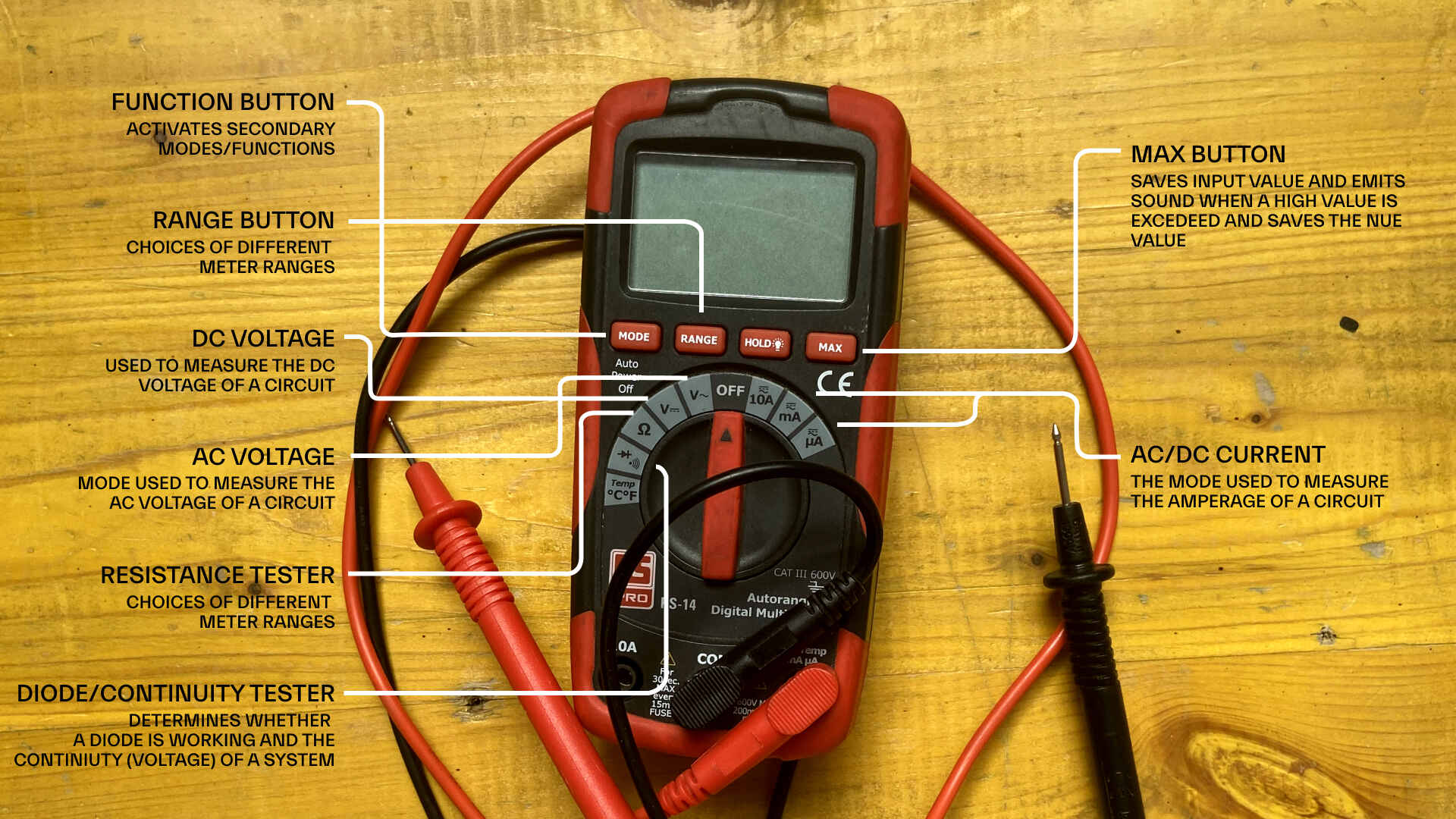
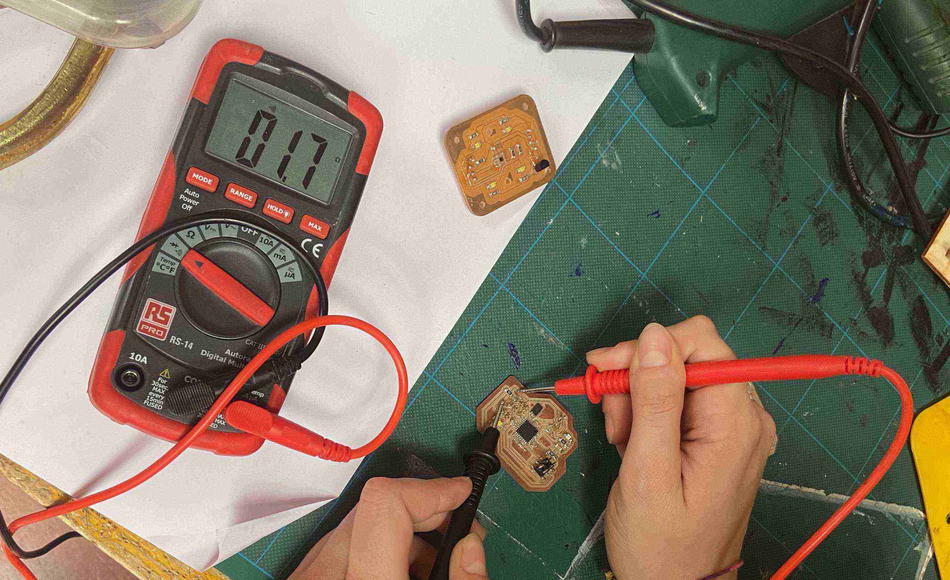
The first thing we did was to put the multimeter in Continuity mode, which is indicated with the symbol similar to a Wi-Fi. After rotating the toggle to reach the symbol, we clicked on MODE to select the correct function: in our multimeter, if we do not do that we select another function which is the diode tester.
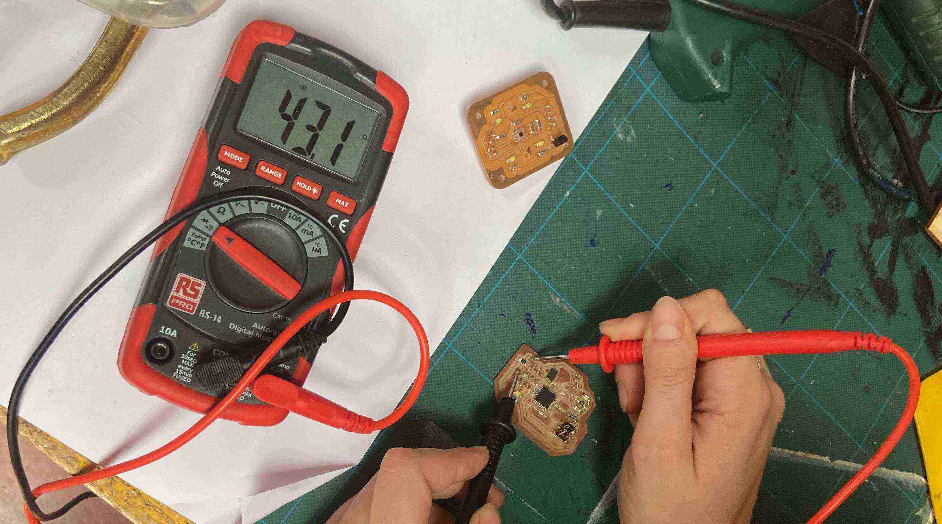
We took our pcb board and we placed the red cable on one ISP pin and the black one on the corresponding trace.
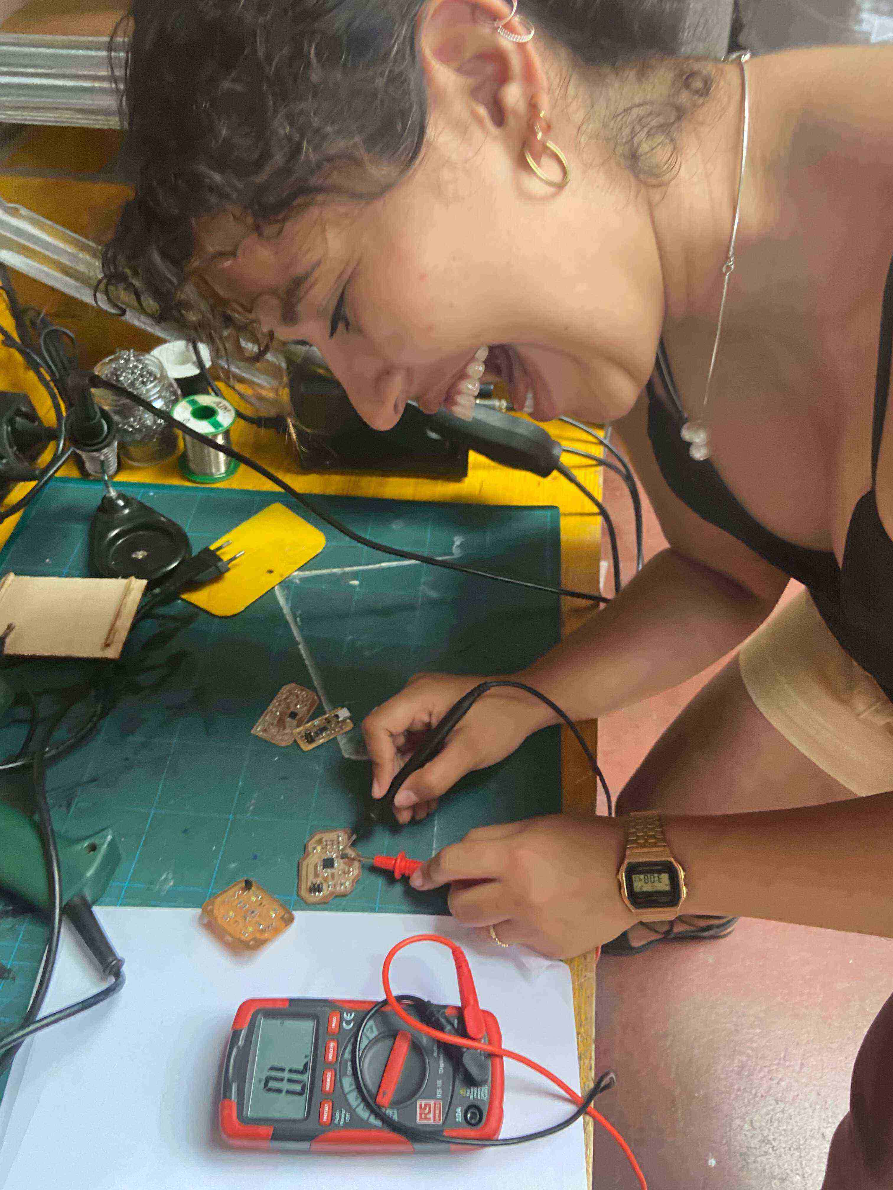
The multimeter made a sound and changed value so we knew that there was continuity between the two.
An oscilloscope is a laboratory instrument commonly used to display and analyze the waveform of electronic signals. In effect, the device draws a graph of the instantaneous signal voltage as a function of time.