Output devices
This week there are two types of assignments, one group and one individual. In my case I’m alone in ESNE’s Fab Lab so I am doing both.
Assignment
Group assignment:
- Measure the power consumption of an output device
Individual assignment:
- Add an output device to a microcontroller board you've designed, and program it to do something
Group assignment
Group assignment page
In the following link you can access the Leon Fab Lab page that contains all the group assignments: Fab Lab Leon group assignment page
Measure the power consumption of an output device
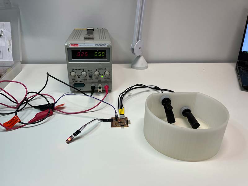
To measure the consumption of a board with an output I chose my level measurement board from my final project. This board has two level sensors as input and a neopixel RGB LED as output.
To measure the consumption of my board, I connected the power supply of my Fab Lab with a voltage of 5V and started to measure the consumption of the board.
The board with the red LED has a consumption of 0.25 A.
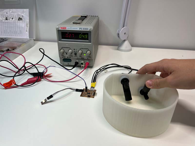
Since I had the board connected, I wanted to measure its consumption by changing the color of the LED to see if the consumption varied. I turned up one of the sensors so the light was yellow. With the yellow light the consumption changed to 0.27 A.
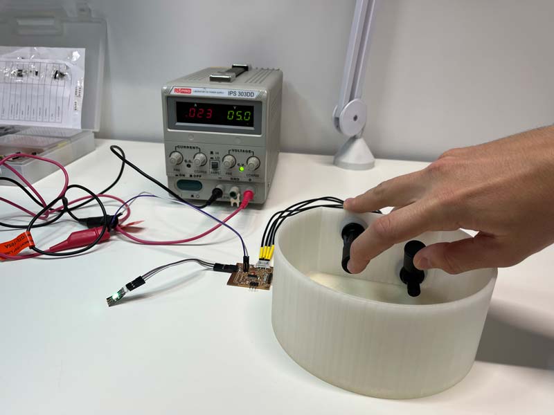
When I changed the color of the LED to green the consumption changed to 0.23 A.
Then I went to measure the milliamps that it consumed with the multimeter. To measure consumption in W, I looked at Adrian Torres’ documentation, where you can see the diagram of how to connect the multimeter to obtain the correct reading. The measurement obtained was: 0,831 A
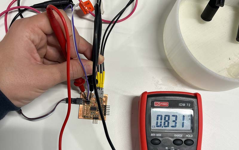
The power source has a voltage of 5 V and we take the consumption greater than 0,831 A.
P = V x I P = 5 x 0,831 = 4,15 W.
Individual assignment
Add an output device to a microcontroller board you’ve designed, and program it to do something
My Outputs board is a board that must take the signal from two level sensors and with that information change the color of an Neopixel LED to red, yellow or green, depending on the water level. The microcontroller I use for my board is an AtTiny 1614 because it has enough memory to store the program I need and the number of pins needed to connect everything my board needs.
THE NEOPIXEL LED
These devices always have GND and VDC or Vin, to power the LEDs and next to them there is a pin labeled DIN (Data In) and DOUT (Data Out).
The idea is that we can cascade Neopixel devices, connecting the output of one to the input of another and passing the power pins through the contacts. In this way, we can make cascades of the size that our power supply allows us (Theoretically) without problems.
The closest pixel to the input is usually number 0 and up from there. Each pixel of our display has a unique and consecutive address. If we connect two 8×8 matrices in cascade, the first matrix will have pixels from 0 to 63 and the first pixel of the second matrix will be 64, etc. In principle, cascaded devices do not have to be the same. That is, I can join an 8x8 matrix to a 16x16 matrix and finally add an 8-pixel ring, provided they all use the same controller chip.
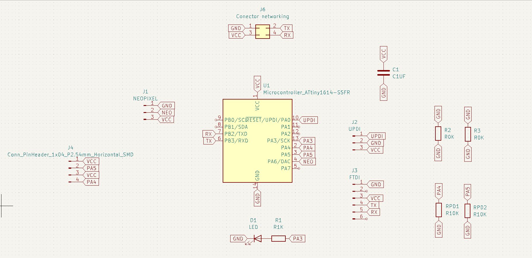
I started by designing the schematic of the board in KiCad, in the following image you can see the connections of each of the elements.
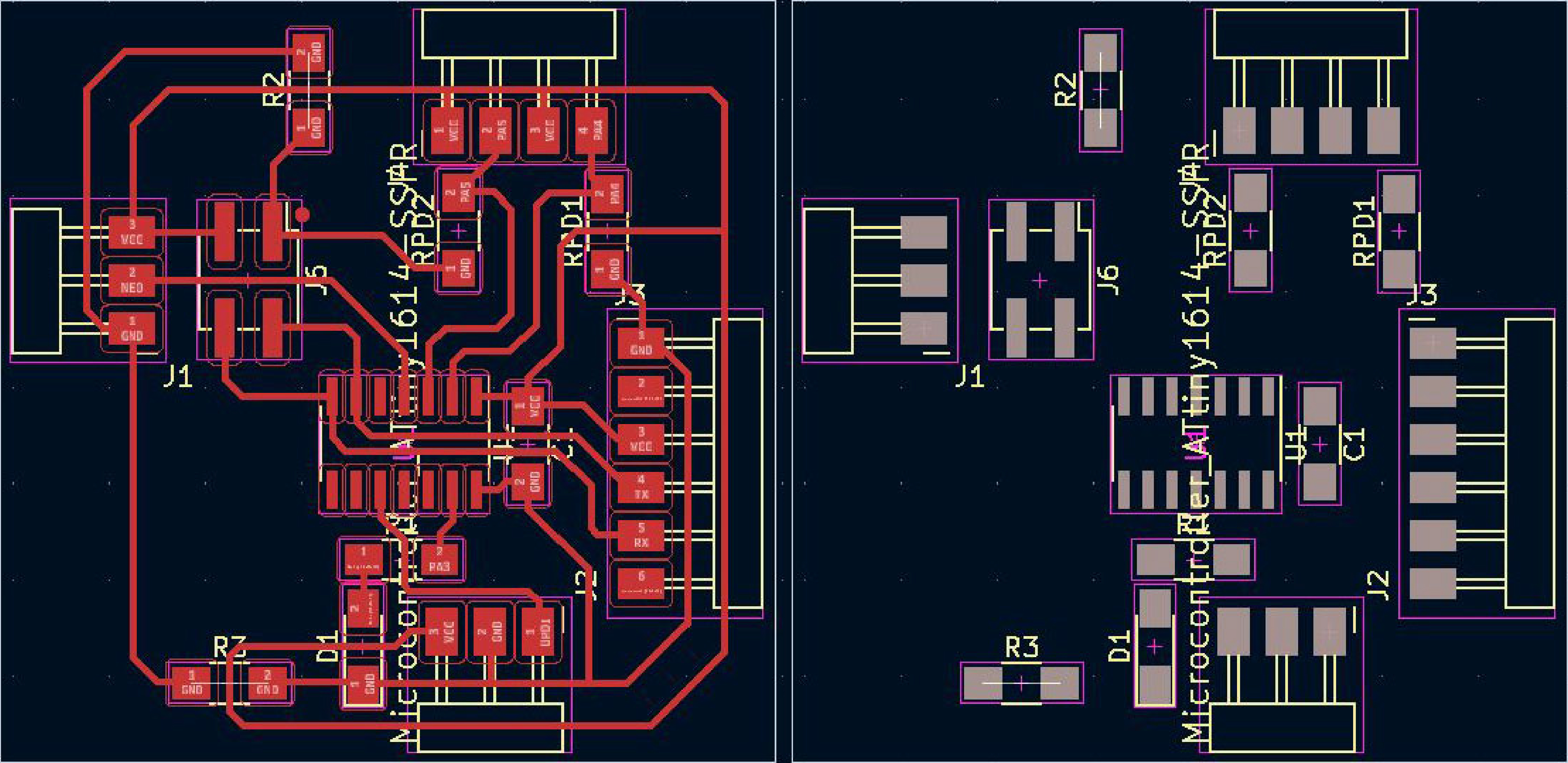
Then I placed the elements on the board and connected them as you can see in the following image.
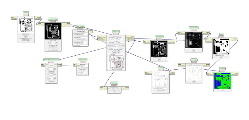
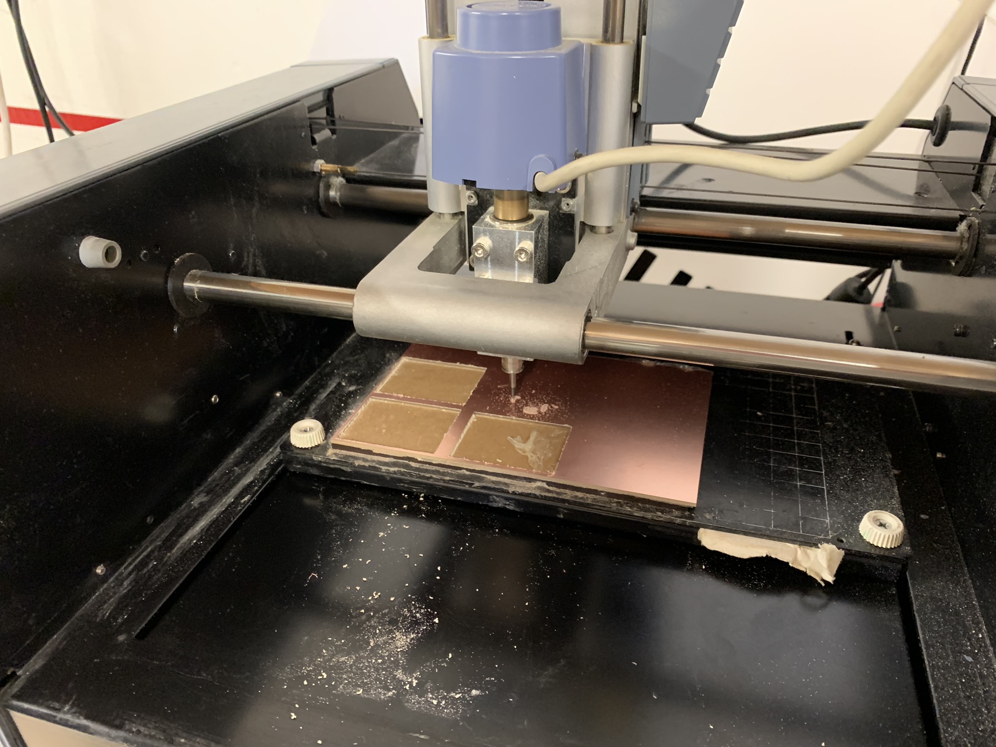
With this design using mods I got my milled board ready to solder the components.
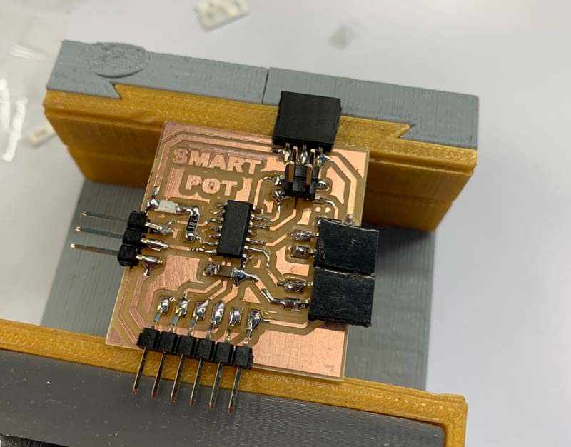
With all the components of my board soldered, I checked the continuity of all the elements to make sure that everything was well soldered. All connections were fine. After checking this I started with the programming of the board in Arduino. Here you can see my program for the board. The color of the LED depends on the status of each of the level sensors.
In order to use this type of LED it is necessary to download and install the Adafruit Neopixel library, you can find it by clicking HERE.
In this link there is also a tutorial on how to install the library correctly. In my case, this library was already inside my Arduino IDE and I only had to select it and install it.
// Code for Hello ATtiny 1614 with 1 leds and 2 level sensor
//By Pablo Pastor Fabacademy 2022

#include <tinyNeoPixel.h>

#define PIN 2 //  Pin de control

// Parameter 1 = number of pixels in strip
// Parameter 2 = Arduino pin number (most are valid)
// Parameter 3 = pixel type
//   NEO_GRB     Pixels are wired for GRB bitstream (most NeoPixel products)
//   NEO_RGB     Pixels are wired for RGB bitstream (v1 FLORA pixels, not v2)
//   NEO_RGBW    Pixels are wired for RGBW bitstream (NeoPixel RGBW products)

tinyNeoPixel strip = tinyNeoPixel(1, PIN, NEO_GRB + NEO_KHZ800);

int abajo;
int arriba;

void setup()
{

Serial.begin (115200);
pinMode (0,INPUT);
pinMode (1,INPUT);
Serial.println ("Hola");

strip.begin();
strip.show(); // Initialize all pixels to 'off'

}


void loop()
{

  abajo = digitalRead(0);
  arriba = digitalRead(1);
  Serial.println ("Arriba");
  Serial.println (arriba);
  Serial.println ("Abajo");
  Serial.println (abajo);

//strip.setPixelColor(0, 200,0,0); //Show red on the first LED (The first LED is the LED 0)(R)(G)(B)
//strip.show();


if (arriba == 0 && abajo==1)
{
  strip.setPixelColor(0, 200,0,0);
  strip.show();
}

if (arriba == 0 && abajo==0)
{
  strip.setPixelColor(0, 150,100,0);
  strip.show();
}

if (arriba == 1 && abajo==0)
{
  strip.setPixelColor(0, 0,150,0);
  strip.show();
}

if (arriba == 1 && abajo==1)
{
  strip.setPixelColor(0, 0,0,150);
  strip.show();
  delay (500);
  strip.setPixelColor(0, 50,00,0);
  strip.show();
  delay (500);

}


}
One of the problems I found was the state where the two sensors were closed, this was physically impossible because the water would always keep one or both sensors open. So I added an option 4 in which the LED blinks from blue to red to indicate that there is an error in the measurement of these senors.
In this video you can see the board in operation.
Download files
Edge cuts board .svg
Path cuts board .svg
See you next week!