Computer controlled machining
This week there are two types of assignments, one group and one individual. In my case I’m alone in ESNE’s Fab Lab so I am doing both.
Assignments
Group assignment:
- Do your lab's safety training test runout, alignment, fixturing, speeds, feeds, materials, and toolpaths for your machine
Individual assignment:
- Make something big
- Extra credit: Don't use fasteners or glue
- Extra credit: Include curved surfaces
Group assignment
Group assignment page
In the following link you can access the Leon Fab Lab page that contains all the group assignments: Fab Lab Leon group assignment page
Do your lab’s safety training test runout, alignment, fixturing, speeds, feeds, materials, and toolpaths for your machine
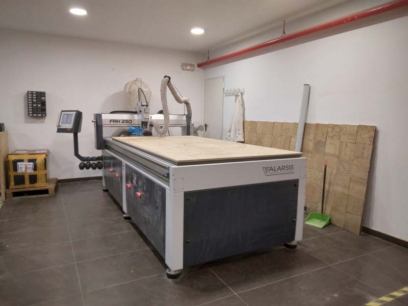
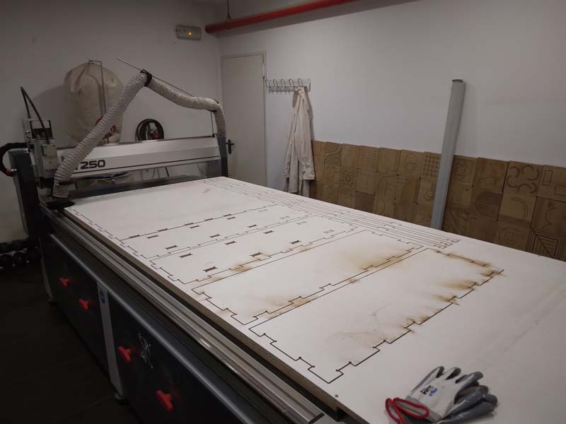
The CNC that exists in the Fab Lab ESNE is the following model.
- Model: Alarsis FRH 250
- Software: VCarve
- Work area: 1250 x 2450 mm
- Bridge height: 150 mm
- This milling machine uses a vacuum table.
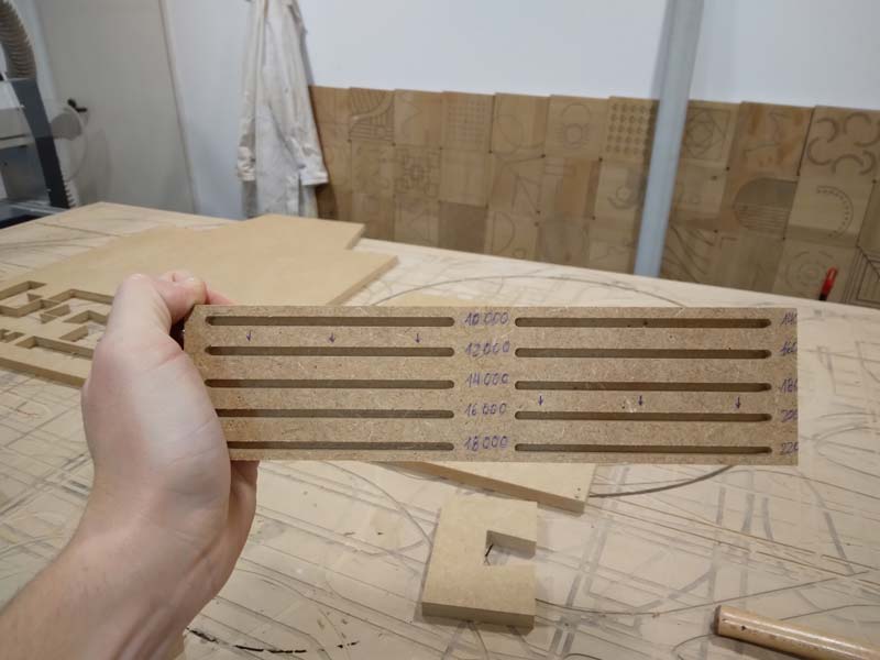
Test of forward speed and revolutions:
I did the tests on a 15 mm thick MDF board, the test is done in two passes of 7.5 mm depth each, with a 6 mm diameter two-flute universal cutter. The first thing I did was to prepare a test to test different rpm on the same material, the best result was at 12,000 rpm. After this test with 12,000 r.p.m. I did the same test with different advances, this time the best result was at 2000 mm/min
0,0 Adjustement:
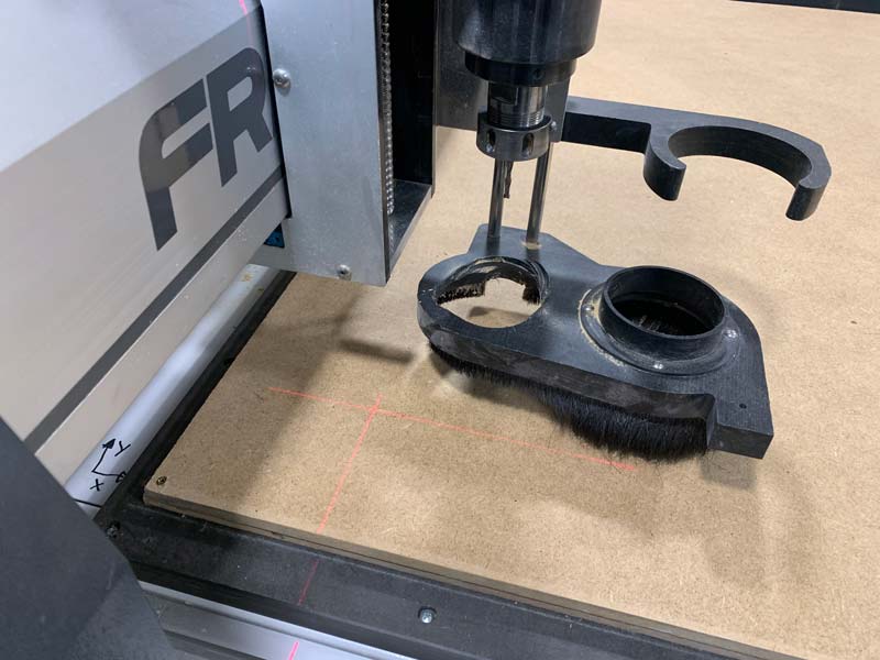
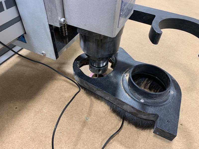
The adjustment of the 0 of the milling machine is simple. In the X and Y axis it is done by activating the laser of the milling machine, this laser draws an X in the material, we must place the X in the point we want and indicate in the milling machine that this is our 0.0. Once this is done, the Z axis is marked by a button on the milling machine and the use of a tracer that we place on the material that we are going to mill.
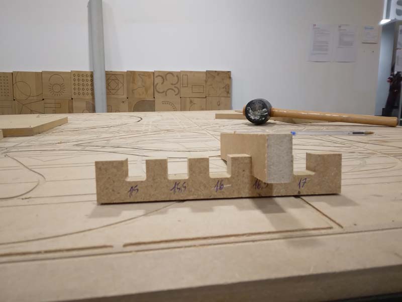
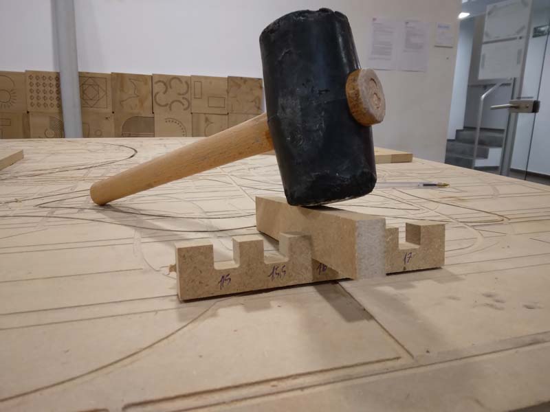
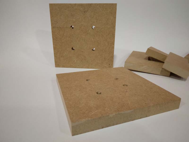
After the speed test, I did an adjustment test between pieces depending on the tolerance left between them, in this case I used a 17 mm thick MDF board, this board entered with the hand in a 16.5 mm slot and with the hammer it can be driven into a 16 mm wide slot.
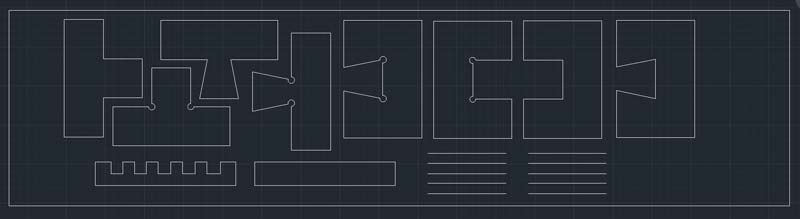
Once the tests were finished, I made two pairs of pieces to see the fit between them using the measurements of the previous tests. I made a straight fit and a diagonal one, I made a couple with dogbones and another without them (I know that the couples without dogbones will not fit but I wanted to keep these tests to show them to the users of the Fab Lab so that they better understand why they should use them)
The cut of the hooks was cut perfectly
After sanding the tabs the fit between the pieces (with a little hammer) was perfect
Individual assignment
Make something big
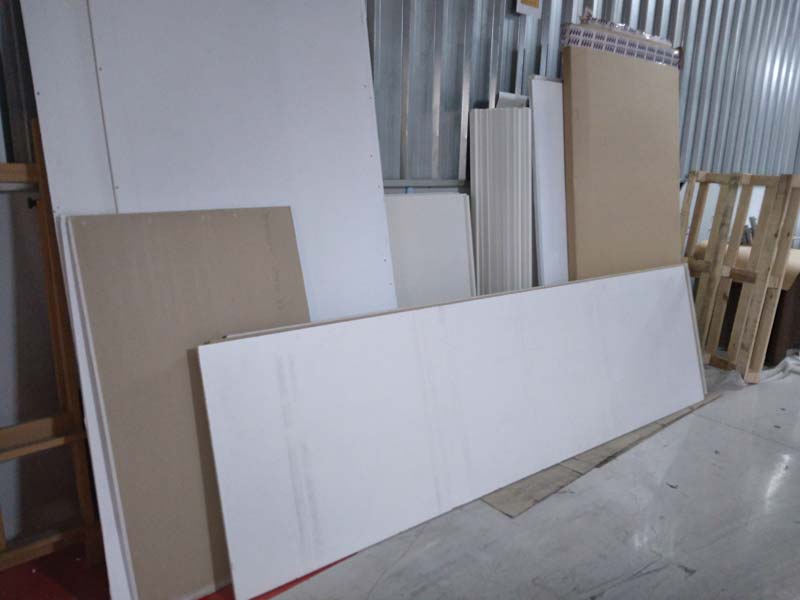
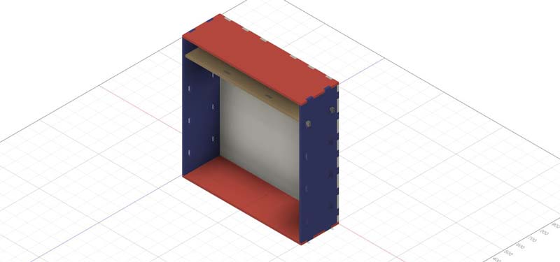
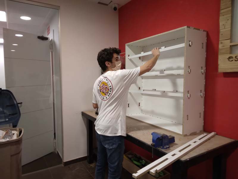
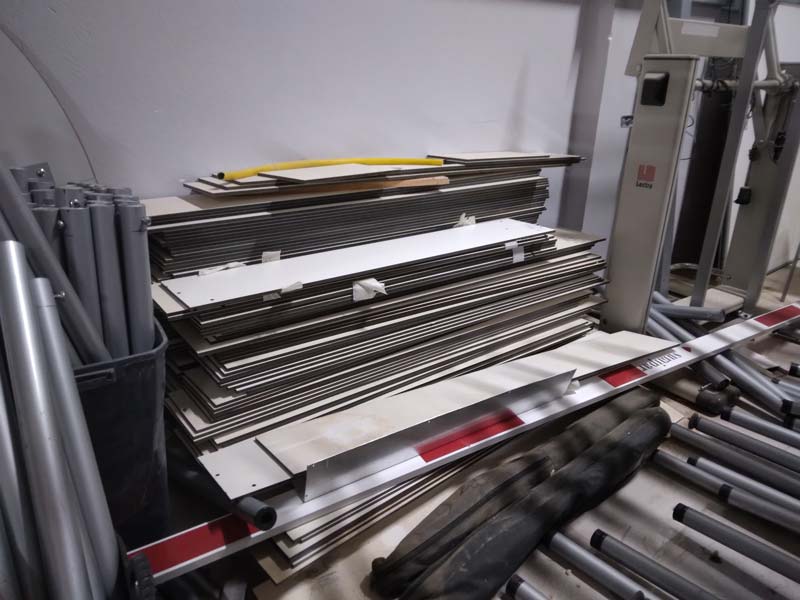
For this task, since I had to do something big, I wanted to make a piece of furniture that I could take advantage of in my Fab Lab, so I designed a shelf to store all the accessories and materials for my ceramic 3D printing WASP. I saw that in the garage of the university there was a large chipboard so I will try to do it in this board so I don’t have to buy more material.
I started modeling the shelf in Fusion 360, I wanted the shelves of the shelves to be modular to be able to adapt to objects of different heights.
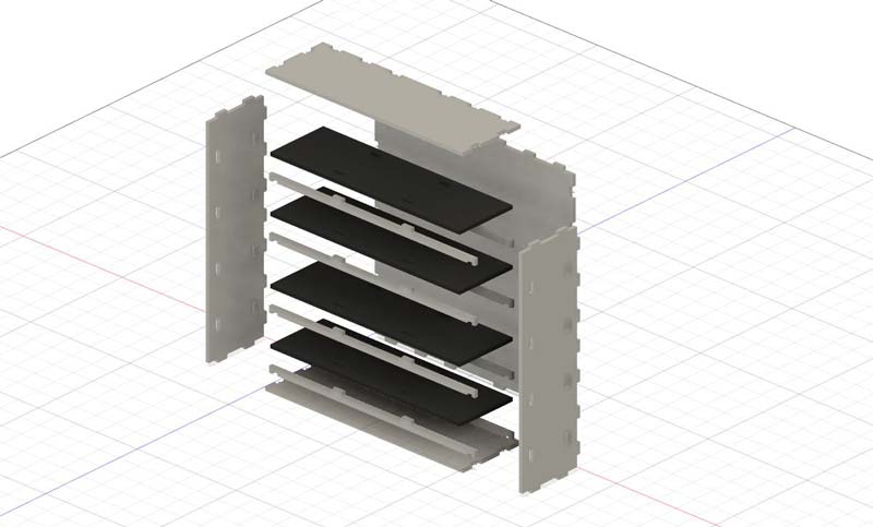
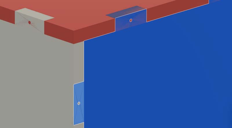
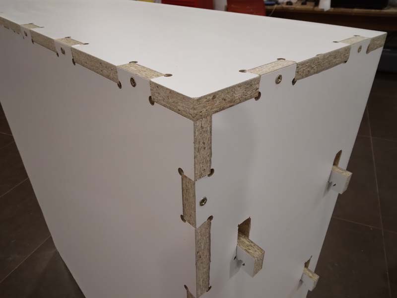
In addition to the sockets between pieces, I designed some holes in the sockets themselves to be able to put a screw in them and that way it would be stronger
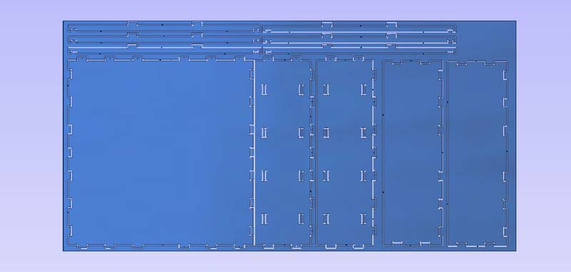
With the design finished, go to AutoCAD to prepare the file for the milling machine
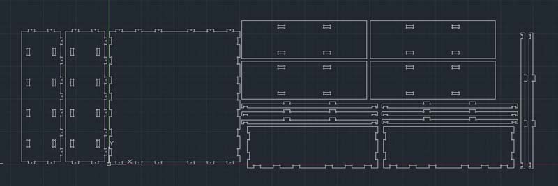
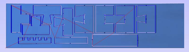
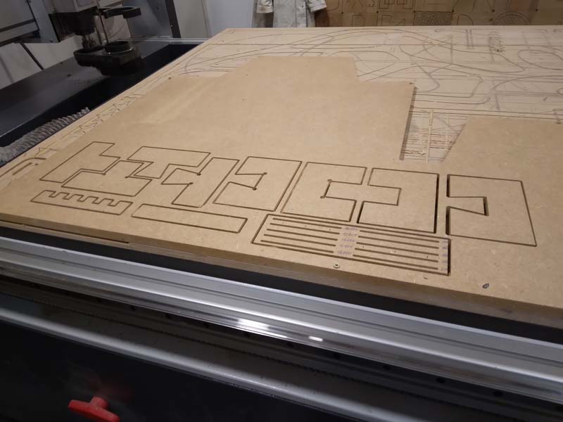
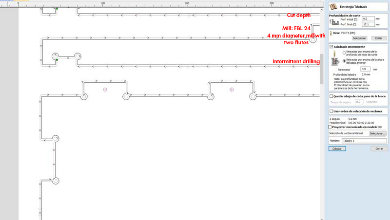
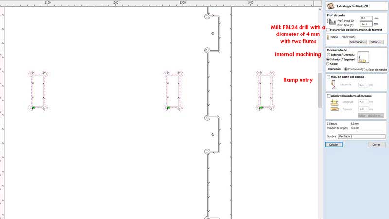
Once the file is finished, prepare the cut in the VCarve, flange holes first. Then the interior cuts of the side panels and finally the exterior cut of all the pieces
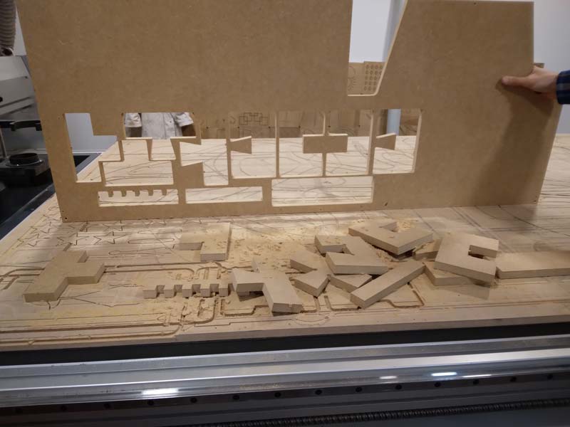
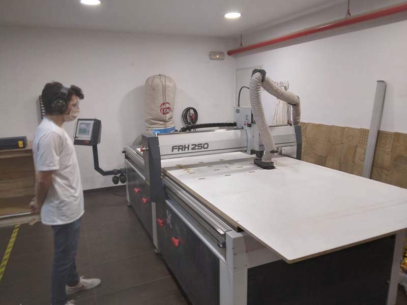
With the file prepared I cut it on the milling machine, always supervising the cut in case there is any problem
With all the cut pieces assemble the shelf, the screws inside the joints made it stay well attached
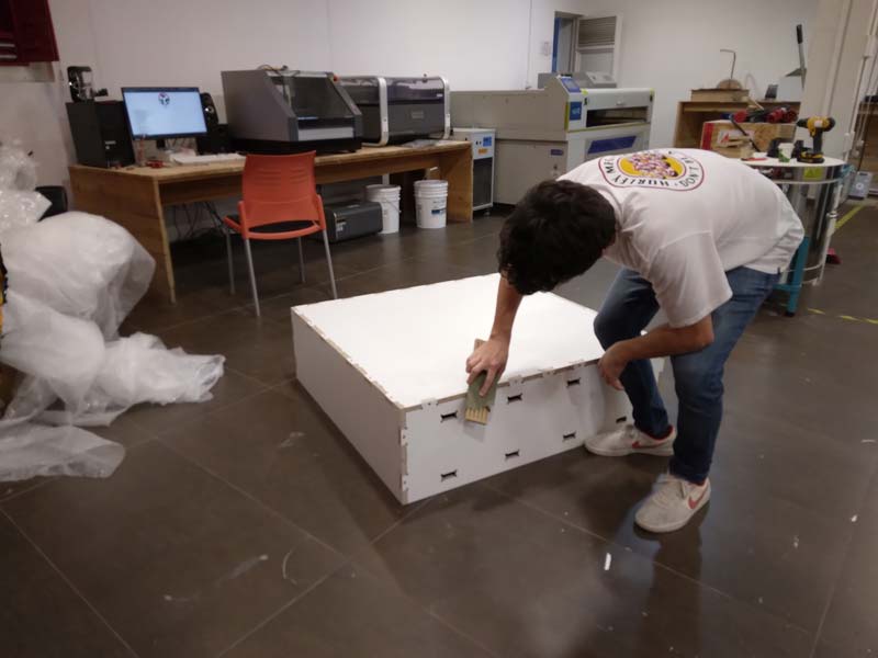
Then sand all the corners a little and mount the inner shelves
Extra credit: Dont use fasteners or glue
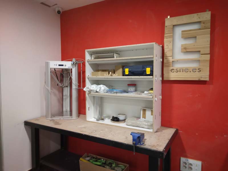
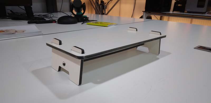
When I went to the garage for material I found several abandoned phenolic panel rectangles. This is a very good material and I wanted to design something to cut with the CNC and take advantage of this material
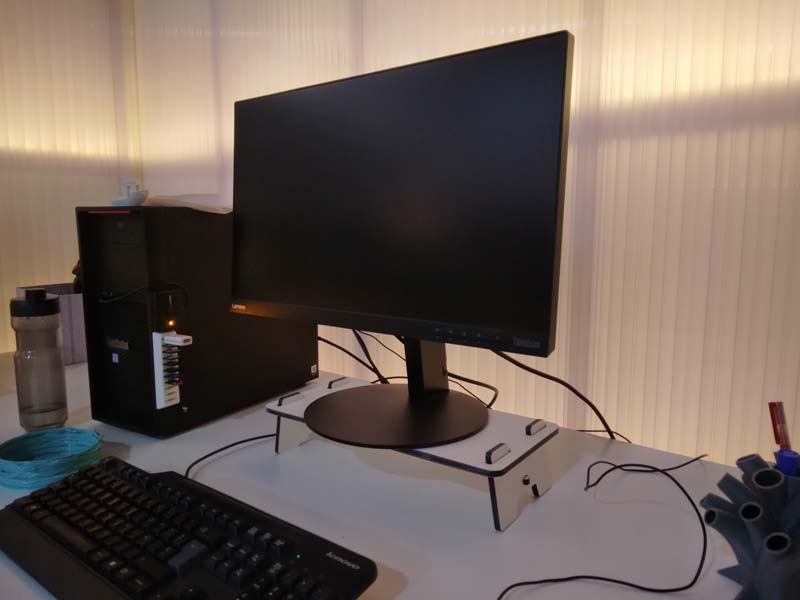
I wanted to elevate my computer screen so I designed a kind of bench for my screen, the bench was a simple two leg structure, as I didn’t want to use screws or glue, the whole would be held together by the bottom slat of the bench that will be on tension and tighten all parts
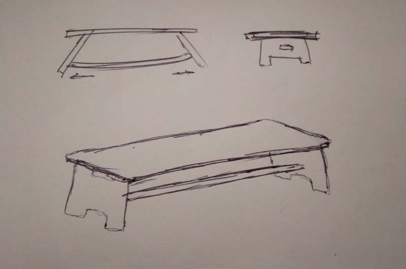
Go model it in Fusion 360 and then modify it in AutoCAD
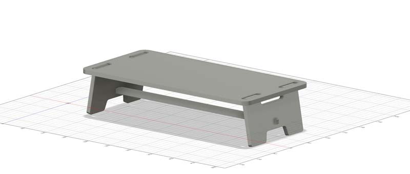
Then I prepared the file for the milling machine and cut the pieces
It is important to always supervise the work of the milling machine in case an error occurs to be able to react quickly
Download archives
Shelving .dxf
Shelving .f3d
See you next week!