Final project development
Development spirals
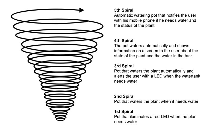
When I chose the final idea for my project, I proposed a series of spirals, each one more ambitious than the previous one. The spiral that I have decided to develop for my final project is the third one, which includes two independent systems. On the one hand, the water level system that has two level sensors to know how much water is in the tank and a neopixel LED to show different colors depending on the water in the tank. On the other hand, the automatic irrigation system has a humidity sensor that measures the water in the ground, on the other hand, a water pump that irrigates the plant if the humidity sensor detects that the ground is dry.
The decision to reach the third spiral was mainly due to the leap to incorporate an OLED screen in the pot, it was too big to do it, also I have always had a very limited time to develop the final project and the goal had to be realistic with the time that I was going to dedicate So my project is a pot with an automatic watering system that notifies the user by means of the color of an LED how much water is left in the tank of the pot. To fill it in if necessary.
Modeling
Previous models
The first three models were part of the final project proposal section
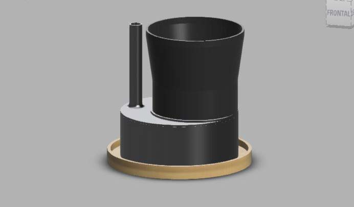
Modeling v4
In the development phase of my project I started modifying the 3d modeling of the pot, the last idea of my proposal was a pot that would measure about 120 centimeters in height, due to the time I had left I decided to make a tabletop version since it would be more affordable to make in the time I had left.
After doing this modeling I started to print the main pieces to see them at 1:1 scale and to be able to test the operation
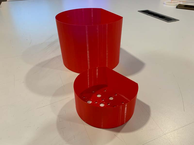
After testing the pieces, I realized that the pot was too small and the water tank too large, so I corrected several measurements and redid all the modeling again, adapting these measurements.
Modeling v5
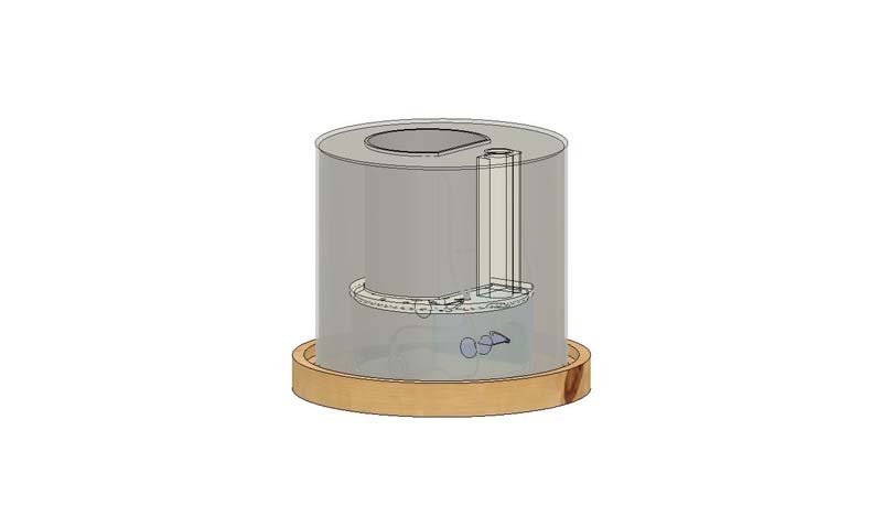
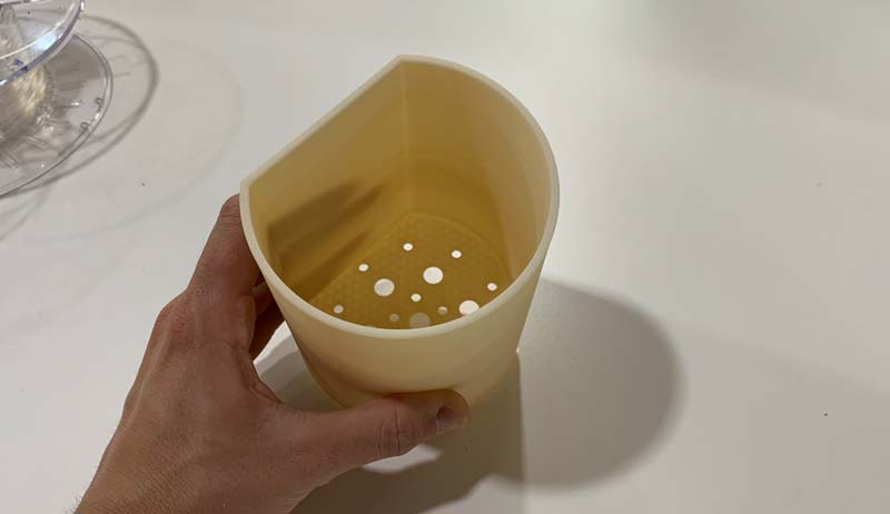
With this new modeling I started to produce all the necessary parts for my final project, the inner pot, the water tank and the lid were printed in ABS on an Ender 3 v2.
Diagram of parts of Smart Pot and its operation
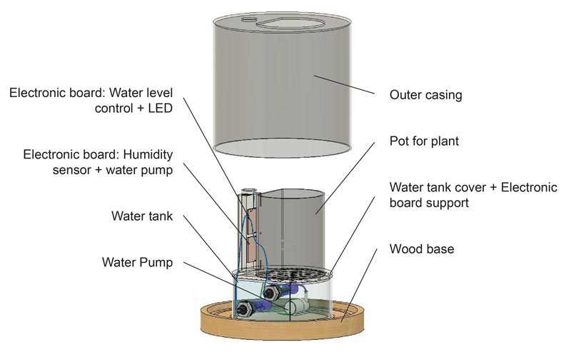
3D printed parts and post processing
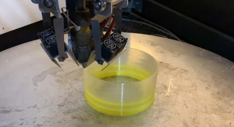
I printed all the parts without problems, but the water tank was leaking water, I tried to print it on the WASP 3MT, but the walls were too thick so I printed it on an Ender and applied a layer of resin to make it totally waterproof.
Then I went to print the outer cylinder of the pot on the Delta WASP 3mt, this cylinder acts as the outer casing in addition to holding the lid of the pot.All Smart Pot 3d printed parts are made with PLA.
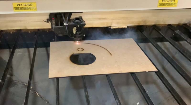
Laser cut parts
Once the outer cylinder is printed, I laser cut the cylinder cover, the cover is part of the housing part and fits with the 3d printed parts of the interior. This piece is made of 5 mm thick MDF board.
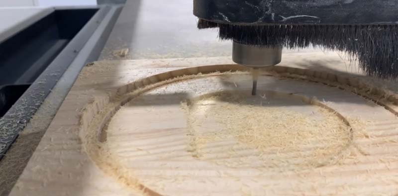
Milled parts
The next step was to manufacture the base of the pot in the milling machine. This base supports the 3d printed parts and the outer casing thanks to a hollowing out in the shape of each of the pieces. The base is made of 20 mm thick pine wood, then it was sanded and varnished.
Electronics
Smart Pot has two different electronic systems, each of these systems has its inputs and outputs, but they work independently. This facilitates the debugging task since it allows studying the electronic circuits separately.
Water level meter system and LED indicator
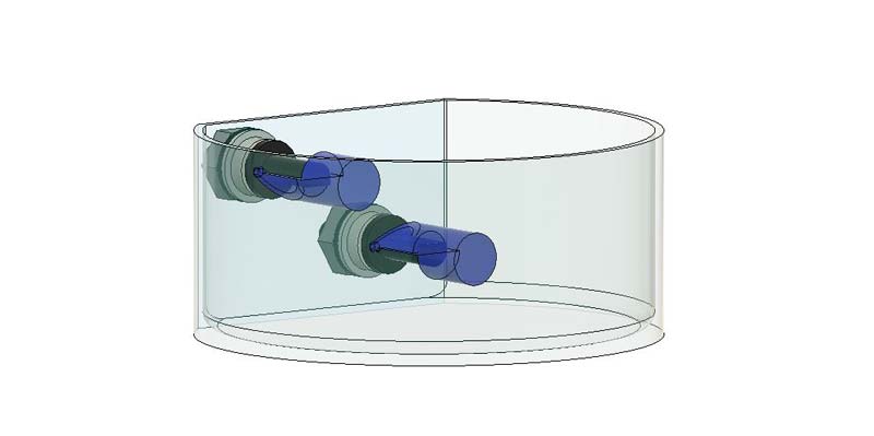
System operation
The first system consists of two level sensors as inputs and a Neopixel LED as output, the operation of the system is as follows: There is a level sensor in the lower part of the tank and another in the upper part, each of these sensors can be high or low, the sensor is high when the moving part is aligned with the body and low when this part is no longer aligned.
As the lid of the water tank has a tube up to the surface of the housing, the water tank can be refilled by pouring water through the hole in the lid until the LED turns green.
With these two values and the position of the two sensors in the tank, we can know if the tank is full, half or almost empty, as we can see explained in the following images.
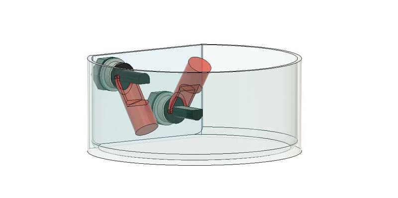
LOWER SENSOR CLOSE & UPPER SENSOR OPEN
The lower sensor is high, the water level is too low, the LED light will be red
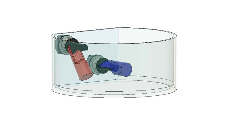
LOWER SENSOR OPEN & UPPER SENSOR OPEN
Both sensors are low, it means that there is an average level of water that lifts the two moving parts, the LED light will be yellow
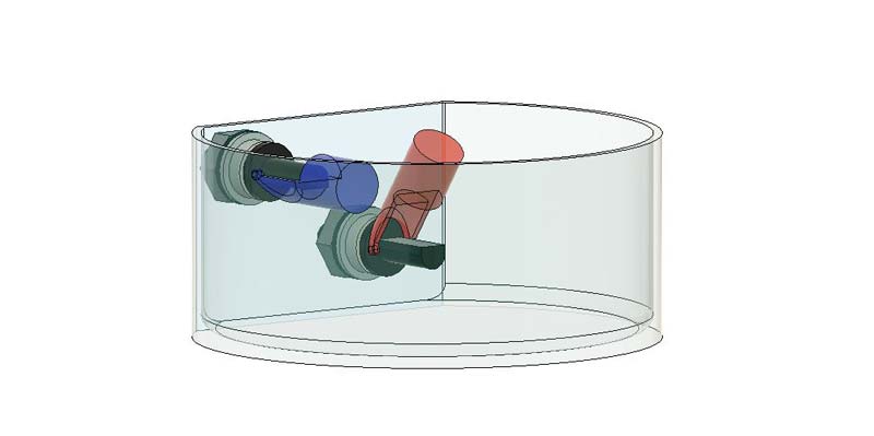
LOWER SENSOR OPEN & UPPER SENSOR CLOSE
The upper sensor is closed so the water level is too high, the LED light will be green
LOWER SENSOR CLOSE & UPPER SENSOR CLOSE
It is physically impossible for both sensors to be high, in this case the LED flashes between blue and red to indicate that there is an error.
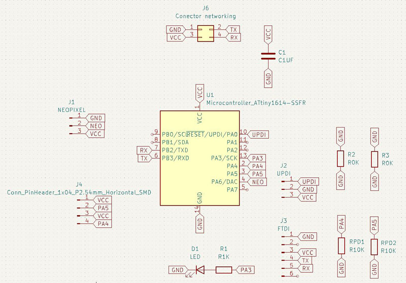
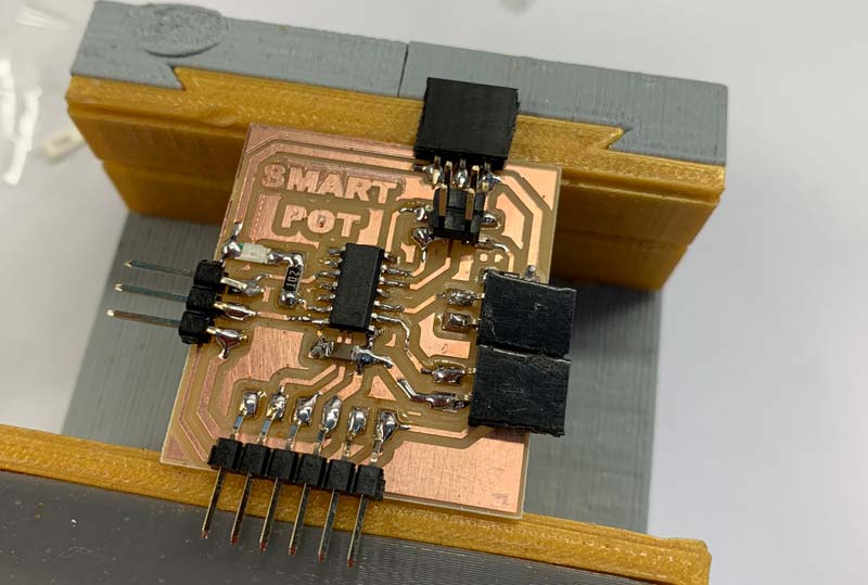
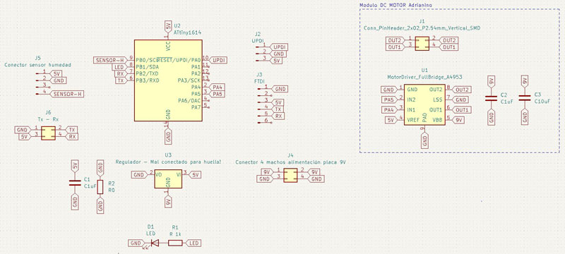
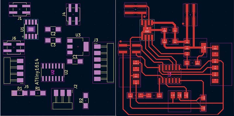
Board design
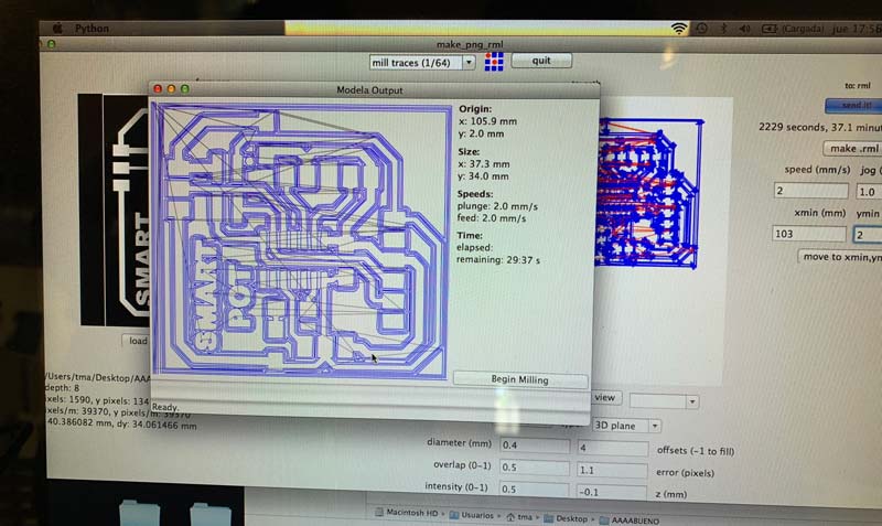
I designed my board in KiCAD, the board works with an Attiny 1614 microcontroller, in which I have connected a normal LED to be able to do tests, the neopixel LED that indicates the water level and inputs for the level sensors. In addition to the pins for UPDI, FTDI and Tx Rx.
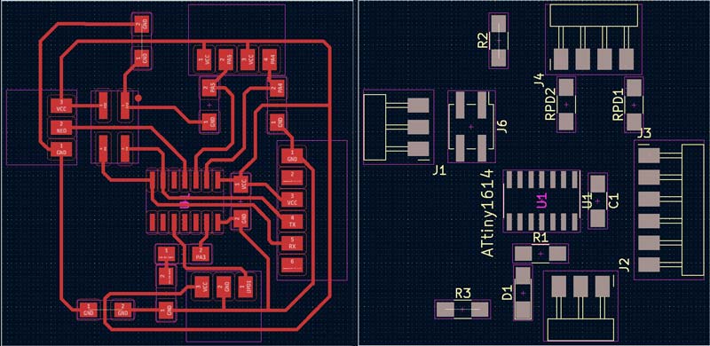
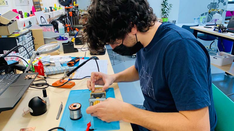
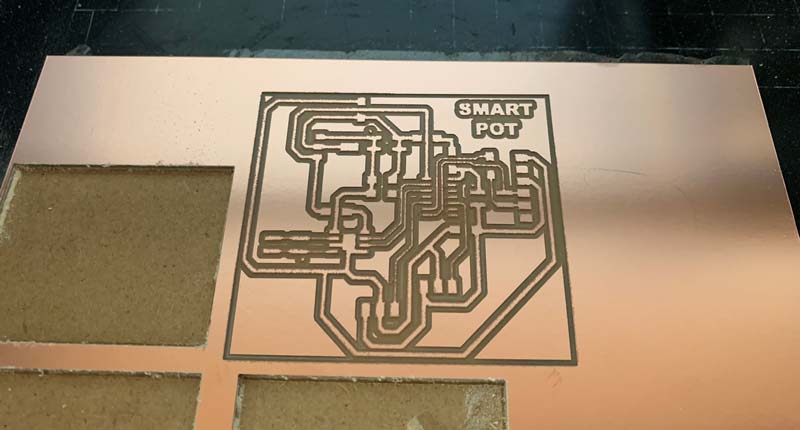
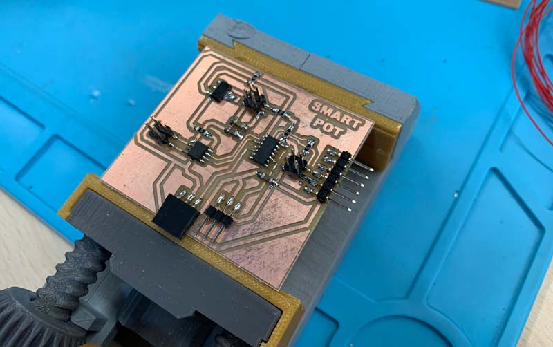
With the design of the board, I milled the PCB in my roland model to later solder all the components and start programming.
Programming
To program this board it is necessary to install the Neopixel libraries, you can see how in my assignment of outputs. After programming the board for the first time, I did several tests with the sensors and LEDs until everything worked correctly.
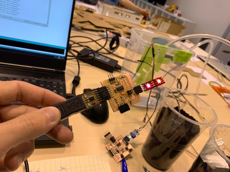
The most problematic part was the neopixel LED, since I had never used it before, but with a little time and the help of my colleagues at Fab Lab León, I managed to program it correctly.
This is the program I used for this board:
//Pablo Pastor for Fabacademy 2022
//Original code by Adrian Torres, with the help of Luis Diaz and Pablo Nuñez

#include <tinyNeoPixel.h>

#define PIN 2 //  Pin de control

// Parameter 1 = number of pixels in strip
// Parameter 2 = Arduino pin number (most are valid)
// Parameter 3 = pixel type
//   NEO_GRB     Pixels are wired for GRB bitstream (most NeoPixel products)
//   NEO_RGB     Pixels are wired for RGB bitstream (v1 FLORA pixels, not v2)
//   NEO_RGBW    Pixels are wired for RGBW bitstream (NeoPixel RGBW products)

tinyNeoPixel strip = tinyNeoPixel(1, PIN, NEO_GRB + NEO_KHZ800);

int abajo;
int arriba;

void setup()
{

Serial.begin (115200);
pinMode (0,INPUT);
pinMode (1,INPUT);
Serial.println ("Hola");

strip.begin();
strip.show(); // Initialize all pixels to 'off'

}

void loop()
{

  abajo = digitalRead(0);
  arriba = digitalRead(1);
  Serial.println ("Arriba");
  Serial.println (arriba);
  Serial.println ("Abajo");
  Serial.println (abajo);

//strip.setPixelColor(0, 200,0,0); //Show red on the first LED (The first LED is the LED 0)(R)(G)(B)
//strip.show();


if (arriba == 0 && abajo==1)
{
  strip.setPixelColor(0, 200,0,0);
  strip.show();
}

if (arriba == 0 && abajo==0)
{
  strip.setPixelColor(0, 150,100,0);
  strip.show();
}

if (arriba == 1 && abajo==0)
{
  strip.setPixelColor(0, 0,150,0);
  strip.show();
}

if (arriba == 1 && abajo==1)
{
  strip.setPixelColor(0, 0,0,150);
  strip.show();
  delay (500);
  strip.setPixelColor(0, 50,00,0);
  strip.show();
  delay (500);

}

}
Moisture and irrigation measurement system
System operation
The Smart Pot automatic irrigation system has a soil moisture sensor as input and a water pump as output. The sensor is inside the casing nailed to the soil of the pot. The water pump is inside the water tank. The humidity sensor is constantly measuring the humidity levels of the soil, when these levels are low it sends the water pump to irrigate the soil for a few seconds. After a few minutes, it will measure the humidity again in case it is necessary to water again.
Board design
I designed my board in KiCAD, the board works with an Attiny 1614 microcontroller, in which I have connected a normal LED to be able to do tests, the neopixel LED that indicates the water level and inputs for the level sensors. In addition to the pins for UPDI, FTDI and Tx Rx.
With the design of the board I milled it in the Fab Lab in Leon with the help of Adrián and Nuria to later weld it.
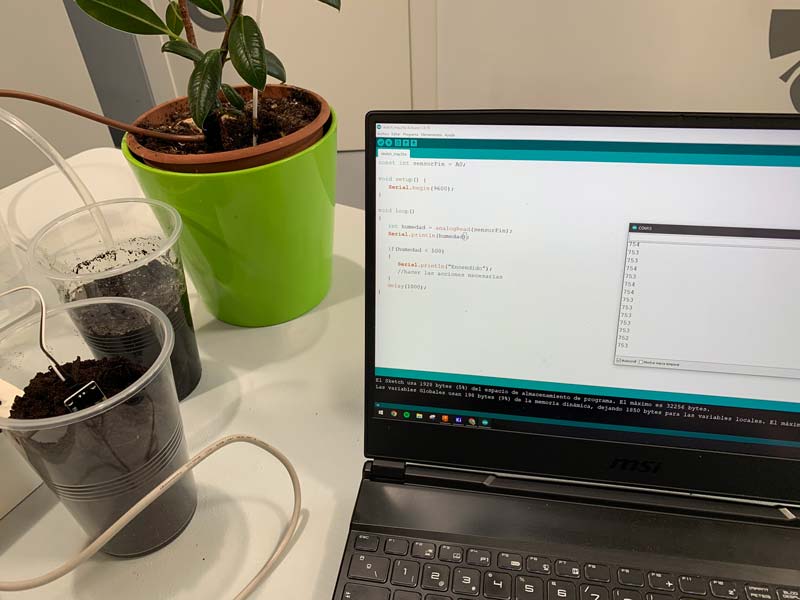
Programming
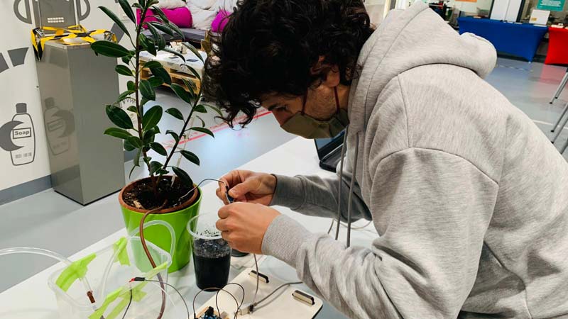
For this board I had to do several tests of how the humidity sensor measurements worked to adapt the sensor values to the activation of the water pump.
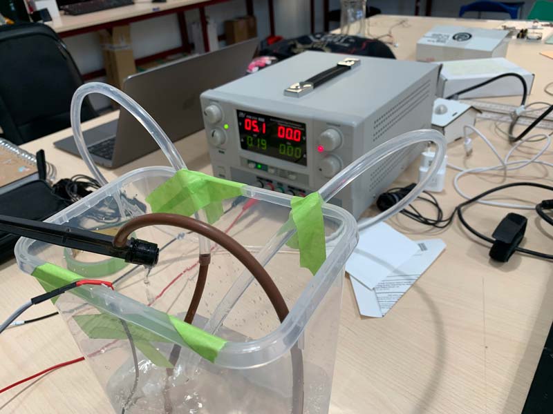
I started doing several tests to familiarize myself with the sensor and the measurements it took, preparing samples of dry, humid and wet soil to know what values it marked in each one of them.
This is the program I used for this board:
//Pablo Pastor for Fabacademy 2022
//Original code by Adrian Torres, with the help of Luis Diaz and Pablo Nuñez

const int motor1Pin = 0;      // H-bridge pin 0 (in2)
const int motor2Pin = 1;      // H-bridge pin 1 (in1)


void setup() {
    //Paso 1
    Serial.begin(115200);
    Serial.println("Valor del sensor de humedad");

    // set H-bridge pins as outputs:
    pinMode(motor1Pin, OUTPUT);
    pinMode(motor2Pin, OUTPUT);
}

void loop() {
    //Paso 2
    int humidity = analogRead(7);
    Serial.print("Humedad de la tierra: ");
    Serial.println(humidity);
    //Paso 3

    if(humidity >= 0 & humidity <= 325){
       Serial.println("Sensor en suelo húmedo");
             analogWrite(motor1Pin, 0); // set pin 1 of the H-bridge to 50% using PWM
             analogWrite(motor2Pin, 0);   // set pin 2 of the H-bridge to low state
    } else if(humidity > 325){
        Serial.println("Sensor en suelo seco");
              analogWrite(motor1Pin, 127); // set pin 1 of the H-bridge to 50% using PWM
              analogWrite(motor2Pin, 0);   // set pin 2 of the H-bridge to low state
    }else if(humidity = 1023){
        Serial.println("Sensor desconectado de la tierra");
    }
    delay(200);
}
Final assembly
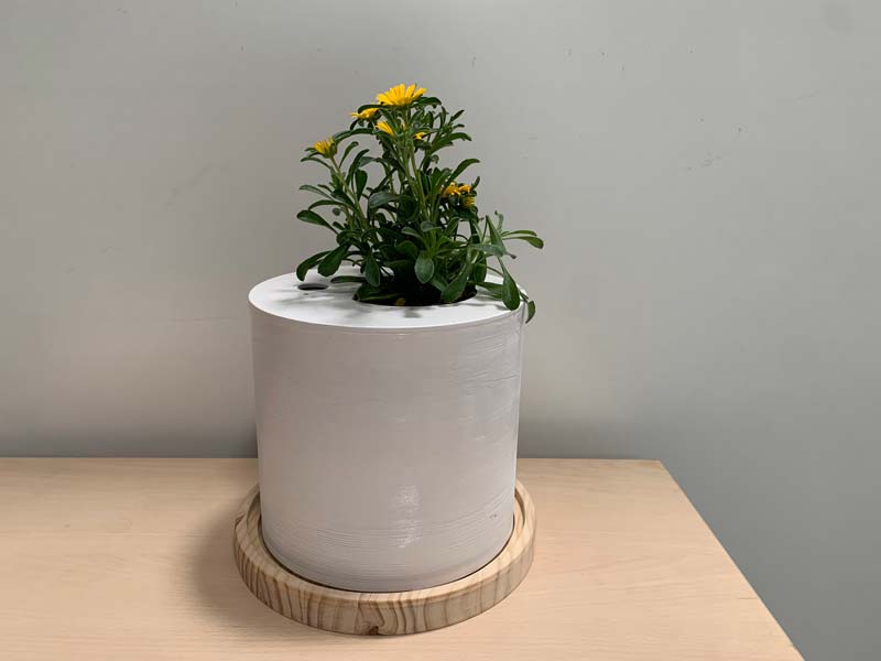
With all the parts manufactured and the boards working correctly, all that remains is to do the final assembly of Smart Pot with your plant.
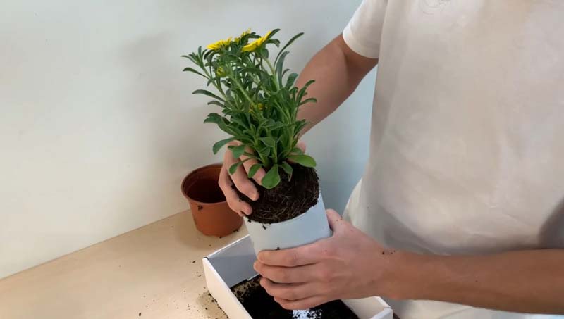
Start by placing the lower wooden base, on this we will place the water tank, inside we will put the water pump already connected to its conduit and on top of it the piece that connects it with the outside, in this piece the two electronic boards are placed and the neopixel LED.
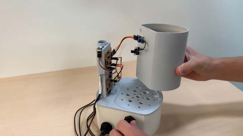
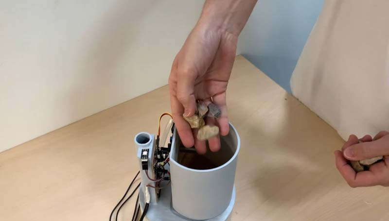
We place all the electronics in their position and the power supply of the pot, we can now place a stone base with a filter in the pot and then fill it with soil to put our plant inside it.
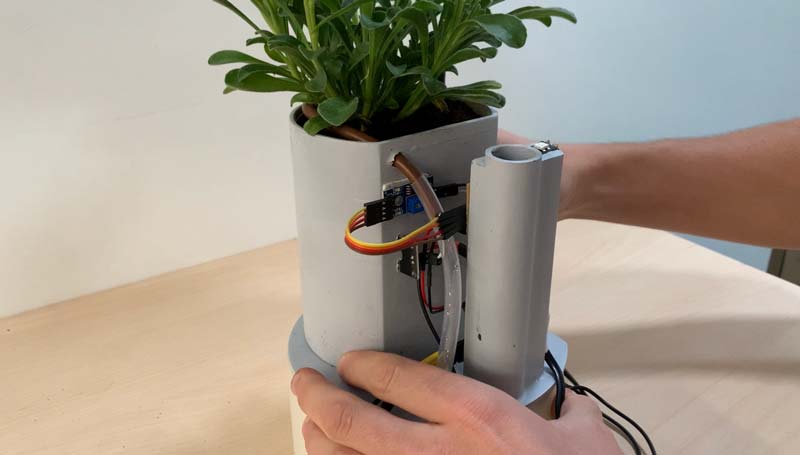
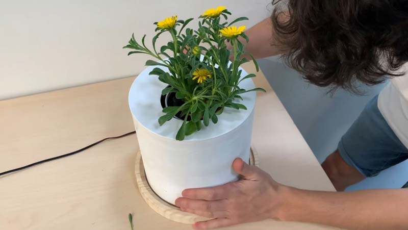
Finally we only have to place the exterior casing adjusted to the base.
BOM
Components for the manufacture of the pot
| Component | Quantity | Cost |
|---|---|---|
| Wooden board 30 mm | 400x400 mm | 6,20 $ |
| MDF board 3 mm | 400x400 mm | 2,10 $ |
| PLA for 3D printing | 500 gr | 18,50 $ |
| Water pipe | 300 mm | 0.40 $ |
| 12 x Colored wires | 200 mm | 2,20 $ |
Level sensor board and LED
| Component | Quantity | Cost |
|---|---|---|
| Attiny1614 | 1 | 1,01 $ |
| 2-pin female connector | 2 | 0,52 $ |
| 3-pin female connector | 1 | 0,52 $ |
| 3-pin male connector | 2 | 0,19 $ |
| 4-pin male connector | 2 | 0,19 $ |
| 6-pin male connector | 2 | 0,19 $ |
| Neopixel LED | 1 | 0,28 $ |
| R 1K | 1 | 0,04 $ |
| Capacitor 1uF | 1 | 0,03 $ |
| R 0K | 1 | 0,05 $ |
| Level sensor | 2 | 6,00 $ |
Humidity sensor board and pump
| Component | Quantity | Cost |
|---|---|---|
| Attiny1614 | 1 | 1,01 $ |
| 4-pin female connector | 2 | 0,52 $ |
| 3-pin female connector | 1 | 0,52 $ |
| 3-pin male connector | 2 | 0,19 $ |
| 6-pin male connector | 2 | 0,19 $ |
| Driver Allegro | 1 | 3,60 $ |
| Capacitor 1uF | 2 | 0,03 $ |
| Capacitor 10uF | 1 | 0,03 $ |
| Regulator lm2940 | 1 | 2,40 $ |
| R 0K | 5 | 0,05 $ |
| Water pump | 1 | 2,95 $ |
| Humidity sensor | 1 | 2,40 $ |
Total cost of 1 Smart Pot = 52,14 $
Final conclusion
My final conclusion about the final project and all the tasks that I have been doing during the Fabacademy is that it would have been ideal to have had more time to dedicate each week to each of the assignments, on the one hand to complete the assignment and on the other to work on the assignment. part of that week’s homework related to my final project. Since I finally had to do all the development of the final project during the last month, especially during the last week with more rush than I would like. On the other hand, despite all the difficulties, I am happy with the final result of the project. It is true that I would have liked to change certain parts to facilitate the assembly and adjustment of the set, but I understand that everything can be improved and I do not consider my final project finished. It has only been a first functional version of what I want to do. On a personal level, I have learned to efficiently manage the little free time I had to dedicate to my assignments, as well as to solve problems that have arisen throughout the process in the fastest and most functional way, all of which would not have been possible. without the help of my colleague Luis who has helped me at all times and all the staff of the Fab Lab León who have been infinitely patient with me :)
Download files
Water level meter system and LED indicator .png
Moisture and irrigation measurement system .png
All .stl of manufactured parts .stl
Enjoy!