Electronics production
This week, there are two types of assignments, one group and one individual. In my case i’m alone in ESNE’s Fab Lab so I do both.
Assignments
Group assignment:
- Characterize the design rules for your in-house PCB production process
Individual assignment:
- Redraw an echo hello-world board.
- Add (at least) a button and LED (with current-limiting resistor).
- Check the design rules, make it, and test that it can communicate.
- Extra credit: simulate its operation.
Group assignment
Group assignment page
In the following link you can access the Leon Fab Lab page that contains all the group assignments: Fab Lab Leon group assignment page
Characterize the design rules for your in-house PCB production process
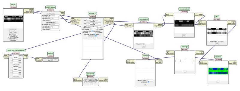
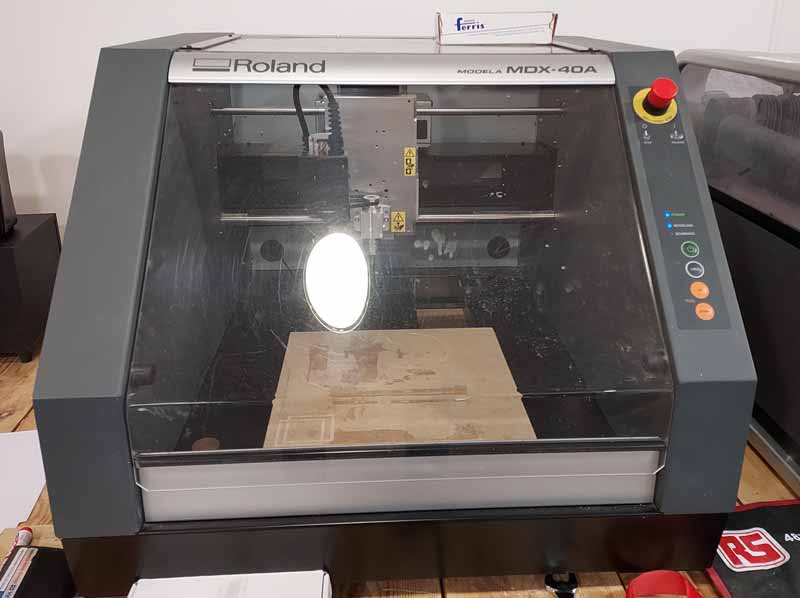
In my Fab Lab we have a Roland Modela MDX 40A, the machine can be controlled from the computer using the VPanel, with this program we can move the head and the bed of the milling machine. With VPanel we mark 0.0 on the X and Y axis, we will also mark 0 on the Z axis using a probe.
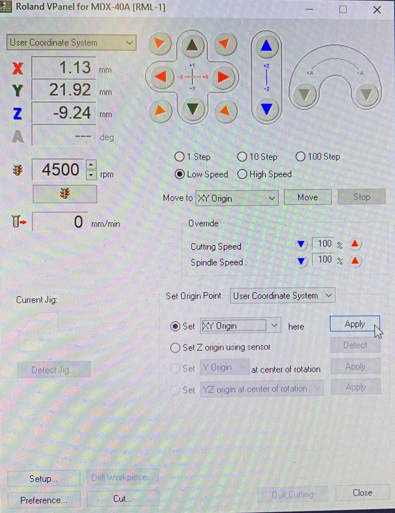
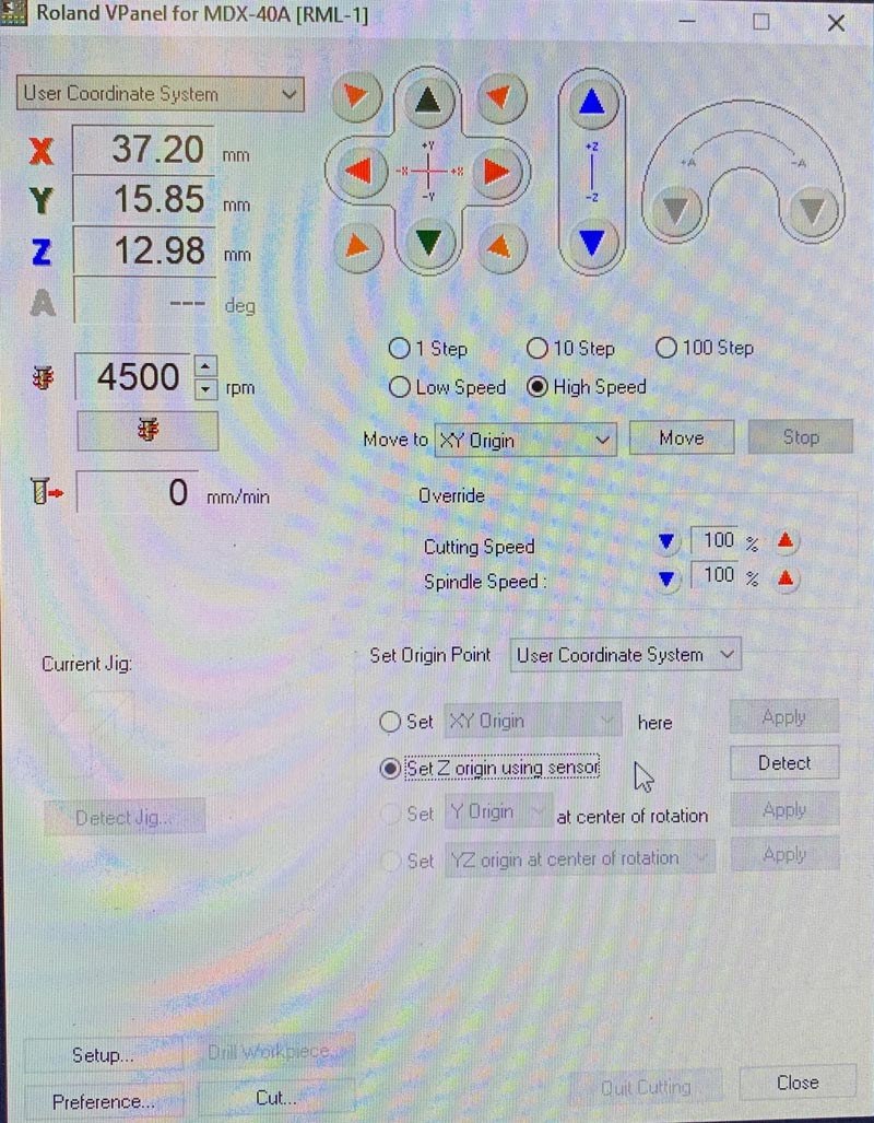
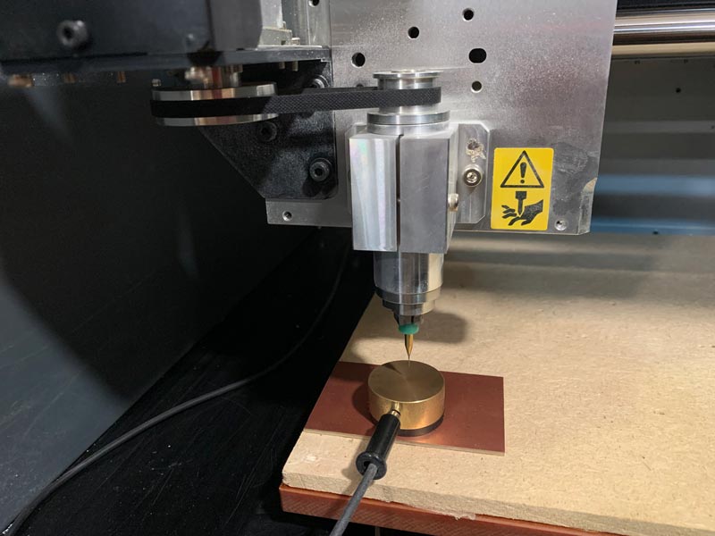
Once the three 0’s have been marked, all that remains is to load the mods file and mill it.
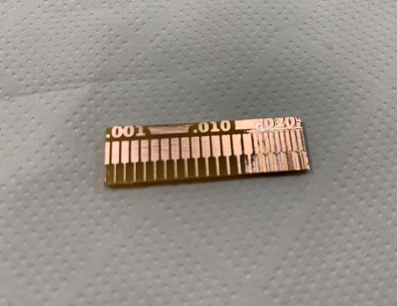
I had some problem in the leveling in Z of the right part but the test works perfectly for me
Individual assignment
Using the Roland MDX-40A for the first time
This week I had to use the small milling machine from my Fab Lab, this was the only machine I had never used and had never seen anyone use, so the first thing I had to do was learn how to use the machine from the beginning and then do my homework weekly
The small milling machine in my Fab Lab is a Roland modela MDX-40A
So the first thing I did was follow this tutorial that my local instructors share with me. The tutorial is from Aalto’s Fab Lab, this tutorial seemed very good to me and it helped me a lot to learn how to use the milling machine with mods, I recommend it to everyone who has this milling machine.
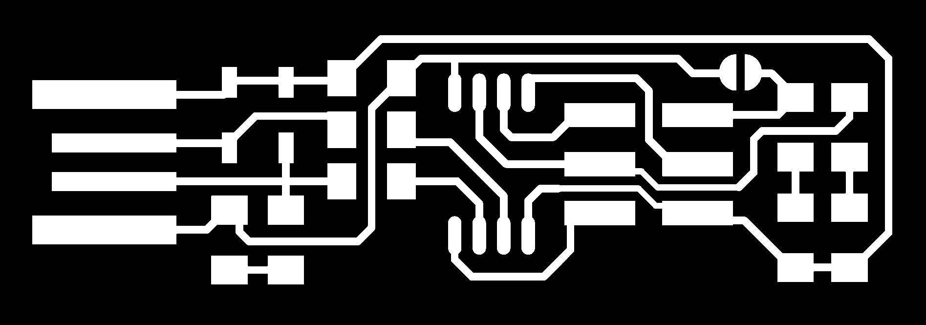
After watching the tutorial a couple of times I tried milling this FabTinyISP of Brian. files.
I started using a broken bur for testing, but the only thing I got was milling a horizontal straight line
I went over everything several times and went back to see the tutorial, I did everything from the beginning but I went back to milling a straight line
When I was already starting to freak out, I looked at all the mod figures and realized that in the second box my file size was too big, so the horizontal line was the first line of the file but much bigger than what should be
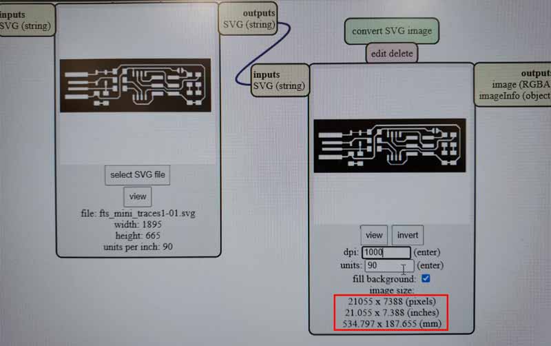
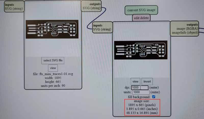
After checking that the size of my svg was correct, I put 1000 in the units block, I don’t know why(The larger the unit block number, the smaller the size of the image I wanted to mill), but putting 1000 in this block the size that shows mods is correct
When I managed to make the program with the correct size I did the first cutting test with a broken bur that I had in the Fab Lab
This time I managed to mill something more than a straight line although the result was not very good
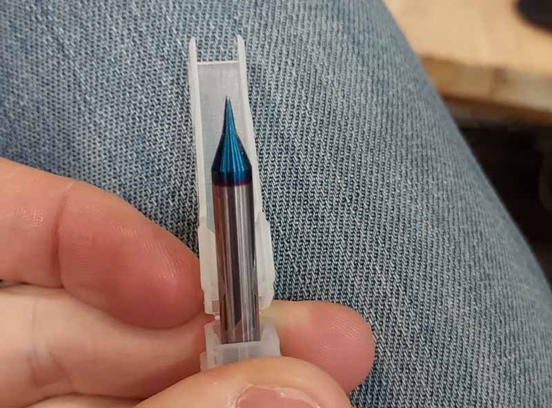
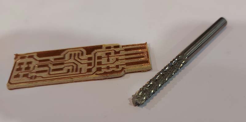
My local instructor, Nuria, sent me a pack of burs for this week, the problem I had was that my router can’t grab burs smaller than 4mm because I don’t have the necessary head (I’ll buy it)
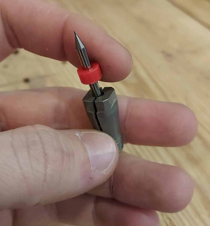
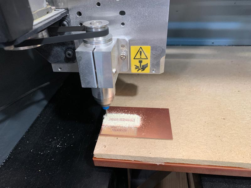
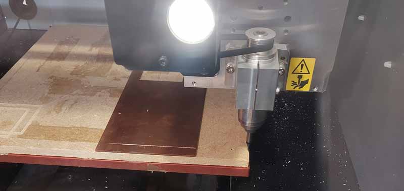
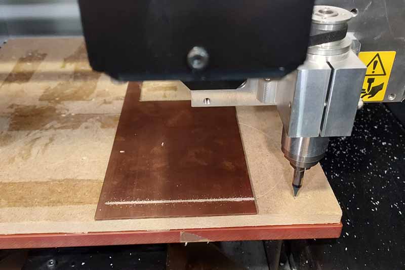
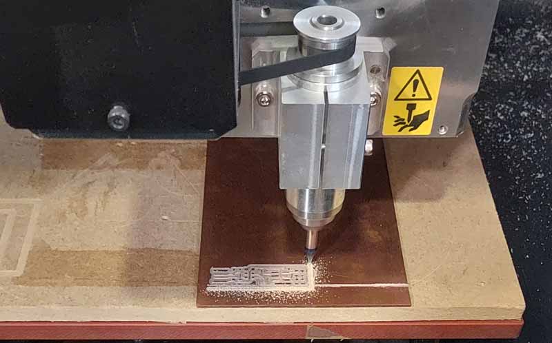
So I couldn’t use the tools that Nuria sent me. So I tried to mill the traces with the 90º engraving milling cutter of my big milling machine.
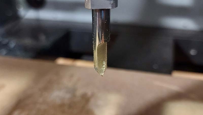
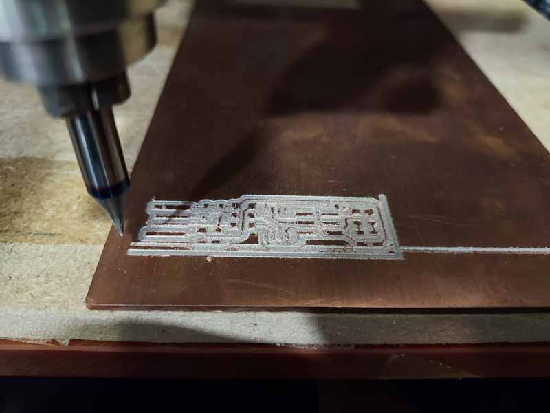
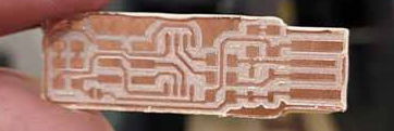
After making the gcode with mods the result was very good
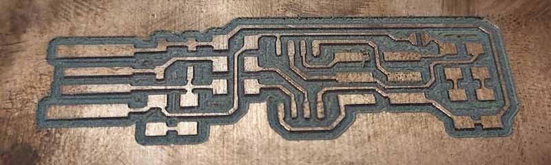
Then mill the outer contour with the broken milling cutter.

The contour was somewhat wrong but it was worth it to try
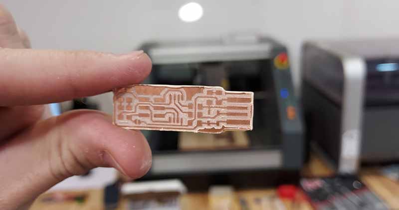
Then remove the excess from the tip and sand the contour a little
First attempt at welding
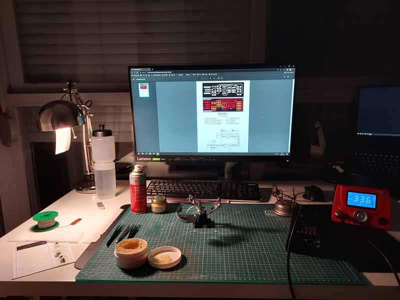
Friday night 22:00, I came home with a plate that seemed fine. I grabbed all the tools I thought I might need from the Fab Lab and set out to solder electronic components for the first time.
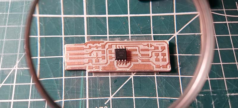
I am lucky to meet Adrian Torres (I recommend everyone to visit his website), at that time I was talking to him and my local instructors and Adrian gave me his timelapse soldering the FabISP so that I could follow the same order as him, start by soldering the microcontroller.
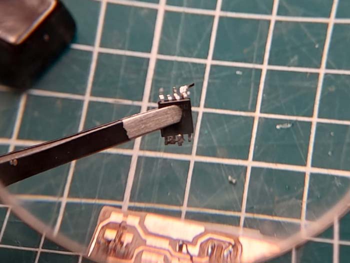
After soldering the microcontroller, try to solder the LEDs, but burn the pad on the board
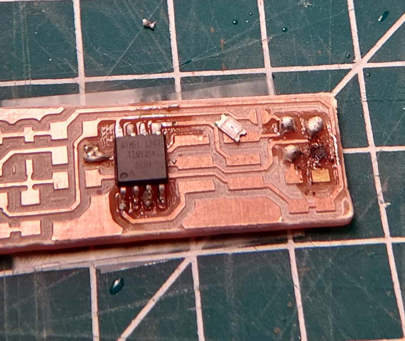
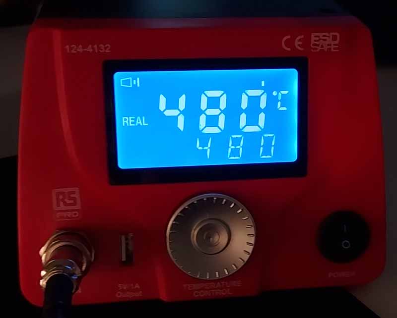
Talking to Adrian, he told me 2 mistakes I was making: The diameter of my soldering iron was too big and the temperature of my soldering iron was too big.
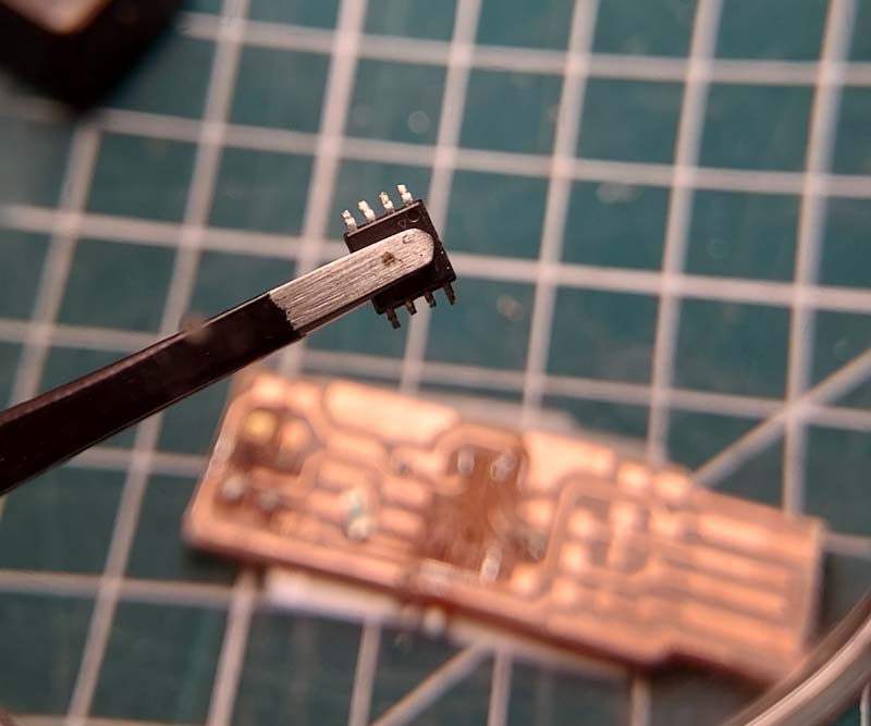
After messing up the first board I desoldered the microcontroller for Monday to mill a new board and try again
Mill a new plate
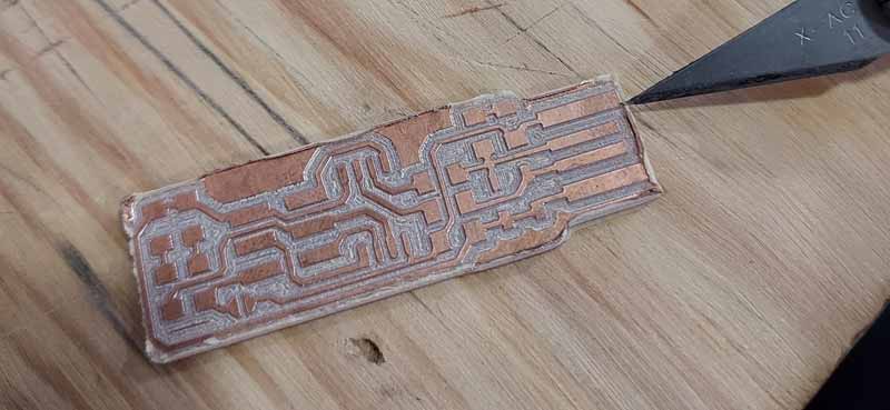
On Monday at the Fab Lab I went back to milling a new board to re-solder the components. In the first one I had a problem in the leveling of the z axis and some parts were left unmilled.
I milled another plate again, but this time I changed the tool for the contour using a FRUT 4 on the large mill for a better finish.
But I forgot to change the diameter of the tool in mods and the FRUT4 shorted part of the circuit :(
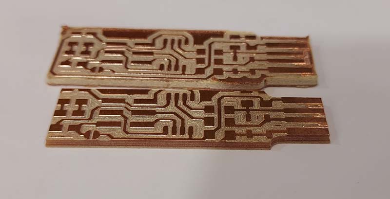
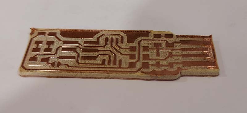
Then I milled another plate again (for the sixth time), this time I got a good plate
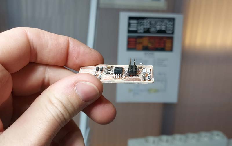
Solder components to the board
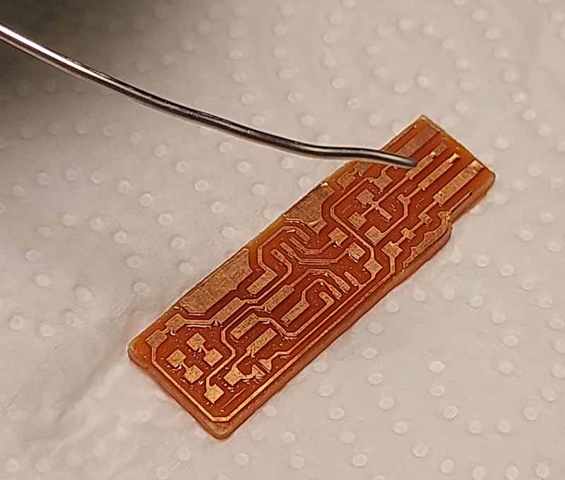
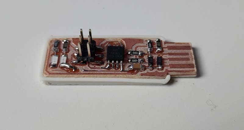
With the good board, 0.5mm diameter tin, the thinnest tip of my soldering iron and a temperature of 200-210 º (Thanks again Adrian) I’m back to try to solder the components to the board
Then I printed Adrian’s shell for my programmer
Program the programmer
Then try to program my programmer following this tutorial Connect my programmer and the one my local instructors sent me from Leon to two different computers
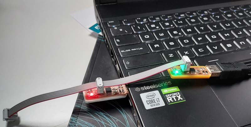
After following the tutorial and with the help of Adrian Torres at the Fab Lab in León, we started by doing the make flash to erase all the previous information and then we did the make fuse, I was able to program my programmer for the first time.
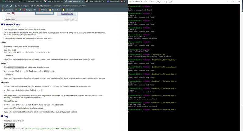
This was the list of commands we used to get it
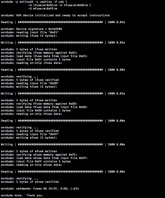
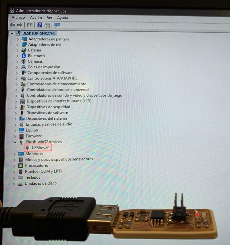
After these steps my computer correctly detected my programmer
See you next week!