8. EMBEDDED PROGRAMMING
This week is all about learning how to program an embedded microprocessor. I don’t have background in this subjects, so it is again a week full of tutorials and workshops from Kamakura’s Team and my teammates (Jans and Setyawan). This week I will first do some online research and after Kamakura’s Class it is time to work on the assignments.
Wednesday Global Class
Prof.Neil explaining more about programming and the number of version of projects which used different microprocessors that we’ll use are named, the simple boards that we can build.
The C-language is introduced and the workflow and standards of communicating with the boards are listed. It feels more like a summary of all the things used than a lesson.
Our Assignment
Group Assignment
-
Compare the performance and development workflows for other architectures
-
Document our work to the group work page and reflect on our individual page what we learned
For group assignment you can find in HERE
Individual Assignment
-
Read the datasheet for your microcontroller
-
Use your programmer to program your board to do something
Learning Process
-
Linked to the group assignment page
-
Documented what you learned from reading a microcontroller datasheet.
-
Programmed your board
-
Described the programming process/es you used
-
Included your source code
-
Included a short ‘hero video’ of your board
SETTING UP UPDI PROGRAMMING TOOLKIT WITH ARDUINO, MEGATINYCORE & PYUPDI
Connect DEvices and The Boards
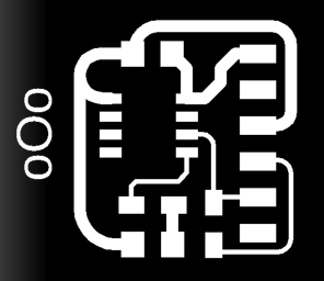
Identifying the pins of our chip used on the board is a little complicated. The IC has a number of physical pins, 1-8 in the ATtiny412. For the references of this microcontroller, we can find in HERE. However in the schematic from KiCAD shows theoretical number depending on what type of function and what function we want this pin to have in the circuit.
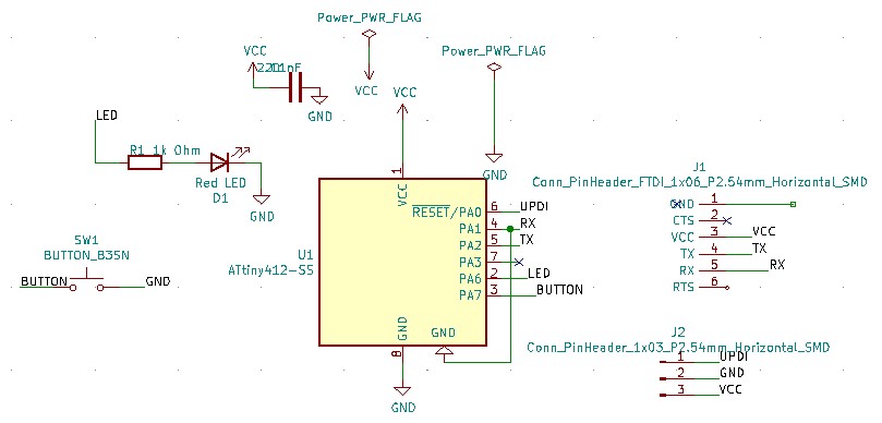
One for the UPDI device, which is connected to the ‘Hello’ board by the 3 pins connection. The other port has the FTDI serial communications device, which is also connected to the ‘Hello’ board by a 6 pins connection.
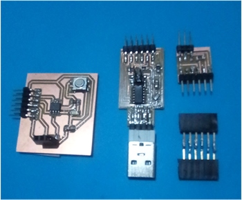
- my components for this week
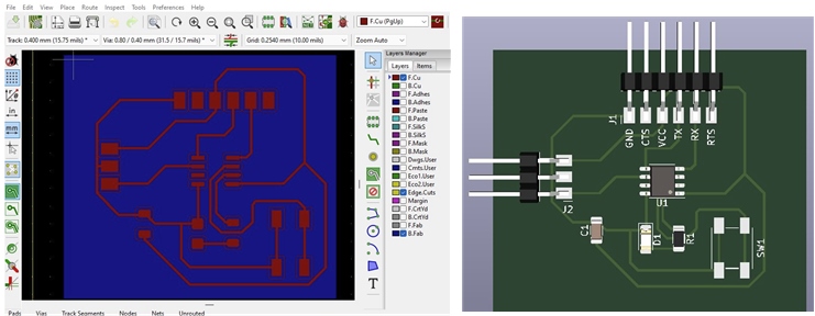
- Physical Layout Circuit Diagram from KiCAD
Create and Program A Sketch in The Arduino IDE
Arduino is an open-source hardware and software company, project and user community that designs and manufactures single-board microcontrollers and microcontroller kits for building digital devices.
Arduino board designs use a variety of microprocessors and controllers. The boards are equipped with sets of digital and analog input/output (I/O) pins that may be interfaced to various expansion boards (‘shields’) or breadboards (for prototyping) and other circuits.
Setting up the IDE for Our Boards
The boards feature serial communications interfaces, including Universal Serial Bus (USB) on some models, which are also used for loading programs. The microcontrollers can be programmed using the C and C++ programming languages, using a standard API which is also known as the “Arduino language”. In addition to using traditional compiler toolchains, the Arduino project provides an integrated development environment (IDE) and a command line tool (arduino-cli) developed in Go.
It is play important role to test our board we need a toolkit or development environment to set up UPDI programming toolkit with Arduino, Megatiny, and PyuPDI.

We can download the latest version of Arduino by Downloading ZIP files extract and putting them in the Applications folder.
When you program our boards we need to choose the programmer and the board. In the default Arduino installation we don’t have any ATtiny chips and this is reason why we need to install an add-on which called MegaTiny Core and in order to install that - find github repository megatinycore (by SpenceKonde) and from Installation page copy boards manager URL:
http://drazzy.com/package_drazzy.com_index.json
then,
copy it in Arduino Preferences - Additional Boards Manager URLs.
Then go to Tools-Boards Manager, it will load the lists and you should be able to find megaTinyCore, then hit install.
Go to Tools - Board and now you can see all these ATtiny chips. In my case I choose ATtiny412/[..].
Also make sure that Clock Speed is 20 MHz. Check that in Chip:ATtiny412 was selected as an ATtiny412 chip.
ATtiny412
All the programming info for the ATtiny we found here on Spencer his Github site, very helpful.
The 2 biggest differences in the ATtiny family is their memories and pins, found this little overview explaining it very well in the data sheet which thankfully is not that long, about 500 pages, so thankfull for the search function. On the right side its the internal mapping of the ATtiny, interesting to see and have an easy view of the possibilities.
Some compressed info:
8 pins
4 KB Flash Memory.
128 B EEPROM (electrically erasable programmable read-only memory)
256 B SRAM (static random-acces memory)
Max frequency 20 MHz.
Maximum voltage: 6V; minimum voltage -0.5 V.
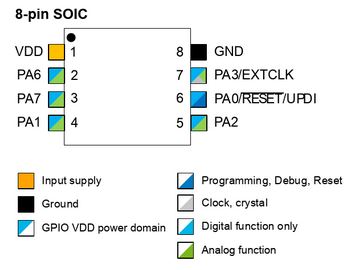
Pins of the micro controller:
VDD: Supply voltage.
GND: Ground.
Digital pins: PA0, PA1, PA2, PA3, PA4, PA5, PA6.
Analog pins: PA1, PA2, PA3, PA4, PA5, PA6.
UPDI Programming pin: PA0 (physical pin number 6).
External Clock Pin: PA3.
 .
.
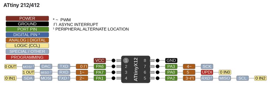
Within the communications section there are different types and their pins are different. Different communication protocols cannot all be used at the same time, because they have pins in common.
USART - Universal Synchronous and Asynchronous Receiver and Transmitter: It has the RX (PA1) and the TX (PA2).
SPI - Serial Peripheral Interface: It has only MOSI (PA1), MISO (PA2) and SCK (PA3).
TWI - Two Wire Interface (I2C): It has SDA (PA1) and SCL (PA2).
Another important thing that the data sheet is telling us is that you have to keep in mind which kind of input component you are using, digital or analog: for instance, if you are using a temperature sensor (analog component) you have to connect it to an ACD (analog to digital converter) port otherwise the micro controller isn’t able to transform the information that is receiving from the sensor to a digital data.
Multiplexed signals of ATTiny412 microcontroller can be identified from this table (PORT Function Multiplexing)
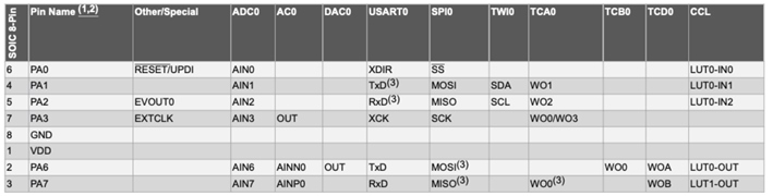
The information above is collected from the datasheet and several sites online, such as from ATtiny412_datasheet.
Below is the routing of our ATtiny412 as soldered on to the boards, with the RX on PA6 (pin4) and the TX on PA7 (pin5). But as you can read above the “normal” pins for RX is PA1 (pin11) and for the TX PA2 (pin12). More about this later.
Arduino IDE needs to be used for compile code and then another tool which is called pyupdi in order to upload it to the board, but in order to be able to find the compiled files you will need to edit configuration file.
Go to Arduino Preferences and there should be a link to the preferences file.
To edit this file, close Arduino software.
Open preferences.txt and what you need to add is build path like this command line
LEARNING ARDUINO
https://forum.arduino.cc/t/arduino-programming-cheat-sheet/67896
https://dlnmh9ip6v2uc.cloudfront.net/learn/materials/8/Arduino_Cheat_Sheet.pdf
Common Arduino Function
Materials
| Function | Value | Notes |
|---|---|---|
| pinMode(pin, mode) | pin: the Arduino pin number to set the mode of.mode: INPUT, OUTPUT, or INPUT_PULLUP | Configures the specified pin to behave either as an input or an output. |
| digitalRead(pin) | HIGH or LOW | Reads the value from a specified digital pin. |
| digitalWrite(pin,value) | HIGH or LOW | Write a HIGH or a LOW value to a digital pin. |
| AnaloglRead(pin) | pin | Maps input voltages between 0 and the operating voltage(5V or 3.3V) into integer values between 0 and 1023. The analog input pins can be used as digital pins, referred to as A0, A1, etc. |
| AnalogWrite(pin, value) | pin, 0 - 1023 | Writes an analog value (PWM wave) to a pin. After a call to analogWrite(), the pin will generate a steady rectangular wave of the specified duty cycle until the next call to analogWrite() (or a call to digitalRead() or digitalWrite()) on the same pin. |
| delay(value) | e.g. 1000 | Pauses the program for the amount of time (in milliseconds) specified as parameter. |
| map(value, from Low, from High, to Low, toHigh) | value, from Low, to High, to Low, to High | Re-maps a number from one range to another. That is, a value of from Low would get mapped to Low, a value of from High to High, values in-between to values in-between, etc. Returns the mapped value. |
| Serial.begin(speed) | baud rate | Sets the data rate in bits per second (baud) for serial data transmission. For communicating with Serial Monitor, make sure to use one of the baud rates listed in the menu at the bottom right corner of its screen. You can, however, specify other rates - for example, to communicate over pins 0 and 1 with a component that requires a particular baud rate. |
| Serial.end() | No value | Disables serial communication, allowing the RX and TX pins to be used for general input and output. |
| Serial.read() | No value | Reads incoming serial data. |
| Serial.println(value) | any ASCII character | Prints data to the serial port as human-readable ASCII text followed by a carriage return character (ASCII13, or ‘\r’) and a newline character (ASCII10, or ‘\n’). This command takes the same forms as Serial.print(). |
| Serial.swap(value) | Pin value | Swaps the Tx and Rx functionality of the pins. |
Code and Upload
With all that done we first tried Neils blinking program. From the datasheet of the AtTiny412 and our notes on the pins on our board. We found that the Led is connected to pin A6 (or also called 2), we thought that was quite confusing, but since we used the A-numbers on saturday with the arduino we thought we try that.
LED Blink
1st Coding
#include <avr/io.h>

#define LED_AVR PIN6_bm //PA3: LED pin

void setup() {
   PORTA.DIRSET = LED_AVR;
}

void loop() {
  PORTA.OUT |= LED_AVR;
  delay(1000);
  PORTA.OUT &= ~LED_AVR;
  delay(1000);
 }

 ```


### 2nd Coding


```py

#include <avr/io.h>

void setup() {
  // put your setup code here, to run once:
  PORTA.DIRSET=0xff;

}

void loop() {
  PORTA.OUT=0b01000000;
  delay(500);
  PORTA.OUT=0b00000000;
  delay(500);
  // put your main code here, to run repeatedly:

}
Test for Button
1st Coding for Button
#include <avr/io.h>

#define LED_AVR PIN6_bm //PA3: LED pin
#define BUTTON_AVR PIN7_bm //PA6: Button pin

void setup() {
/** Setup Instruction
  PORTA.DIRSET = PIN4_bm; // use PA4 as an output
  PORTA.DIRCLR = PIN4_bm; // use PA4 as an input
  or
  PORTA.OUTSET = PIN4_bm; // turn PA4 output on
  PORTA.OUTCLR = PIN4_bm; // turn PA4 output off
  or
  PORTA.OUTTGL = PIN4_bm; // toggle PA4 output
**/
   PORTA.DIRSET = LED_AVR;
   PORTA.DIRCLR = BUTTON_AVR;
}

void loop() {
/** HIGH/LOW Instruction
  PORTA.OUT |= PIN4_bm; // write PA4 high
  PORTA.OUT &= ~PIN4_bm; // write PA4 low
**/
  bool state = PORTA.IN & BUTTON_AVR; // read the state of a pin
  switch(state) {
    case 0:
    PORTA.OUT &= ~LED_AVR;
    break;
    case 1:
    PORTA.OUT |= LED_AVR;
    break;
    default:
    PORTA.OUT &= ~LED_AVR;
    break;
  }
 }
2nd Coding for Button
#include <avr/io.h>

void setup() {
   PORTA.DIRSET = 0b01000000;
   PORTA.DIRCLR = 0b10000000;
}

void loop() {
  bool state = PORTA.IN & 0b10000000; // read the state of a pin
  switch(state)
  {
    case 0:
    PORTA.OUT = 0b00000000;
    break;
    case 1:
    PORTA.OUT = 0b01000000;
    break;
    default:
    PORTA.OUT = 0b00000000;
    break;
  }
}
Our Results
With some programming experience behind me IDelved into ‘C’. working out what the syntax and structures were needed to create a working program. And how it related to the ATtiny IC chip.
Based on the different types of input/output and communication we would be needing in the future We wrote and verified the syntax for any problems.
- Testing for Blink UPDI HelloBoards
- Testing for Button_Blink_delay
Final Results
-
Having a light dimmed with input of a analog sensor.
-
Test button for on and off LED light with touching the button.
Learning Outcomes
After conducted the assignment, I got more information, knowledge, and experience in :
-
Identify relevant information in a microcontroller datasheet.
-
Implement programming protocols.
-
Coding and uploading a code to an embedded chip is all new for me, so a lot of learnings.
We notice that we are really at a loss when there is too many variables and we don’t know how to start (setting up the connections). Coding with arduino and C language seem very complex and looks a bit like Basic.