10. OUTPUT DEVICES
Output device is a piece of equipment/hardware which gives out the result of the entered input, once it is processed (into a physical machine-readable form for use with computerized or non-computerized equipment)
LEARNING PROCESS
Group Assignment
-
Measure the power consumption of an output device
-
Document our work to the group work page and reflect on our individual page what we learned
Group assignment can find in HERE
Individual Assignment
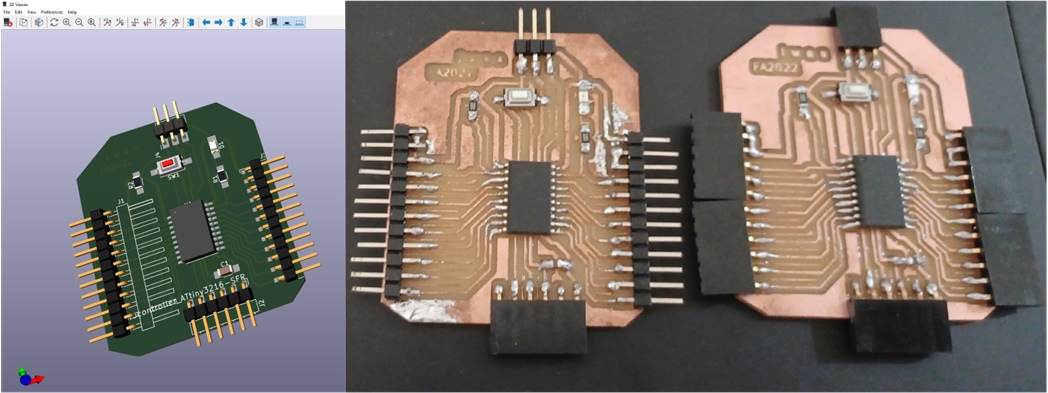
Add output devices to the Arduino UNO and my new microcontroller board (with ATtiny 3216) I’ve designed and programmed it to run the output devices in the form of a stepper motor actuator and a 20x4 LCD display.
Concept
An input device is something I connect to my board (with ATtiny 3216) that sends information into my board (with ATtiny 3216). An output device is something I connect to my board that has information sent to it.
The ideas were to continue with the board that I made for the input of Week_6 with an RGB LED output. Since that were some what of a failures, there were some serious improvements to be made that I could developed this further. See the updates to Week 10.
As I tried to redesign the board with a RGB LED and the corrections to make the the board work, I realised that there were some serious assemblies and programming going to be needed to get a reasonable output. Further trial activities which put into the sensor revelaed that synergized to the microcontroller. Something I was advised not to go near until the ‘Communications week’. Taking that into account, I needed to come up with a board to complete the assignment. So I came to the conclusion that I could still create a new board with a larger microcontroller (ATtiny3216, see the link below). The first board I made before (ATtiny412) need to upgrade with more pins due to requirement for some purposes.
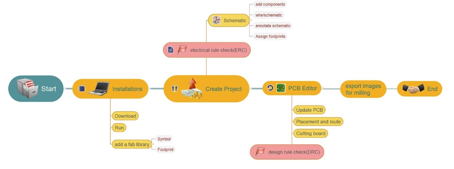
What I Did
- Working with Kicad6
First of all was to search for the relevant circuits that I could use as a starting point for my new board using ATtiny3216 (with KICAD 6.0). I have downloaded or cloned this software for Week 6 - Electronic Design from Fab_electronics_component_library for KiCad from fabcloud. I also can get it from repo_of_CBA and digikey-kicad-library is also useful.
 .
.
We can used this_link to install the library. After I cloned the repo, a folder kicad was created, then moved the folder to your KiCad library folder before I used it.
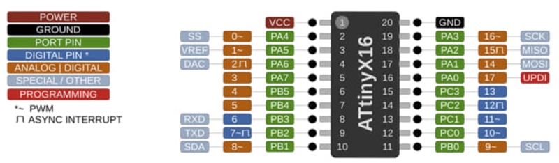
- Learning ATtiny3216 Datasheet
The ATtiny3216 series of microcontroller features the 8-bit AVR® processor with hardware multiplier. They run at up to 20 MHz and with up to 32 KB Flash with 2 KB SRAM and 256B of EEPROM in 20-pin packages. Thiese MCUs use the latest Core Independent Peripherals with low-power features. They include an Event System, intelligent analog and advanced peripherals. Capacitive touch interfaces with proximity sensing and driven shield are supported by the integrated QTouch® Peripheral Touch Controller (PTC).
- Start with Eeschema
To add and use the component, I opened .sch file. Eeschema, as a schematic editor, is used to add symbols. I can use hotkeys also by press Command + F1 key, hotkey list will show up.
| Hotkeys | Description |
|---|---|
| A | Add a new symbol to the sheet |
| R | Rotate |
| M | Move (wire will be disconnected) |
| G | Grab and more a symbol while keeping wires connected |
| L | Add a Label |
| W | Start drawing a Wire |
| V | Edit Value |
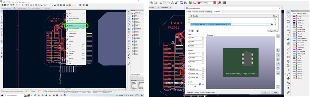
If we don’t find the symbol for the electronic component that will be used in the library list, I can download it by visiting the component provider’s site. One of them can be obtained from https://www.ultralibrarian.com/. https://www.ultralibrarian.com/.
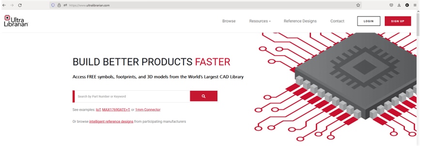
As in the example below I use it to find the 3D symbol for ATtiny3216.
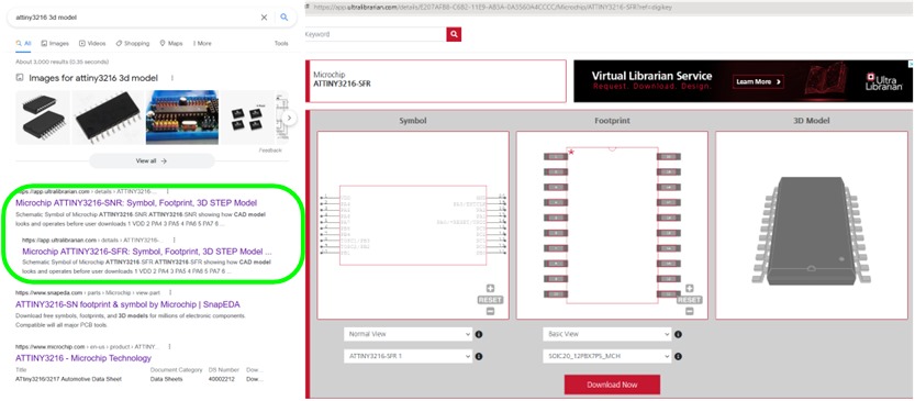
After I made sure the components I needed were complete and available in the Kicad6 library, I started designing the schematic of the components that should be on my board.
Positioning the components and connecting among them play important role before labelling. For example:
- connect the power flag with VCC, and also the another power flag with GND
- connect the resistor to the LED, do for other component
- add the value “V” of the component (resistor with 1k, 10k, capacitor with 1uF)
- etc.
if the number of connections is large, it would be better to use a label wire. We just need to label a connector, so if there is another connector with the same name, it will be automatically connected with the same label without having to make wires directly between components.
I put the name for pin on ATtiny 3216 with a label after created an extension wire for the label point. Press “L”, then give the name label, place to the point connector. Labeling must be consistent and the same name for the same junction, pay attention to uppercase and lowercase letters.
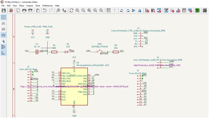
The components and their availability in the library are shown in the schematic editor in the image below.
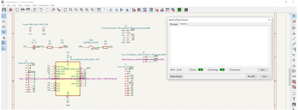
If all the components are in accordance with the schematic editor, I continue to evaluate their attachment to the electrical rules checker. Here all components used and connected must be appropriate and correct (no errors).
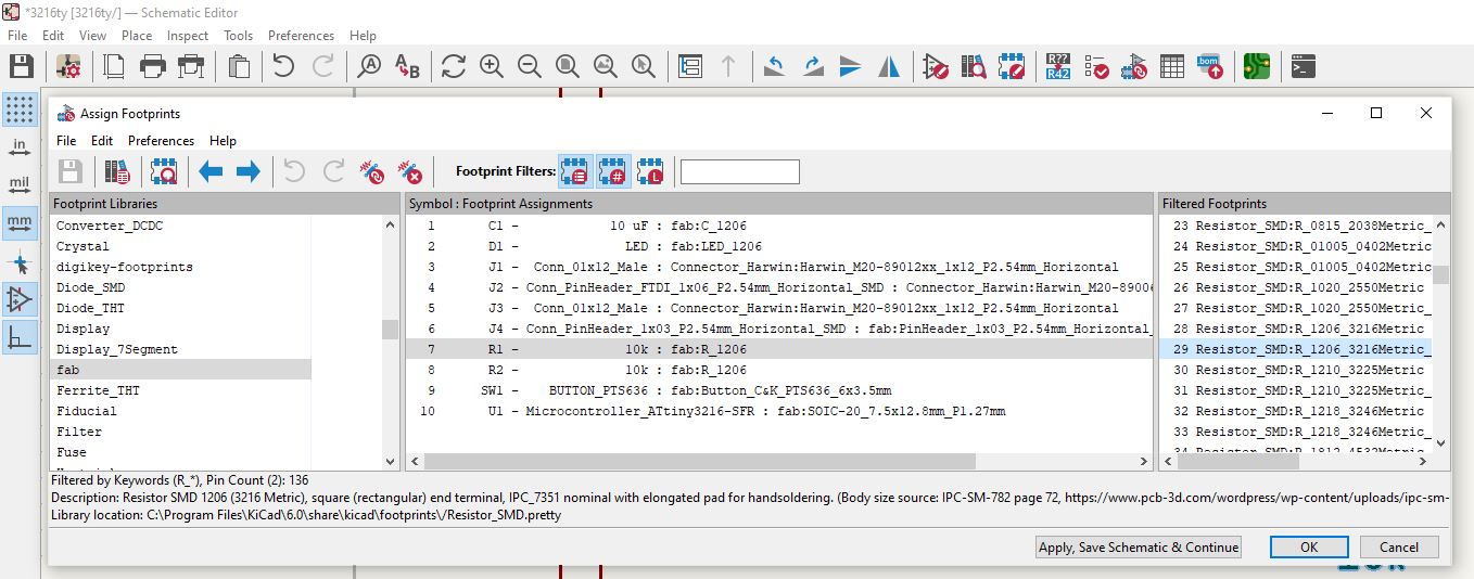
Footprint Assignment
I used footprint assignment to check the components and their connection before printed on the board. Footprints will usually be installed automatically if we have previously added the footprint library. I checked the shape of the footprint by load it automatically or manually.
Checking each component was conducted by choosing from the left box (source template footprint library), then we select the appropriate footprint shape in the right box. We can also see the footprint shape image from the footprint viewer menu.
If there is an error, I have to trace it and fix it because it will affect the connection in the design grooves on the PCB.
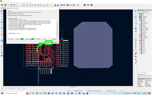
If the error is not found, I continue to update the PCB by selecting the Tools menu -> Update PCB from Schematic or by pressing the F8 key.
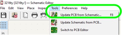
and then it showed to the image below.
In this section I connected between pins with connectivity rules. I created a route track based on the wire connection that has been made. The size of the track can be adjusted according to the board configuration that we entered earlier.
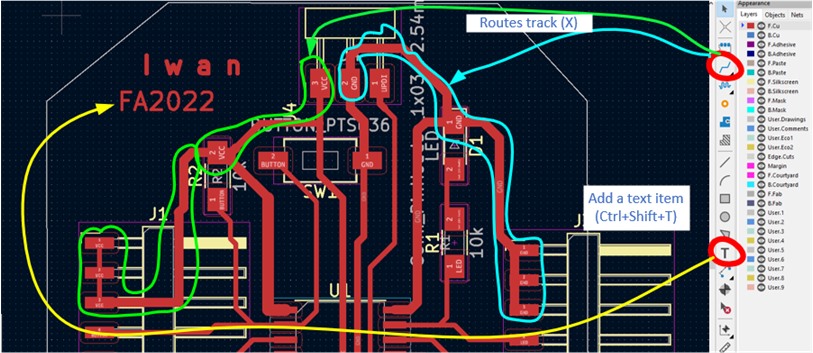
Usually for power lines (VCC, and GND), I used the lines larger (0.8 mm) while for data then used them 0.4 mm or 0.6 mm.
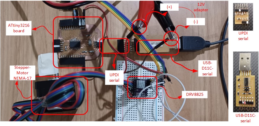
Next with my design board (attiny 3216), I used it for my output device task. In this assignment I used:
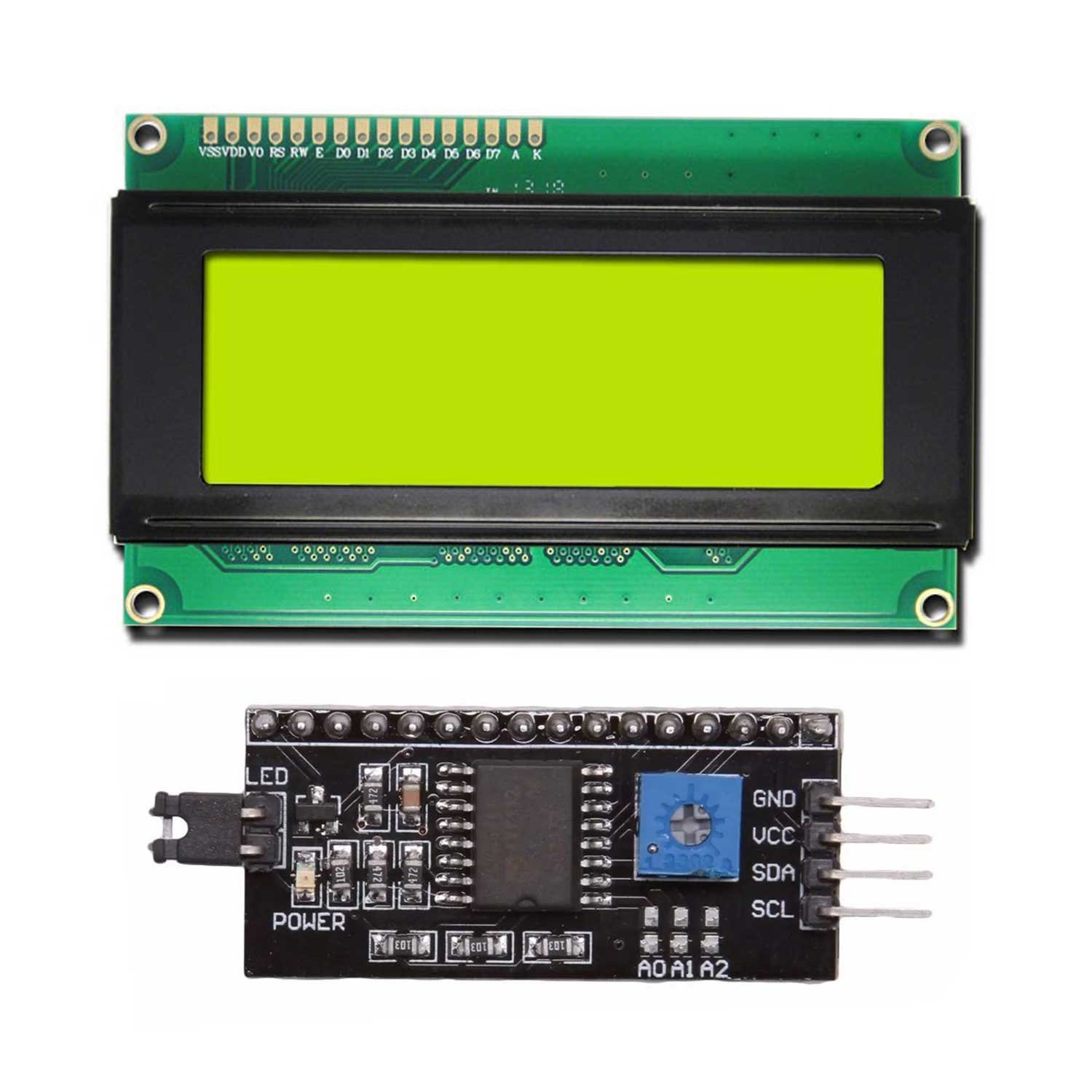
- LCD Display (with I2C Communication)
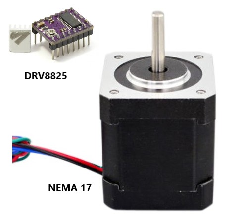
- Stepper Motor with DRV8825
Then I continued to integrate with some of input devices.
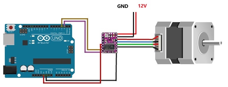
Working with Arduino and My3216 Board
I used Arduino Uno to ensure the program can be worked properly and then used and my board (Attiny 3216) following the code or instruction.
Motor Stepper Test
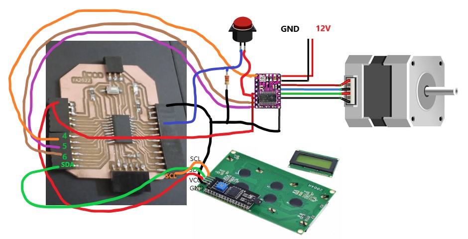
Integrated LCD and Motor Stepper
LEARNING PROCESS
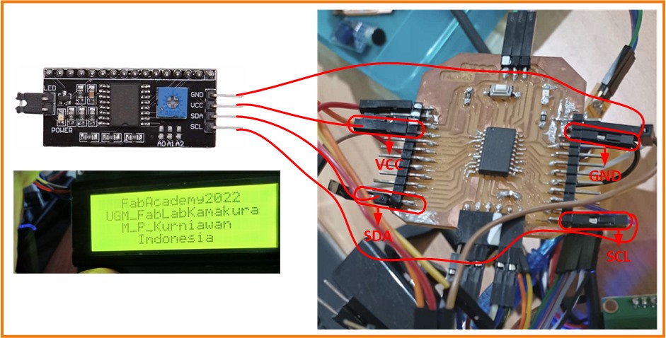
LCD Display
This LCD used I2C communication. The use of I2C communication will save the number of pins needed, but the pins used are already certain on the SDA, SCL pins.
In this assignment I used a 20 x 4 LCD Display and LiquidCrystal Library – as a device to show the output of the device.
I used Arduino language and reference from HERE herewith the output:
//Fab_Academy Assignment
#include <Wire.h>
#include <LiquidCrystal_I2C.h>

LiquidCrystal_I2C lcd(0x27,20,4);

void setup()
{
  lcd.init();                      // initialize the lcd
  lcd.init();
  // Print a message to the LCD.
  lcd.backlight();
  lcd.setCursor(3,0);
  lcd.print("FabAcademy2022");
  lcd.setCursor(1,1);
  lcd.print("UGM_FabLabKamakura");
   lcd.setCursor(3,2);
  lcd.print("M_P_Kurniawan");
   lcd.setCursor(5,3);
  lcd.print("Indonesia");
}


void loop()
{
}
 .
.
This is my I2C LCD display result:
Stepper Motor
#define dirPin 1
#define stepPin 0
#define stepsPerRevolution 200

void setup() {
  // Declare pins as output:
  pinMode(stepPin, OUTPUT);
  pinMode(dirPin, OUTPUT);
}

void loop() {
  // Set the spinning direction clockwise:
  digitalWrite(dirPin, HIGH);

  // Spin the stepper motor 1 revolution slowly:
  for (int i = 0; i < stepsPerRevolution; i++) {
    // These four lines result in 1 step:
    digitalWrite(stepPin, HIGH);
    delayMicroseconds(2000);
    digitalWrite(stepPin, LOW);
    delayMicroseconds(2000);
  }

  delay(1000);

  // Set the spinning direction counterclockwise:
  digitalWrite(dirPin, LOW);

  // Spin the stepper motor 1 revolution quickly:
  for (int i = 0; i < stepsPerRevolution; i++) {
    // These four lines result in 1 step:
    digitalWrite(stepPin, HIGH);
    delayMicroseconds(1000);
    digitalWrite(stepPin, LOW);
    delayMicroseconds(1000);
  }

  delay(1000);
My 3216board
Integrated circuit
#include  <LiquidCrystal_I2C.h>
LiquidCrystal_I2C lcd(0x27, 20,4);

int input1Pin = 8;
int BUTTONstate1 = 16;
int Index;
int StepEn = 6;
int StepStep = 5;
int StepDir = 4;
int step1 = 500

void setup()
{
 Serial.begin(9600); // this begins the serial connection with a baud rate of 9600
  lcd.begin();

  lcd.backlight();
  delay(250);
  lcd.noBacklight();
  delay(250);
  lcd.backlight();

  lcd.setCursor(0,0);
  lcd.print("Automatic Filling");
  lcd.setCursor(0,1);
  lcd.print("Beverages");
  delay(500);
  lcd.setCursor(0,2);
  lcd.print("Kamakaura - FA 2022");
  lcd.setCursor(0,3);
  lcd.print("Indonesia Student");
  delay(3000);
  lcd.clear(); //Then clean LCD

 pinMode(input1Pin, INPUT);
 pinMode(StepEn, OUTPUT); //Enable
 pinMode(StepStep, OUTPUT); //Step
 pinMode(StepDir, OUTPUT); //Direction

 digitalWrite(StepEn,LOW);

}
void loop()
{

  lcd.clear();
  lcd.setCursor(0,0);
  lcd.print("Choose your drink :");
  lcd.setCursor(0,1);
  lcd.print("1.Syrup");

  delay(1000);

BUTTONstate1 = digitalRead(input1Pin);

{
/* Button 1 : + - */
if (BUTTONstate1 == HIGH)
  {
    digitalWrite(StepDir,HIGH);
    lcd.clear();
    lcd.setCursor(0,1);
    lcd.print("Filling Chamber 1");
    lcd.setCursor(0,2);
    lcd.print("Syrop");
    for(Index = 0; Index < step1; Index++)
    {
      digitalWrite(StepStep,HIGH);
      delayMicroseconds(500);
      digitalWrite(StepStep,LOW);
      delayMicroseconds(500);
    }

  delay(1000);

    /* Goto initial*/
    digitalWrite(StepDir,LOW);
    for(Index = 0; Index < step1; Index++)
    {
      digitalWrite(StepStep,HIGH);
      delayMicroseconds(500);
      digitalWrite(StepStep,LOW);
      delayMicroseconds(500);
    }
  delay(500);
    lcd.clear();
    lcd.setCursor(0,1);
    lcd.print("Ready....!!");
  delay(1000);
  }
  else{
  }}
}
Test Result
Arduino-Stepper Motor Test
My 3216Board Stepper Motor Test
LEARNING OUTCOMES
After conducted this assignment I was be able to demonstrate workflows used in controlling an output device(s) with MCU board I have designed.