12. INPUT DEVICES
ASSIGNMENT
For this week’s assignment, I used two new boards with the ATtiny 3216. I spent a lot of time designing these boards due to my limited understanding of the relationships between electronic components and my limited soldering skills.
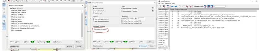
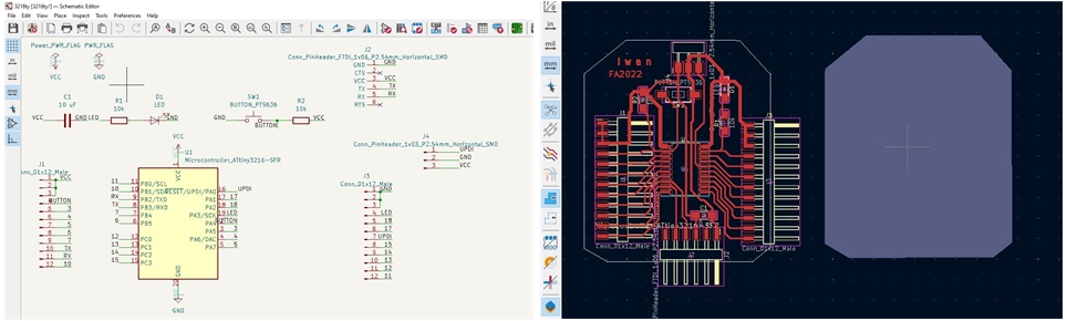
this is my board design for simulation
For the first board, I experienced many failures because of the problem of not connecting between components and after checking I finally found a solution by adding jumper cables to connect them.
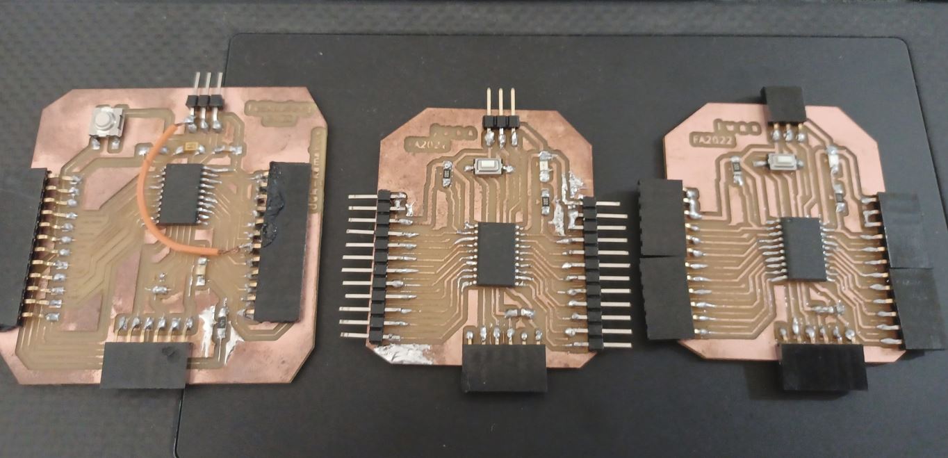
Since I am not satisfied with this result, I designed another board with the same microcontroller to improve its performance. And I managed to make both.
Group assignment:
-
Probe an input device(s)’s analog and digital signals
-
Document my work to the group work page and reflect on my individual page what I learned.
For group assignment you can find in HERE.
Individual assignment:
- Measure temperature and alcohol (gas): add sensors to a microcontroller board that I have designed and read them.
Learning Process
-
Linked to the group assignment page.
-
Documented what I learned from interfacing an input device(s) to microcontroller and how the physical property relates to the measured results.
Working with pH sensor, temperature sensor, and MQ3 alcohol sensor
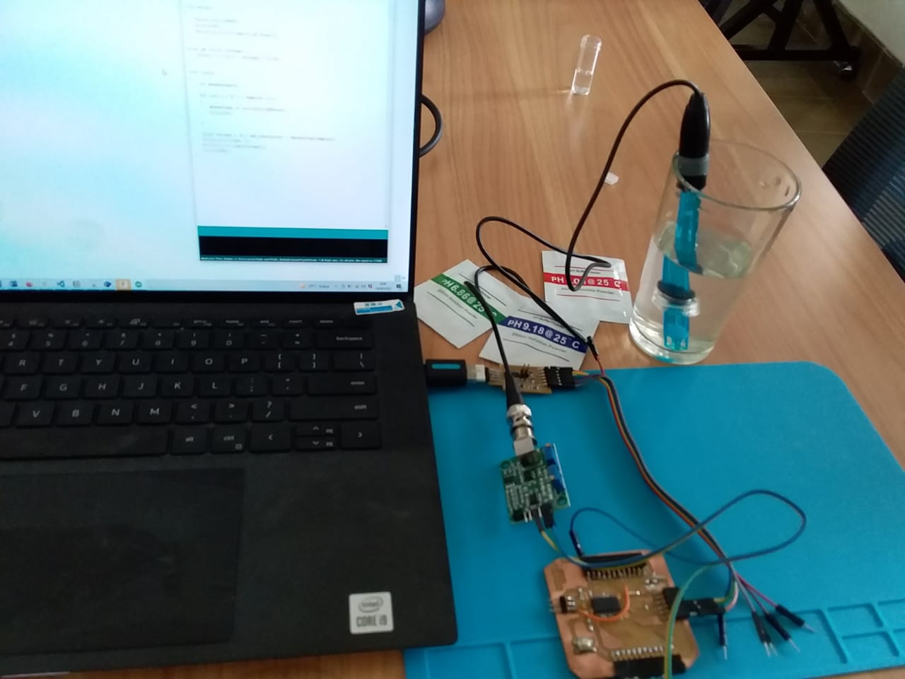
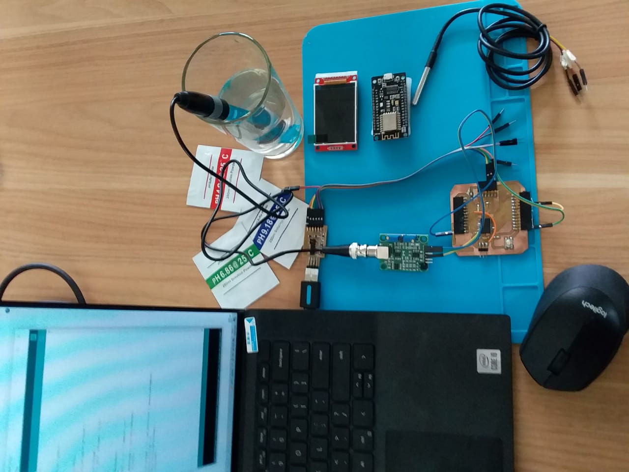
I have started this week’s assignment using the pH sensor as the initiation of Final Project activities. However, until now there are still problems in identifying the precision of the electrical conductivity value.
 .
.
This value is important as the electrode design scheme ensures an environment with the constant binding of H+ ions on the inside of the glass membrane.
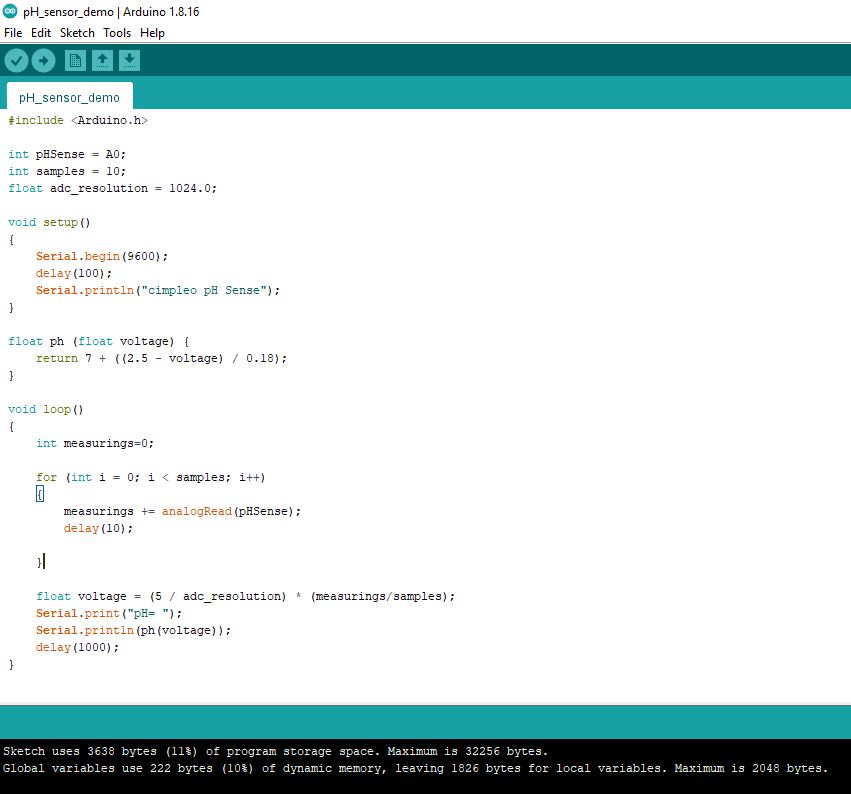
After successful hardware connections, I started for programming my board (with ATtiny3216).
 .
.
When the probe is dipped into the solution to be tested, hydrogen ions in the test solution start exchanging with other positively charged ions on the glass membrane, which creates an electrochemical potential across the membrane which is fed to the electronic amplifier module which measures the potential between both electrodes and converts it to pH units.
I didn’t continue because there was a need for adjustments to the BMC connector for pH electrtode which I would work on in the final project.
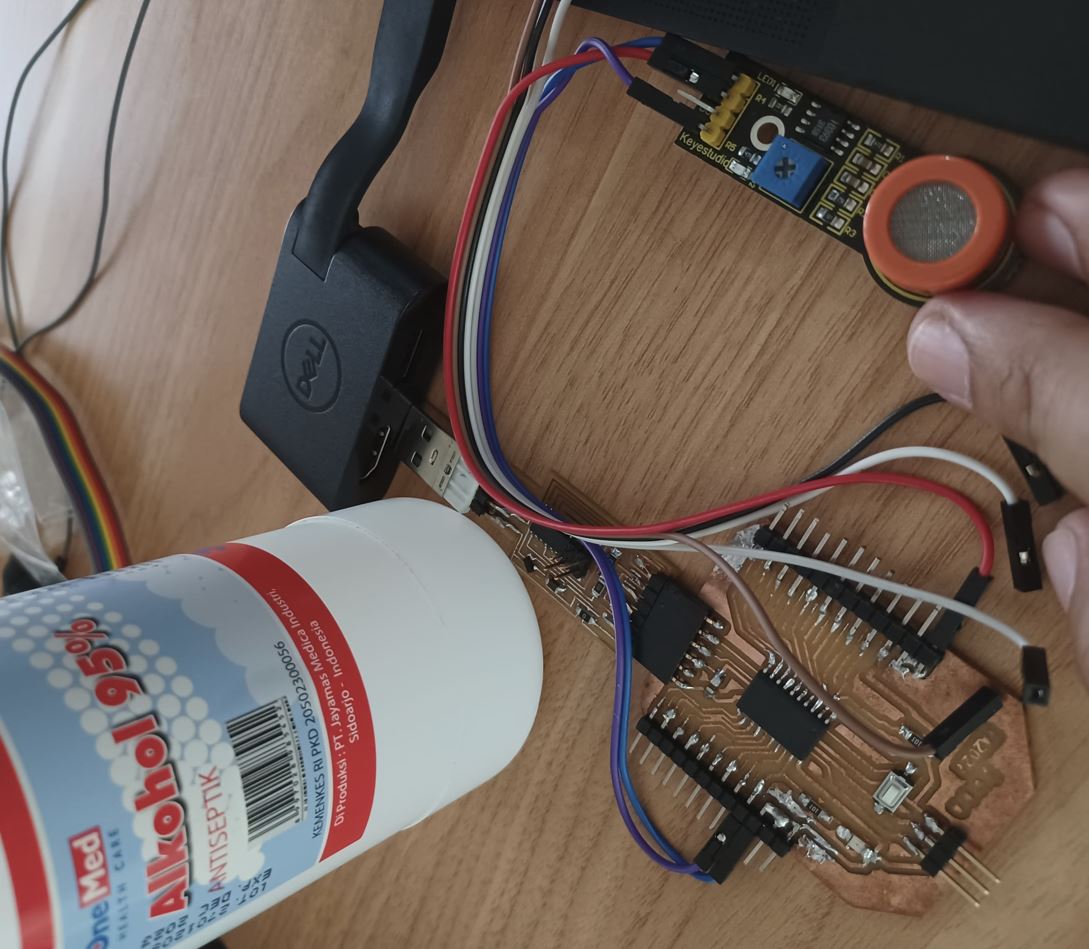
In this assignment, I used MQ3 sensors, which type of Metal Oxide Semiconductor (MOS)/Chemiresistors, to indicate the change of resistance of the sensing material when exposed to alcohol. I chose this parameter due to related with the object of my final product (fresh milk). Then, by placing it in a simple voltage divider network, I tried to detect the volatile alcohol. MQ3 alcohol sensor works on 5V DC and draws around 800mW. It can detect Alcohol concentrations anywhere from 25 to 500 ppm.
!!! Just info:
When measuring gases, the term concentration is used to describe the amount of gas by volume in the air. The two most common units of measurement are parts-per-million, and percent concentration.
Parts-per-million (abbreviated ppm) is the ratio of one gas to another. For example, 500ppm of alcohol means that if you could count a million gas molecules, 500 of them would be of alcohol and 999500 molecules would be some other gases.
Here are the general information about the sensor:
| Specification | Description |
|---|---|
| Operating voltage | 5V |
| Heater resistance | 33Ω ± 5% |
| Heating consumption | <800mw |
| Sensing Resistance | 1 MΩ – 8 MΩ |
| Concentration Scope | 25 – 500 ppm |
| Preheat Time | Over 24 hour |
How MQ3 Alcohol Sensor Works?
When SnO2 semiconductor layer is heated at high temperature, oxygen is adsorbed on the surface. In clean air, electrons from the conduction band in tin dioxide are attracted to oxygen molecules. This form an electron depletion layer just below the surface of SnO2 particles and forms a potential barrier. As a result, the SnO2 film becomes highly resistive and prevents electric current flow.
In the presence of alcohol, however, the surface density of adsorbed oxygen decreases as it reacts with the alcohols; which lowers the potential barrier. Electrons are then released into the tin dioxide, allowing current to flow freely through the sensor.
MQ3 Alcohol Sensor Module Hardware Overview
The analog output voltage provided by the sensor (at 15 pin) varies in proportion to the alcohol concentration. The higher the alcohol concentration in the air, the higher the output voltage; Whereas lower concentration gives lower output voltage. The following animation shows the relationship between alcohol concentration and output voltage.
The module has a built-in potentiometer for adjusting the sensitivity of the digital output (DO). I used it to set a threshold; so that when the alcohol concentration exceeds the threshold value, the module will output LOW otherwise HIGH.
I have been trying callibrate them to trigger an action when certain threshold is reached. For example, when the alcohol concentration in expired milk exceed a threshold, I can tell the quality of milk is decreased (harmful).
MQ3 Alcohol Sensor Module Pinout
For_mq-3_sensor_module
| Pin Name | Description |
|---|---|
| VCC | This pin powers the module, typically the operating voltage is 5V |
| GND | Used to connect the module to system ground |
| Digital Out (DO) | We can also use this sensor to get digital output from this pin, by setting a threshold value using the potentiometer |
| Analog Out (AO) | This pin outputs 0 - 5V analog voltage on the intyensity of the gas |
For_mq-3_sensor
| No. | Pins | Description |
|---|---|---|
| 1 | H | Out of the two H pins, one pin is connected to supply and the other to ground |
| 2 | A | The A pins and B pins are interchange. These pins will be tied to supply voltage. |
| 3 | B | The A pins and B pins are interchange. One pin will act as output while the other will be pulled to ground. |
Voltage_divider_calculation
I defined the concentration of a gas in part per million (ppm) according to the resistance ratio of the sensor (with variable notation RS/R0). In this calculation, RS is the resistance of the sensor that changes depending on the concentration of gas, and R0 is the resistance of the sensor at a known concentration without the presence of other gases, or in fresh air. I derived a formula to find RS using Ohm’s Law:
V = I x R
Where V is voltage, I is current, and R is resistance. In this case, RS, which is the resistor between pins A and B, and RL are in series. Thus, I can simplify the circuit as shown below:
From Ohm’s Law, we can derive I as follows:
I = V / R
Which in our circuit is equal to:
I = VC / (RS+RL)
I can obtain the output voltage at the load resistor using the value obtained for I and Ohm’s Law.
V = I x R
VRL = [VC / (RS + RL)] x RL
VRL = (VC x RL) / (RS + RL)
So, I can calculate RS:
VRL x (RS + RL) = VC x RL
(VRL x RS) + (VRL x RL) = VC x RL
(VRL x RS) = (VC x RL) - (VRL x RL)
RS = [(VC x RL) - (VRL x RL)] / VRL
RS = [(VC x RL) / VRL] - RL
This formula will help to find the values of the sensor resistance for different gases.
To calculate R0, I need to find the value of the RS in fresh air. This will be done by taking the analog average readings from the sensor and converting it to voltage. Then we will use the RS formula to find R0.
On the gas sensor modules this is part of a voltage divider formed by the internal element of each gas sensor and potentiometer R3 (Set Point). The output of this voltage divider is fed into the non-inverting inputs of the two op-amps on the LT1013 dual op-amp IC. Op-amp A is configured as a buffer with unity gain and is used to provide a non-loaded test point for the signal voltage at TP1 (+) and TP2 (-).
The signal voltage is also being fed into op-amp B which is configured as a comparator that gets its reference voltage at the inverting input from potentiometer R4 (Trip Level) and is also available at TP3 (+) and TP4 (-). The output of op-amp B goes out to the ALR pin through a 1 kΩ resistor providing a TTL-compatible signal to a microcontroller. This output also connects to a green LED on the gas sensor modules.
Measuring_alcohol_concentration_using_analog_output
As you know that the module provides both analog and digital output, so for our first experiment we will measure the alcohol concentration by reading the analog output.
#define MQ3pin 15

float sensorValue;  //variable to store sensor value

void setup() {
  Serial.begin(9600); // sets the serial port to 9600
  Serial.println("MQ3 warming up!");
  delay(20000); // allow the MQ3 to warm up
}

void loop() {
  sensorValue = analogRead(MQ3pin); // read analog input pin 0

  Serial.print("Sensor Value: ");
  Serial.println(sensorValue);

  delay(2000); // wait 2s for next reading
}
Wiring
Let’s hook the MQ3 alcohol sensor up to the my board (with ATtiny3216).
Start by connecting VCC pin to the 5V pin on my board and connect GND pin to the Ground pin on my board (with ATtiny3216). Finally, connect AO output pin on the module to Analog pin 15 on the my board (with ATtiny3216).
The following illustration shows the wiring.
KY-013 Analog Temperature Sensor
The KY-013 Analog Temperature Sensor module can measure ambient temperature based on the resistance of the thermistor on the board. This module consist of a NTC thermistor, a 10 kΩ resistor, and 3 male header pins. The thermistor resistance varies according to its surrounding temperature. The value of resistance can be used to calculate the actual temperature.
Connection Diagram
Connect module power line (middle) and ground (-) to 5V and GND on the Arduino respectively. Connect the module signal pin (S) to pin 15 on the Arduino.Some KY-013 have a different pin arrangement. Please check your board before connecting.
 .
.
KY-013 Code
The following coding sketch will derive the temperature from the thermistor using the Steinhart-Hart equation. The code will return temperature in Celcius, uncomment line 17 to get temperature in farenheit.
int ThermistorPin = A0;
int Vo;
float R1 = 10000; // value of R1 on board
float logR2, R2, T;
float c1 = 0.001129148, c2 = 0.000234125, c3 = 0.0000000876741; //steinhart-hart coeficients for thermistor
void setup() {
  Serial.begin(9600);
}
void loop() {
  Vo = analogRead(ThermistorPin);
  R2 = R1 * (1023.0 / (float)Vo - 1.0); //calculate resistance on thermistor
  logR2 = log(R2);
  T = (1.0 / (c1 + c2*logR2 + c3*logR2*logR2*logR2)); // temperature in Kelvin
  T = T - 273.15; //convert Kelvin to Celcius
 // T = (T * 9.0)/ 5.0 + 32.0; //convert Celcius to Farenheit
  Serial.print("Temperature: ");
  Serial.print(T);
  Serial.println(" C");
  delay(500);
}
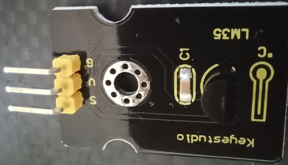
LM35 Temperature Sensor
The LM35 is a low voltage, precision centigrade temperature sensor manufactured by Texas Instruments. It is a chip that provides a voltage output that is linearly proportional to the temperature in °C and is, therefore, very easy to use with my board.
The LM35 temperature sensor is fairly precise, never wears out, works under many environmental conditions and requires no external components to work. In addition, the LM35 sensor does not require calibration and provides a typical accuracy of ±0.5°C at room temperature and ±1°C over a full −55°C to +155°C temperature range.
The sensor can be powered with a 4V to 30V power supply and consumes less than 60µA during active temperature conversions, providing very low self-heating (less than 0.08°C in still air).
Here are the general information about the sensor:
| Specification | Description |
|---|---|
| Power supply | 4V to 30V |
| Current draw | 60µA |
| Temperature range | −55°C to +155°C |
| Accuracy | ±0.5°C |
| Concentration Scope | Output scale factor |
| Output at 25°C | 250mV |
Working Principle
The LM35 uses a solid-state technique to measure the temperature. It makes use of the fact that the voltage drop between the base and emitter (forward voltage – Vbe) of the Diode-connected transistor decreases at a known rate as the temperature increases. By precisely amplifying this voltage change, it is easy to generate an analog signal that is directly proportional to temperature.
This linear relationship between forward voltage and temperature is the reason why diode-connected transistors are used as temperature measurement devices. Essentially this is how temperature is measured, although there have been some improvements in this technique over the years.
Testing the LM35 Sensor
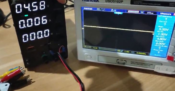
Testing the LM35 is pretty easy, just connect the left pin to 4V to 30V power supply (Four AA batteries work great) and the right pin to ground (assuming the flat side of the sensor is facing me). Now connect your multimeter in DC voltage mode to ground and the middle pin. At the room temperature (25°C), the voltage should be about 0.25V. Try squeezing the plastic case of the sensor gently to see a rise in temperature.
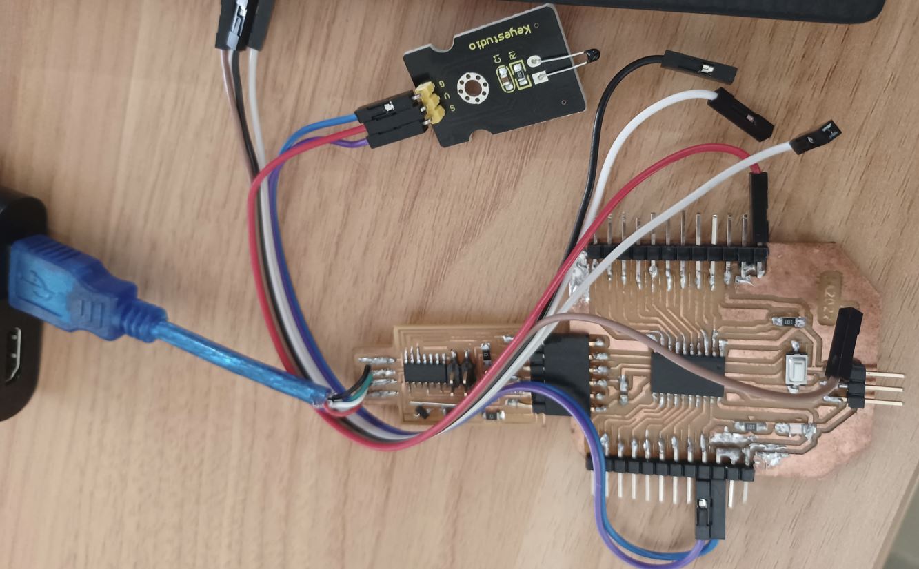
Connecting the LM35 Temperature Sensor to my board (with ATtiny3216)
By hooking up the LM35 to my board, we need to connect three pins: two for power and one for reading the sensor value. The sensor can be powered from 5V. The positive voltage connects to ‘+Vs’ and ground connects to ‘GND‘. The middle pin ‘Vout’ is the analog signal output from the sensor and connects to the A0 analog input of my board (with ATtiny3216).
Below is the hookup for the experiments with the LM35:
Reading the Analog Temperature Data
As you can see in the wiring diagram above, the output of the LM35 is connected to one of the analog inputs of my board. The value of this analog input can be read with the analogRead() function.
However, the analogRead() function does not actually return the output voltage of the sensor. Instead it maps the input voltage between 0 and the ADC reference voltage (technically it is the operating voltage i.e. 5V or 3.3V ) to 10-bit integer values ranging from 0 to 1023. To convert this value back to the sensor’s output voltage, use this formula:
Vout = (reading from ADC) * (5 / 1024)
This formula converts the number 0-1023 from the ADC into 0-5V
Then, to convert volts into temperature, use this formula:
Temperature (°C) = Vout * 100
Coding for – Simple Thermometer
The following sketch shows a quick way to read LM35 temperature sensor and can serve as the basis for more practical experiments and projects. It simply reads the value from the LM35 using analog port A0 and prints the current temperature (in both °C and °F) on the serial monitor. Go ahead and upload it to my board.
// Define the analog pin, the LM35's Vout pin is connected to
#define sensorPin 15

void setup() {
  // Begin serial communication at 9600 baud rate
  Serial.begin(9600);
}

void loop() {
  // Get the voltage reading from the LM35
  int reading = analogRead(sensorPin);

  // Convert that reading into voltage
  float voltage = reading * (7.82 / 1024.0);

  // Convert the voltage into the temperature in Celsius
  float temperatureC = voltage * 100;

  // Print the temperature in Celsius
  Serial.print("Temperature: ");
  Serial.print(temperatureC);
  Serial.print("\xC2\xB0"); // shows degree symbol
  Serial.print("C  |  ");

  // Print the temperature in Fahrenheit
  float temperatureF = (temperatureC * 9.0 / 5.0) + 32.0;
  Serial.print(temperatureF);
  Serial.print("\xC2\xB0"); // shows degree symbol
  Serial.println("F");

  delay(1000); // wait a second between readings
}
Learning outcomes
After Conducted this assignment, we are be able to demonstrate workflows used in sensing something with input device(s) and MCU board. For MQ3 Alcohol sensor, the sensitive material used for this sensor is SnO2, whose conductivity is lower in clean air. It’s conductivity increases as the concentration of alcohol gases increases. It has high sensitivity to alcohol and has a good resistance to disturbances due to smoke, vapor and gasoline.
This module provides both digital and analog outputs. MQ3 alcohol sensor module can be easily interfaced with my board with ATtiny3216.
This alcohol sensor is suitable for detecting alcohol concentration on your breath, just like your common breathalyzer. It has a high sensitivity and fast response time. Sensor provides an analog resistive output based on alcohol concentration. The drive circuit is simple, with one resistor, the interface could be a 0-3.3V ADC.
Calibrating Sensors
Based on LM35 precision centrigrade temperature sensors data sheet, this deviceF does not require any external calibration or trimming to provide typical accurates of ~0.75oC over a full ~55oC to 150oC temperature range. Lower cost is assured by trimming and ca;libration at the water level.
Calibrating process can be conducted by figuring out what voltages correspond with what temperatures. Just measure the temperatue with a different thermometer and see what the corresponding voltage is. I can do this at several different temperatures and graph the voltage vs the temperature measured, then throw on a trendline and display the equation. This equation should work to convert the voltage readings to temperature. Just plug in my voltage reading for X.
For MQ3 alcohol sensor, according to (trybotics.com), it’s really hard to calibrate this sensor for even an approximate BAC reading. It’s even difficult to correlate readings to looked-up BAC values. There are many environmental factors that affect the resistance within the sensor (humidity, temperature, oxygen concentration), and this is only a $5 device anyway. And as evidenced by the lack of consistency between online BAC calculators, there’s not even concensus about how to compute BAC. Law enforcement agencies have much more sophisticated breathalyzers, and often rely on actual blood tests or urinalysis for evidence.
Important Files
References
-
http://academy.cba.mit.edu/classes/input_devices/index.html.
-
http://fablabkamakura.fabcloud.io/FabAcademy/local-sessions/week9/.
-
https://lastminuteengineers.com/lm35-temperature-sensor-arduino-tutorial/.
-
https://lastminuteengineers.com/mq3-alcohol-sensor-arduino-tutorial/.