5. 3D SCANNING AND PRINTING
# 5. 3D SCANNING AND PRINTING
Reverse engineering is a powerful way to create digital designs from a physical part, and can be a valuable tool in your prototyping toolkit alongside technologies like 3D scanning and 3D printing.
Weekly Assignment Requirements
In this assignment,I walked walk through the step-by-step reverse engineering process for an aftermarket digital gauge and explain how to scan a part for 3D printing, with tips along the way for using the right reverse engineering tools, from CAD software to to 3D scanners and 3D printers.
Group assignment:
-
Test the design rules for your 3D printer(s)
-
Document your work and explain what are the limits of your printer(s) (in a group or individually)
-
Document your work to the group work page and reflect on your individual page what you learned
Individual assignment:
-
Design and 3D print an object (small, few cm3, limited by printer time) that could not be easily made subtractively.
-
3D scan an object, try to prepare it for printing (and optionally print it)
Learning Process
Have you answered these questions?
- Linked to the group assignment page
- Explained what we learned from testing the 3D printers
- Documented how we designed and made our object and explained why it could not be easily made subtractively
- Documented how we scanned and prepared an object (for 3D printing)
- Included your original design files for 3D printing (both CAD and common format for 3D printing) and hero shots
What I’ve done this week
Group assignment:
Find Group Assignment HERE
Individual assignment:
3D Scanning Process
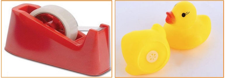
For individual assignment in this week’s assignment I conducted 3D scanning process for Scotch Tape Dispenser and rubber duck toy using Fixed scanning.
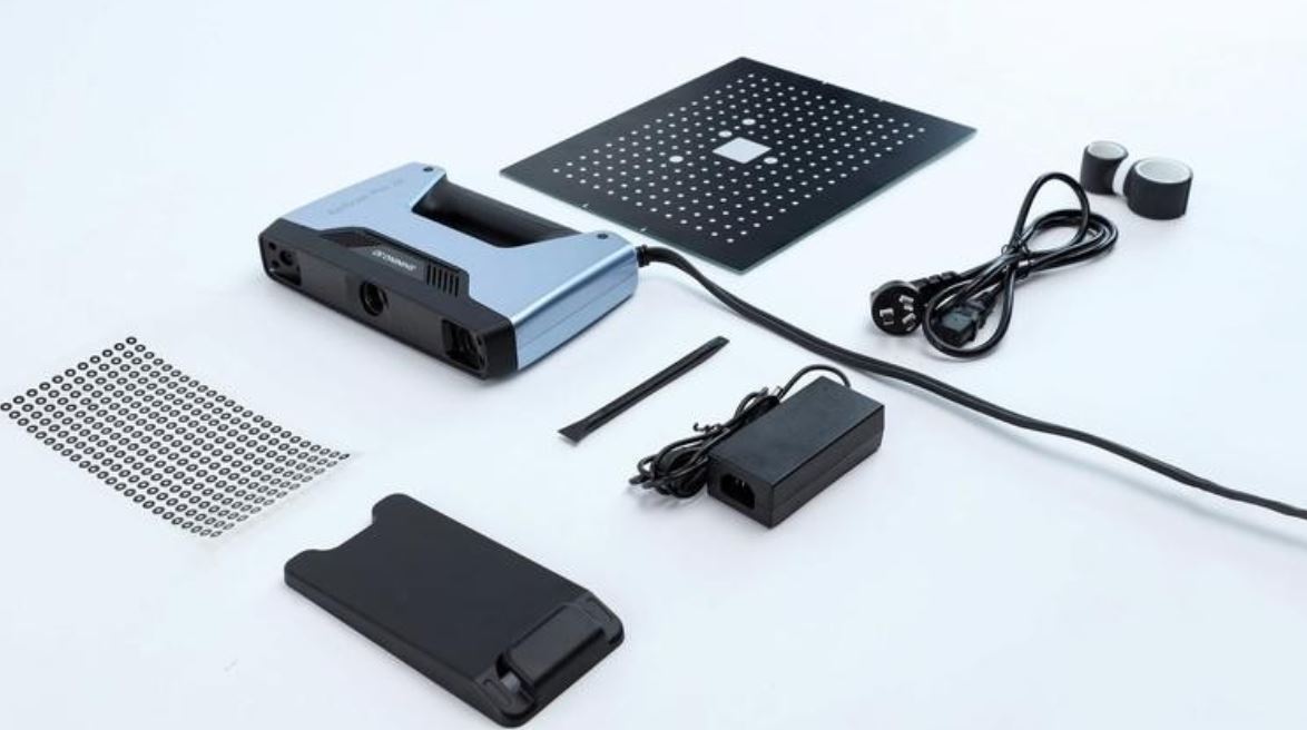
I used EinScan Pro 2X Handheld Scanner 2020 Series and its rotary table, and also 3.6 EXScan Pro Software. 3D scanners measure complex objects very quickly, and can speed up our design workflow tremendously when real-life references are involved.
One of the biggest challenges when converting physical objects to digital is a major incompatibility between two different types of 3D models: meshes and solids.
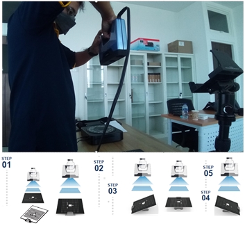
- Set up the devices
- Calibrate the Devices
I have to follow a calibration procedure before running this machine. From this procedure, how to get accurate scanning process will be obtained.
My Object for Scanning Process
To scan the object, I put my object on the rotating table. Then running the ExScan software :
- select Fix Scan,
- new project,
- non texture scan,
- positioning the scan marker to the center of object
3D Scan the Object
Plastic_tape_dispenser
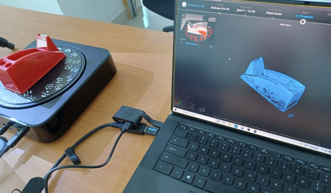
before scan the object, I had to determine the object position, and align the distance, and brightness correctly.

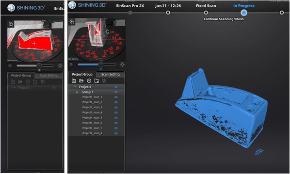
When scan options with a rotary table was selected, it rotated 8 times to capture the object which we can see in the top-left preview screen.
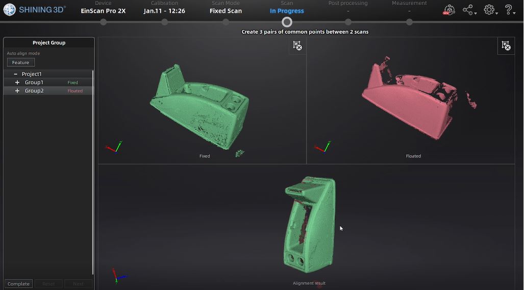
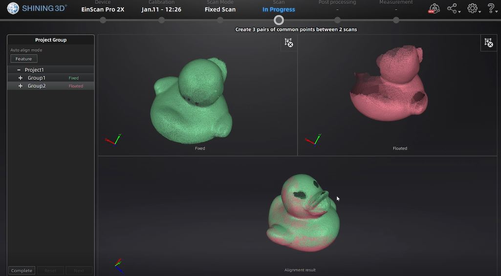
After scanning process, aligning and meshing process was conducted to create 3 pairs of common points between 2 scans. The matching shape will be selected.
This picture above is the result of my first scanning process.
I will continue for my second object.
Duck_rubber_toy
In the same way, I did a scan for rubber ducks.
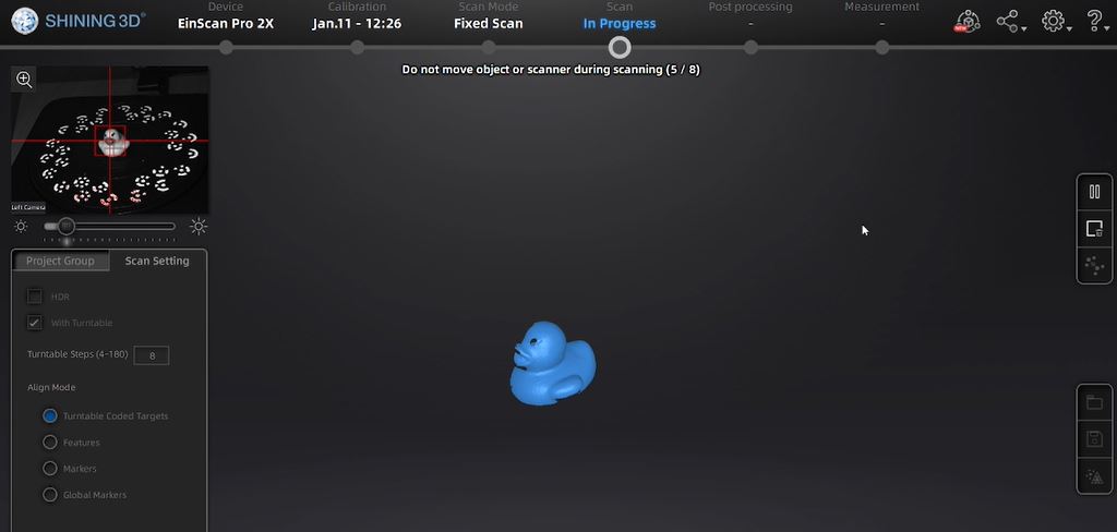
I placed the object on the rotary table by determining the accuracy of the object that can be seen in the preview section on the top left of 3.6 EXScan Pro Software.
After the canning process is complete, I continued with the aligning and meshing stages.
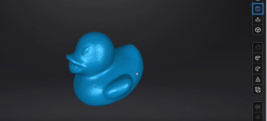
I got the process result as I wanted.
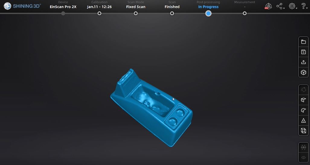
3D Scan Results
My_roller_tape_case
My_little_duck
3D scanning is helpful for reverse engineering, analysis, designing and measuring complex curved surfaces, quality monitoring, prototyping, development of industrial tools and many more.
These assignments lead us to learn advanced software for accurate measurement, storage, analysis, which helps increase the process’s flexibility and reliability.
3D Printing Process
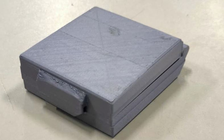
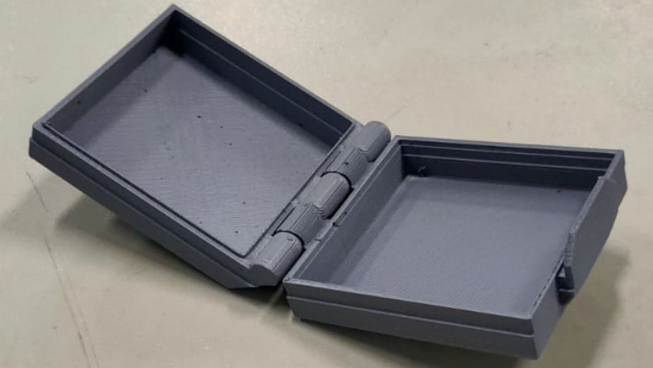
In this assigment, I learnt Additive Manufacturing as process by adding small layers which are combined to produce latch box. I used Fusion360 for 3D design which provides information to the printer about the shape and layers to be made.
With the ability to capture and modify physical shapes, I can design 3D printed parts that fit perfectly on existing products of all kinds. 3D printed jigs allow us to repeatedly locate a drill or saw, or assemble parts precisely with adhesive. Create close-fitting, reusable masks for sandblasting, painting, or etching.
Design_process
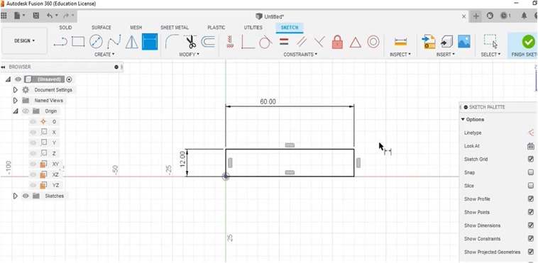
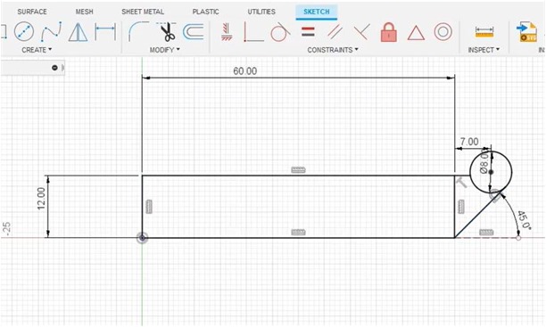
I started with a sketch of the shape by increasing the size of each side/area to construct the dimensions of latch-box.
Next, I made circle shape to determine how big the arc is to anchor the closing hinges.
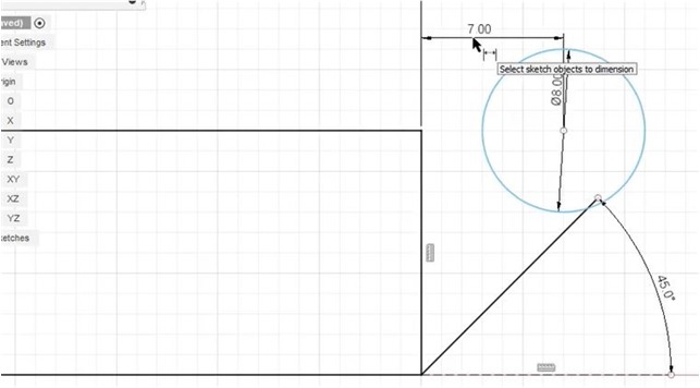
I used a 45 degree angle for the hinge support that was anchored on one of the high sides.
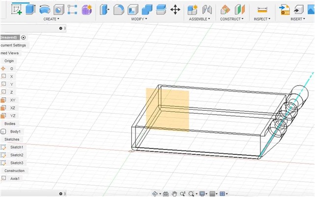
I did the extruding process to give a clearer picture of the design that was made.
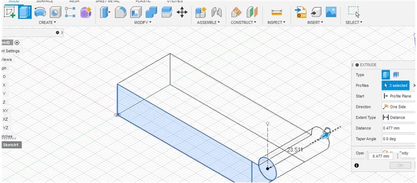
The stand is clearly visible on one side for immediate alignment with the connected part of the cover (top side)
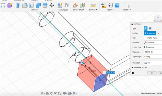
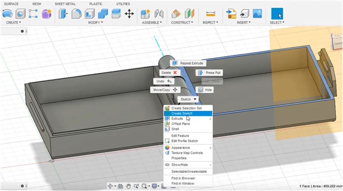
I use the “Offset Plane” to define a flat plane to use for sketching and as a reference to run the mirror plane feature to duplicate the hinge with a smaller size.
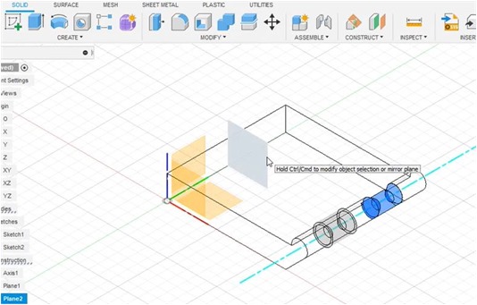
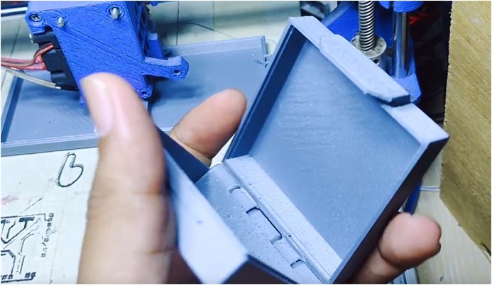
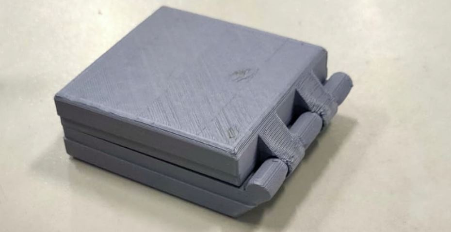
Small hinge sizes are used for connecting and latching the top and bottom of the box.
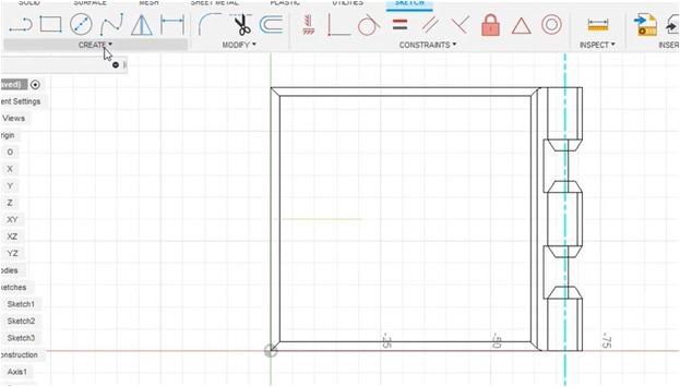
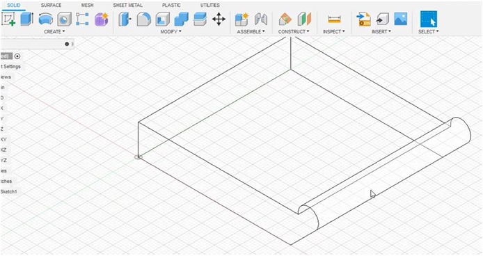
In general, a sketch of the latch box is shown in the image below.
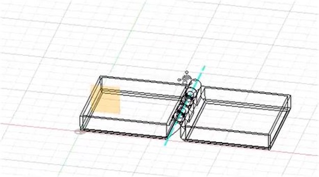
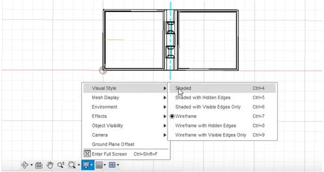
Furthermore, to analyze the manufacturing process, identification of shaded with hidden edges is done by using the visual style tab.
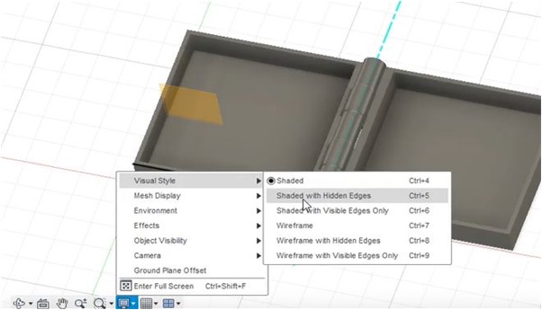
Furthermore, the design is arranged as follows.
The following is a 3D schematic visualized in 3D paint.
3D Printing Process
When I first tried to use a 3D printer, the problem I experienced was that the filament didn’t stick to the hot plate/plane even though it came out of the nozzle in perfect condition. Next I stopped the printing process and calibrated for the xyz coordinates. I have Ultimaker Cura and PrusaSlicer 2.4.2 installed. on my laptop.
Printer
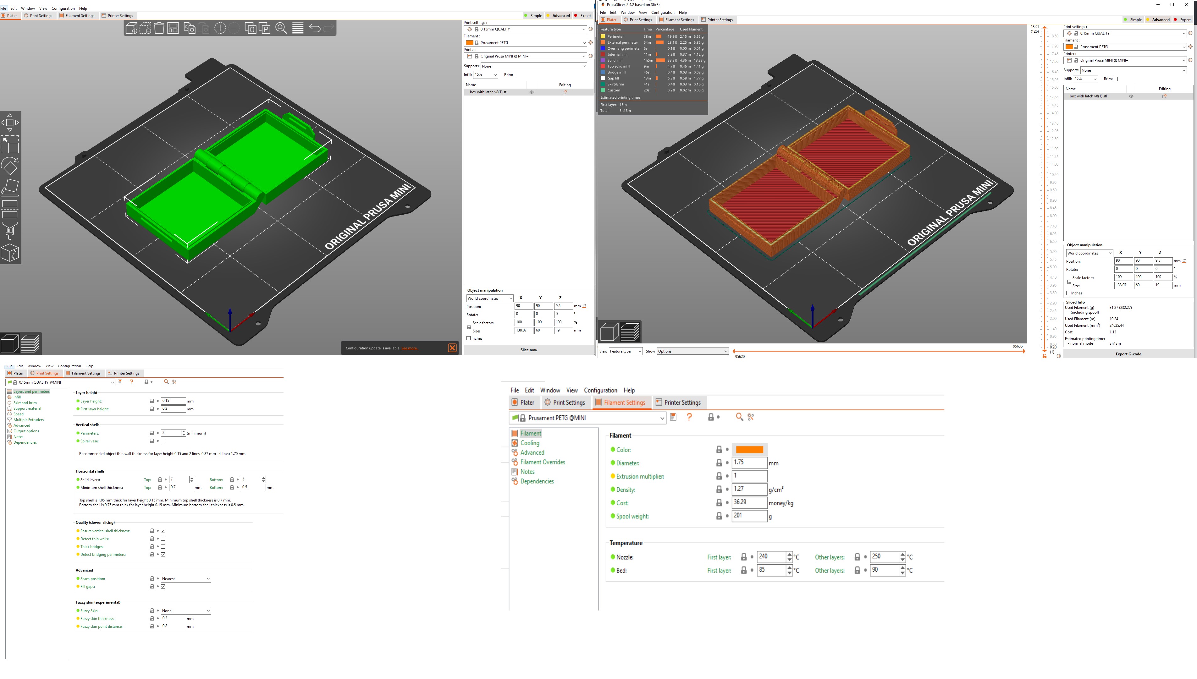
The most basic setting is setting the position of the object to fit the print area or printer bed.
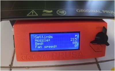
The goal is that the object is firmly attached to the base so that the object does not shift or deform while being printed.
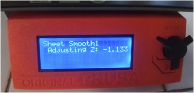
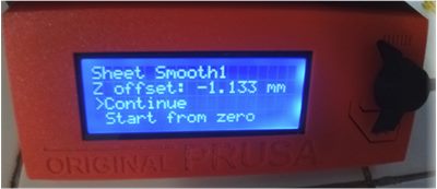
I used nine-point calibration – commonly known as software-assisted manual calibration (manual calibration on PrusaSlicer 2.4.2 based on Slic3r– to assist in calibrating the printer for optimal performance through software adjustments to the carried out to produce the best possible print quality and allow easy removal of supports and raft structures.
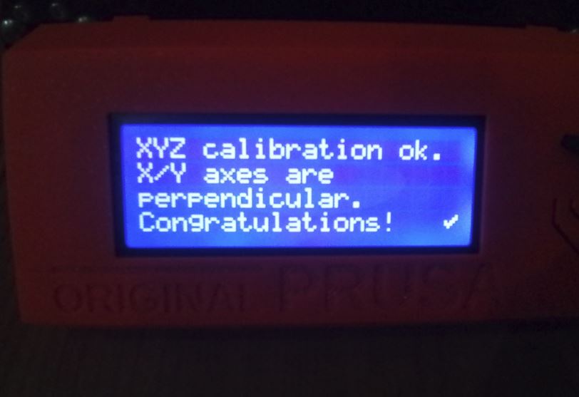
From the three possible calibration methods, manual calibration provides the most effective results. Since its nine points cover the entire build plate area, this model these tend to print perfectly.
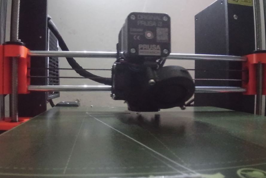
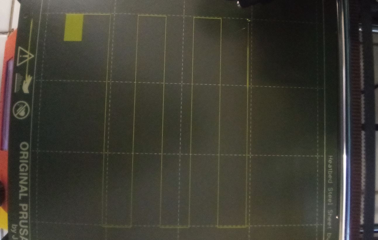
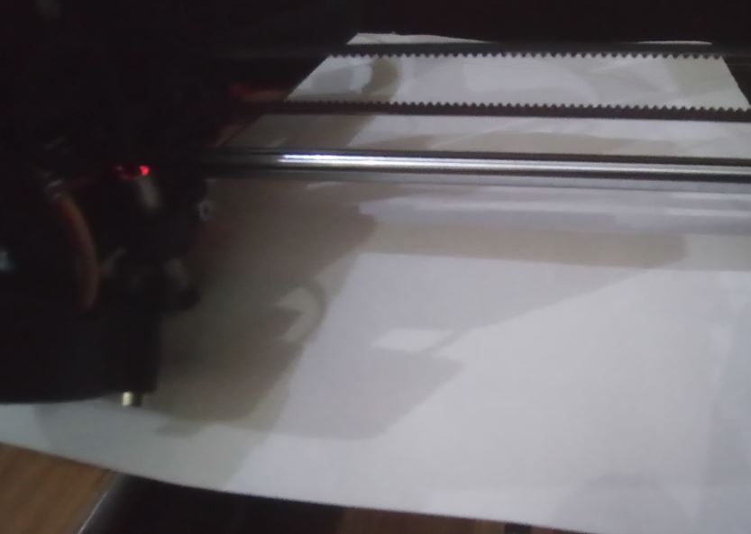
I perform routine calibrations at nine points before the printer’s first print job and each time the printer is moved to a new location. I also use a standard sheet of paper, which is approximately the same thickness to judge whether the nozzle is too close or too far from the build surface. During this operation, the printer is located near the computer for easy observation of what is happening at the printer nozzle.
Results
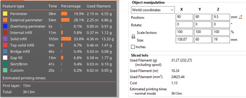
In printing process, I assumed there were no errors in my STL file, after uploaded my design to the 3D printer. The 3D printer used the instructions in the respective file to dictate where and how the material was deposited.
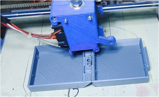
The 3D printer built the bottom layer first, after which it built the next-highest layer.
PLA filament which I used is thermoplastic material for this process. Thermoplastic pellets or beads are extruded out of the printer head, at which point they fall onto the bed where they form the printed object.
What to improve for next projects using 3D scanning and printing?
Here are some points toenhance and capture quality scans from the start:
- Controlled Environment.
- Use Proper Fixture.
- Scanning Challenging Surfaces.
- Calibrating your 3D Scanner for Accuracy.
- Spinning the Object for Scanning.
- Scan with a Dark Background.
- Use the Correct Scanner Settings for the Part.
- Training.