7. COMPUTER-CONTROLLED MACHINING
# 7. COMPUTER-CONTROLLED MACHINING
When I created my assignment (Fab-MDF table) using Fusion360, I worked within coordinate systems. Fusion360 will then output a G-code program and continue with Cut2D software which tells the CNC machine what to do and where to move. In this mechanism, CNC machines read 3D information from the G-code program using coordinate systems, so it’s critical to specify the origin point (0,0,0) precisely and ensure it matches my Fuion360 (3D computer-aided design (CAD) software).
When the machine finishes an operation and resets, it needs to know that “home” position so the next operation is dimensioned and positioned correctly. Most geometries intended for CNC machines are modeled as “parts” and the CAD software will typically have a single coordinate system.
However, newer CNC software is more sophisticated and allows the user to work with assemblies that have multiple parts and prepare each one separately for machining. In that case, you must select the correct coordinate system for computer-aided manufacturing (CAM), which can be different for parts and assemblies.
ASSIGNMENT
For this week’s task, we will use Fusion 360 for 2D design, as well as for preparing a CNC file - creating, setting up toolpaths. We used Cut2D Pro 11 software for CNC production, which is compatible with the equipment in the laboratory Zhongke ZK-1325 CNC machine.
Group Assignment
For group massignment, you can find in HERE.
Safety Induction Working with Computer Controlled Machine (CNC milling)
The machine has its own characteristics and configuration which you should take into account when identifying the hazards and assessing the risks. You will need to consider the following hazards:
-
ejection of the workpiece or cutter – make sure that they are secure before starting;
-
contact with rotating cutters and automatic tool changers (where fitted);
-
trapping and crushing caused by moving tables or machining heads;
-
unexpected movement or start-up caused by faults in the control system;
-
excessive noise emission;
-
the production of dust and chippings
-
automatic handling and loading devices (where fitted);
-
pneumatic and vacuum clamping devices (where fitted);
-
safe programming of cutting tool rotation and approach speeds compatible with the material being processed;
-
any new programmes should have a ‘dry run’ at slow speed in case of any mistakes, to avoid collisions etc.
One of the highest rates of accidents caused by contact with moving machinery. The majority of these are because of operator’s hands or fingers making contact with the rotating cutters. Analysis of accidents investigated by HSE has found that the most common causes were:
-
inadequate or missing guards;
-
inadequate or lack of operator training.
-
Test runout, alignment, speeds, feeds, materials, and toolpaths for your machine
Individual Assignment
Make (design+mill+assemble) something big –> Fab Table
LEARNING PROCESS
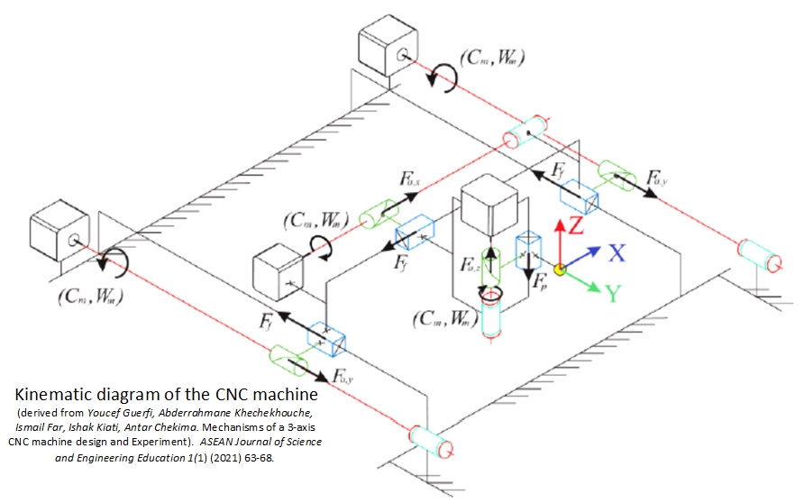
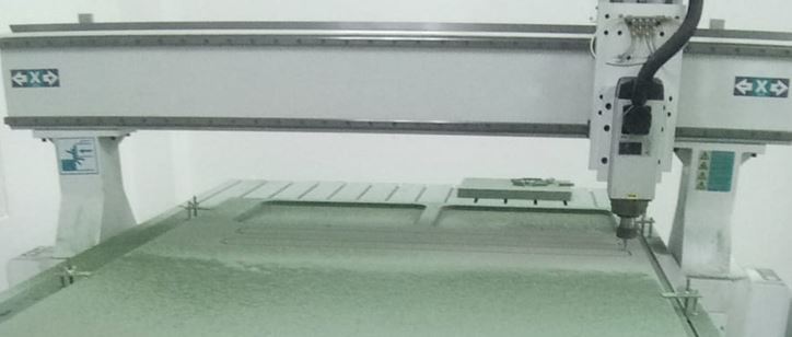
We used Zhongke ZK-1325 CNC machine with X,Y,Z axis working area 1300x2500x200mm; Spindle speed: 18000rpm, Spindle power: 6kW; tool diameter: 3.175-12.7mm; packing size: 3300mm2100mm2300mm; required placement: shop floor; Working voltage: 220V/ 1 phase 50-60HZ.
CNC router is an automated machine with a program control system. The control system can logically process and decode the program with control code or other symbolic instructions to cause the machine to operate and machine the part.
This machine has a constant linear speed cutting function. The same line speed can be used for the end face and the outer diameter of different diameters.
It can ensure that the surface roughness value is small and consistent, which is very suitable for many varieties of small and medium batch parts.
Linked to the group assignment page
For the Group Asssignment you can find in THIS_SITE.
Documentation of our Design Project for This Week
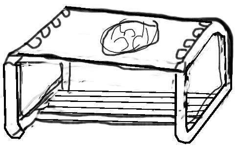
Manual Design Sketch Fablab Carved Logo Table
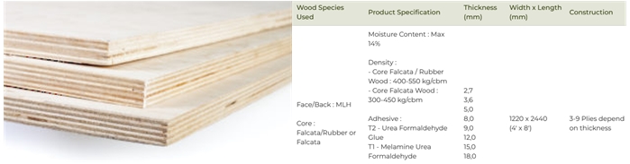
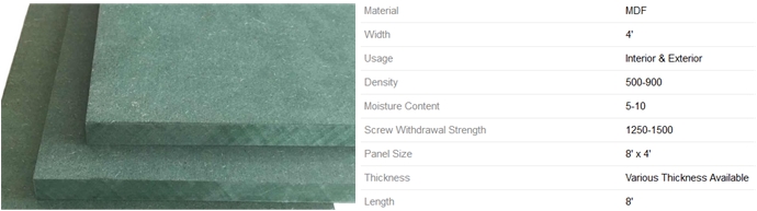
We used multi-layer plywood 15 mm thickness and medium density fiberboard (MDF) 15 mm thickness.
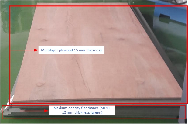
For individual assignment, we used material density fiberboard which composed primarily of softwood, although some individual brands may contain a higher percentage of temperate hardwood.
Standard MDF is used to manufacture table tops, door panels and drawer fronts with moulded edges or profiled surfaces.
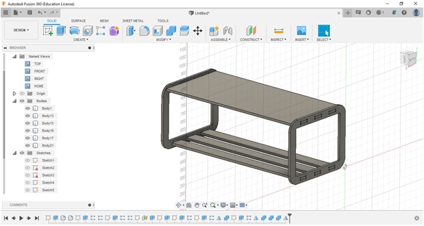
Our Fab-Table Design
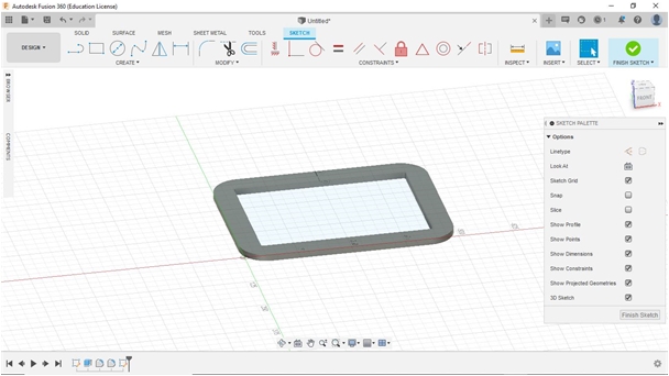
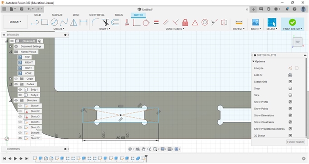
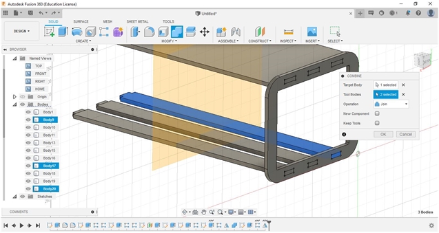
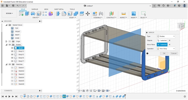
To design the Fab_Table, we used Autodesk Fusion360 for 3D sesign. We drew each and developed from our sketched (2D/handled/manual). After finished using Fuusion360 we continued to export into a dxf.extension file to be processed in CAM software (Cut 2D Pro) then transfer into milling process.
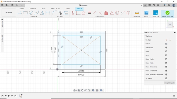
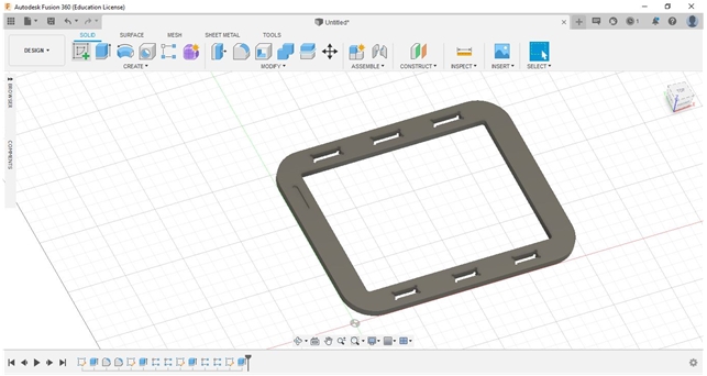
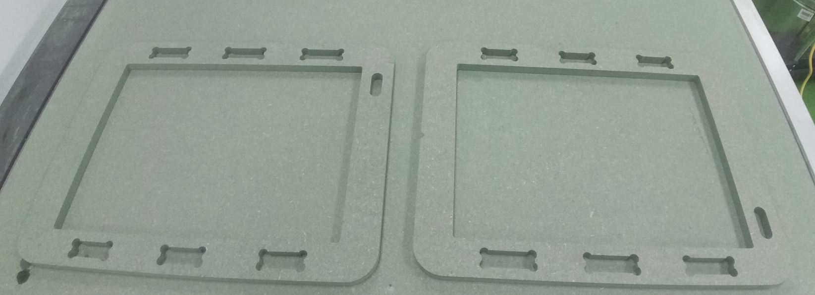
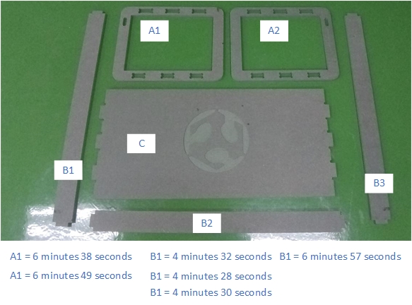
From the manual sketch, I continued to design a rounded-rectangle table leg (rear) which will later be used as a support for the surface and horizontal reinforcement at the bottom. I made two pieces for the left and right side.
The dimensions of each support leg are 50 cm x 40 cm x 1.8 cm (without changing the thickness of the material; green medium density fiberboard). with the open part as the inside size is 39 cm x 29 cm (with a distance between the inside and outside about 5 cm).
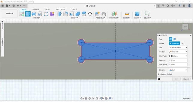
For this assignment, FabLab table, I did not use nails or pegs to unite and assembly the parts to one another. I used the press-fit assembly concept which we have learned previously.
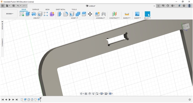
The effect of cutting (Kerf factor) needs to be considered, in this design the slots that we made we add each about 0.4 mm (0.2 - 0.6 mm) so that when paired them, I wanted to make sure they can be installed correctly.
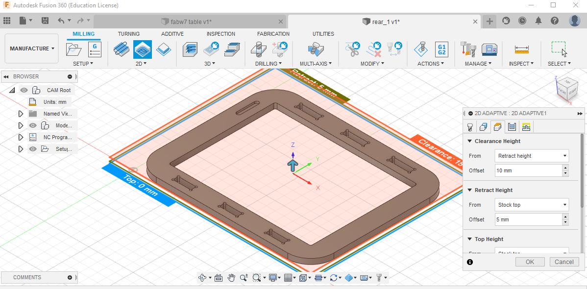
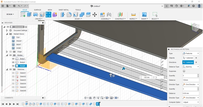
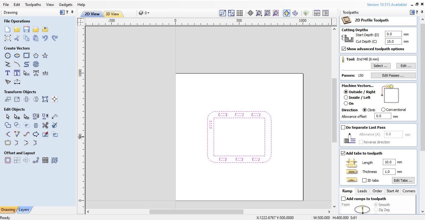
For 2D Adaptive, on clearance height I used a retract height with an offset of 10 mm and a stock height of 5 mm.
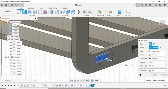
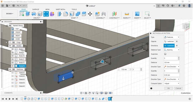
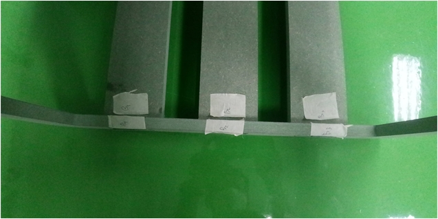
The assembly process and the connection between components through a press-fit form that has been designed requires precision, accuracy, and size accuracy with the appropriate allowance so that it is connected without gaps and tight (does not change position).
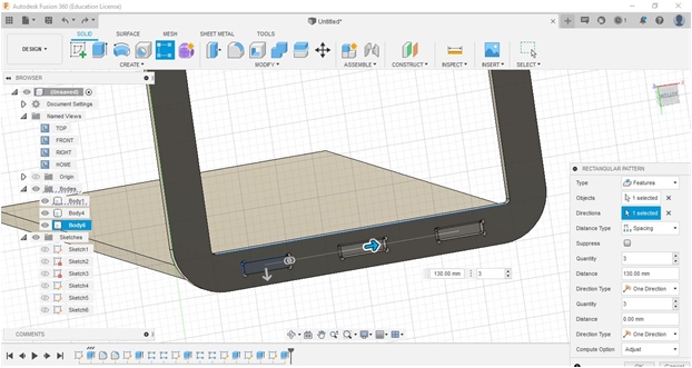
At the connection-points of the corners or diagonals, I gave allowances in the shape of a circle to anticipate if there is incorrect in precision or size, whether it is larger or smaller, so that if there is a discrepancy it is easier to handle it.
The position and precision of the placement of the bottom end of the support with the rear hole is largely determined by the accuracy of measuring the connection area.
I really hope there will be a perfect fit for this material with this mill.
In addition to the aspect of strength, the design that I made also tried to save on the use of materials and reduce waste.
For assembly process, in a group assignment, I found just the right fit for a 15 mm lumber-core, and since I wanted a tight fit, I set the joint clearance to 0.25 mm.
To anticipate incorrect joint area, I added 5 mm diameter circle whole parts of corner inside.
Finally, I finish the design data and learn about joint-fit and kerf.
Documentation Our CAM-toolpath
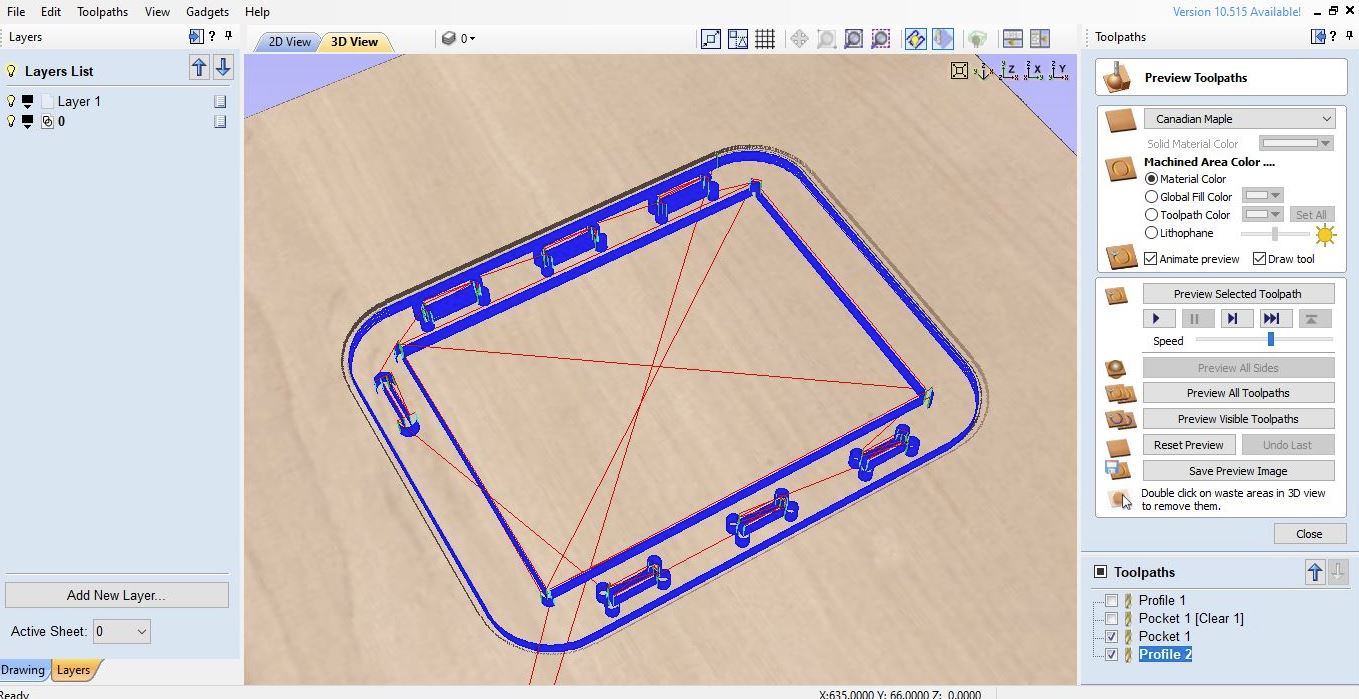
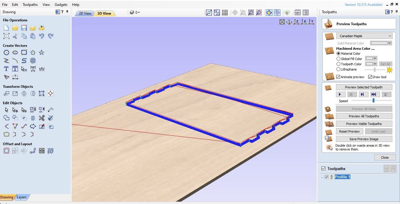
Many experiences and knowledge related with how to simulate CNC milling to optimize a wealth of machining process parameters including geometry pecision, material characterization, tool wear, machining time, material waste, and, at a more advanced level, heat effects, and more. I learnt how the trajectories that tools follow and they should be carefully considered and validated in toolpath. By verifying these paths, I could optimize the machining process and prevent the tool holder from clashing with the stock material.
After all the sketches have been created, we can export the sketch to a DXF file to be processed in CAM software (Cut2D Pro), by “right clicking” on the sketch and save as DXF, save the file.
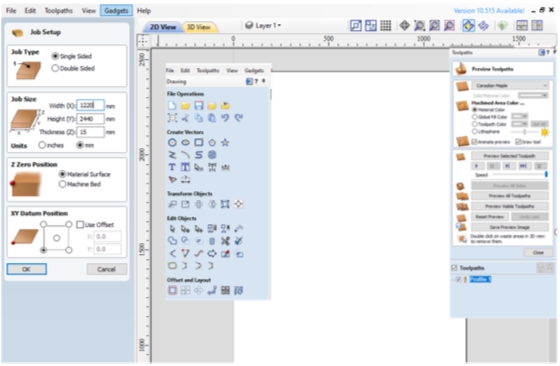
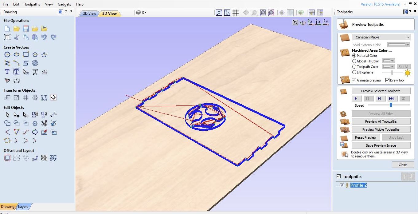
I used Cut2D Pro to produce complex 2D patterns with profile, pocket, drill and inlay toolpaths.
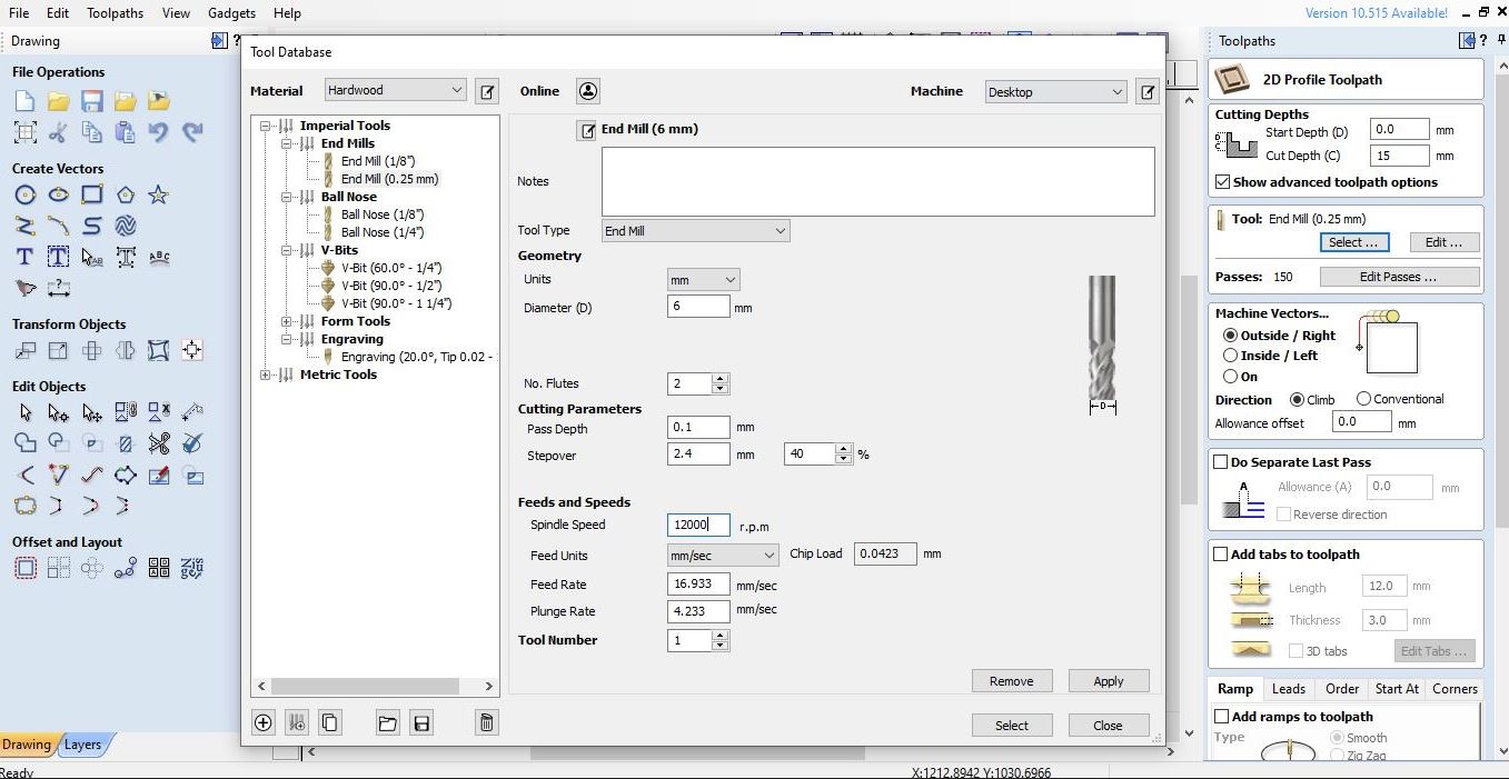
I had to set the unlimited job and toolpath size, true shape nesting & job set-up sheets. Cut2D Pro provides the tools to use vector drawing and editing tools for 2D machine routing, milling or engraving and cutting parts on a CNC Router.
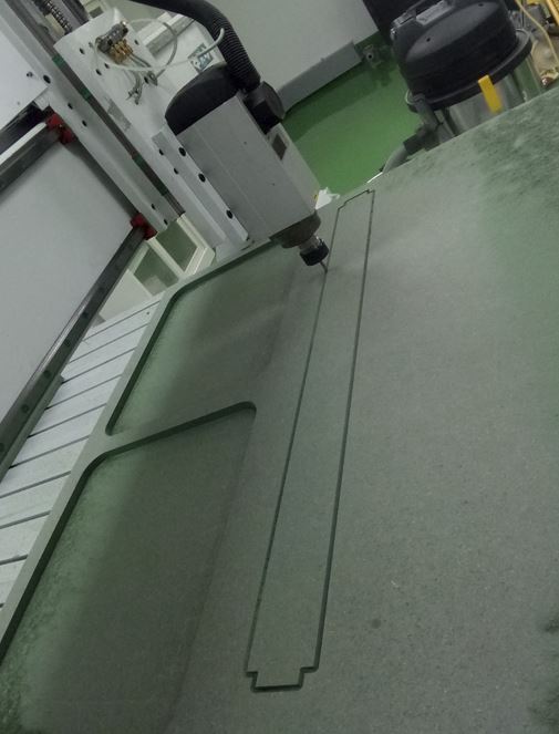
I started working on the rear or left and right side supports that function as body supports and lower reinforcements.
I used the toolpath and had to make sure that the imported curves are a single curve (not overlapping each other), inter-curves are interconnected (unbroken/no gaps), and all curves joint-fit in assembly process.
Almost the same process steps are also carried out on the upper body and lower support for reinforcement.
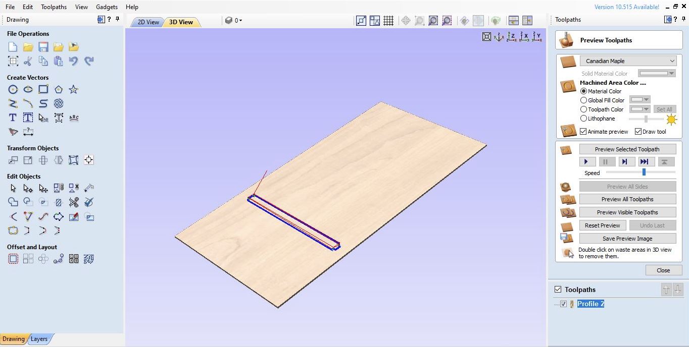
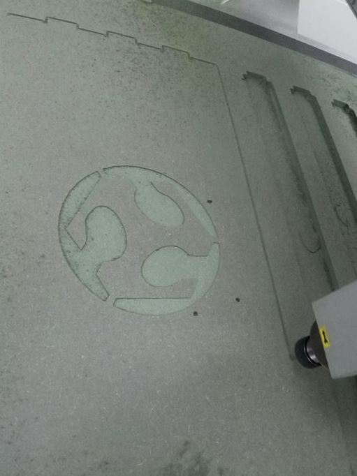
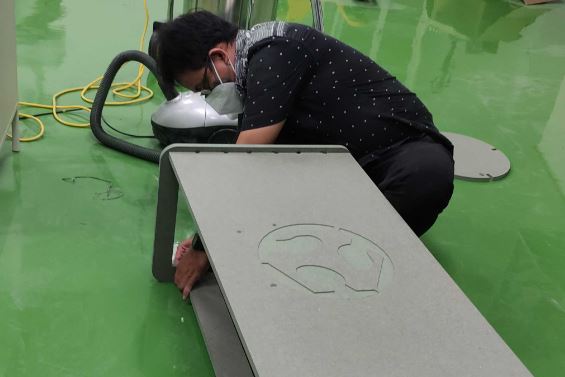
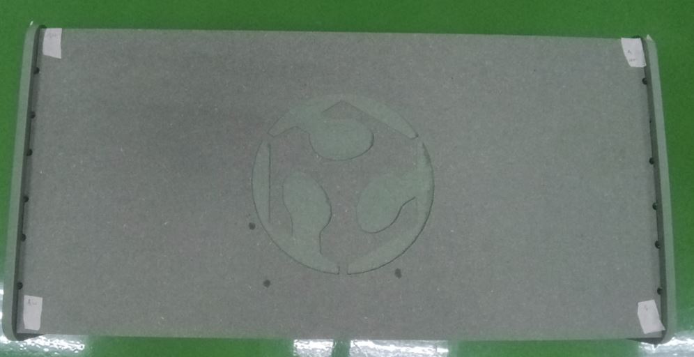
In this section, the engraving process is used to get the FabLab logo on the table surface with a depth of about 5 mm.
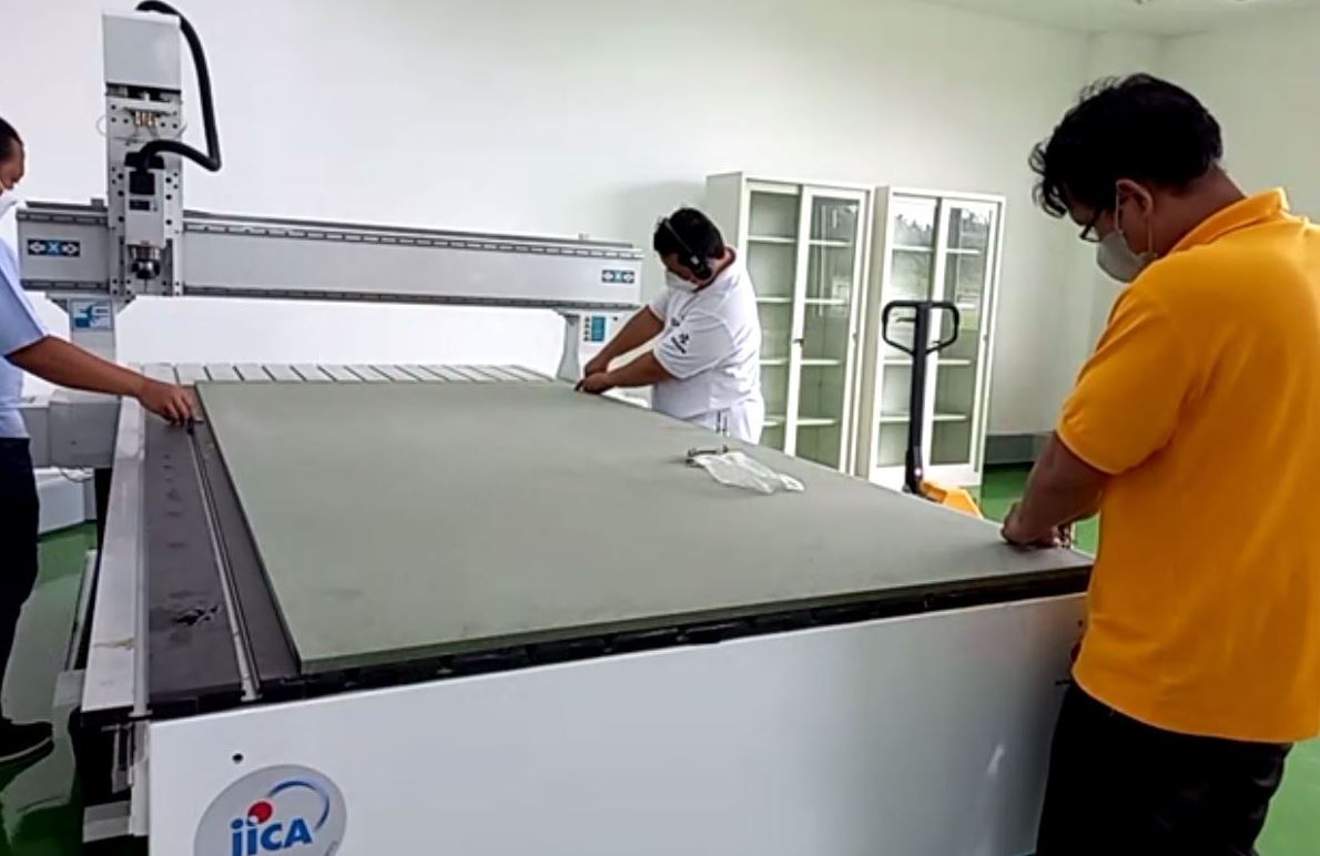
Milling Process
Before we start, for safety inductiona and avoid the problems in milling process, we have to prepare the machine bed by conducting these activities:
 .
.
- Choose a piece of green MDF and note down its dimensions, e.g. 16 mm thickness.
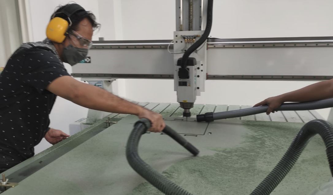
- Clean the bed from MDF dust and plywood chips and other stuff. Also clean the area around the machine. Make sure we can’t tip over chairs and other stuff.
- Check how flat the sacrificial layer is.
- Vacuum clean the bed and the board.
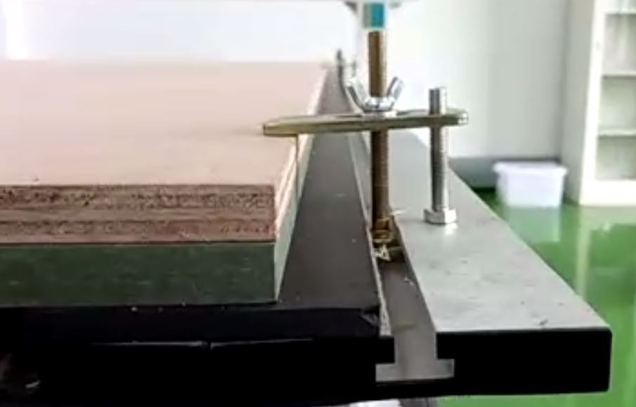
- Place the board on the bed, make sure all surfaces are touch the xy corner.
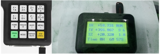
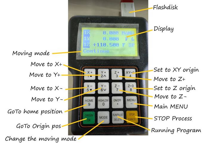
Tool settings related to the location and name of the design file, home and working area position (XYZ), milling speed, the home position and estimated time. I can work after restart operations are defined, the table is ready with the stock material, tools are installed.
we must always supervise the machine while it is working to ensure the suitability of the process and the character of the material that can break if it is unable to withstand the load or mechanical rotation of the machine.
The green color is a marker for identification purposes. The moisture resistance of this product does not come from the green coloring matter. Rather, from a special resin material used.
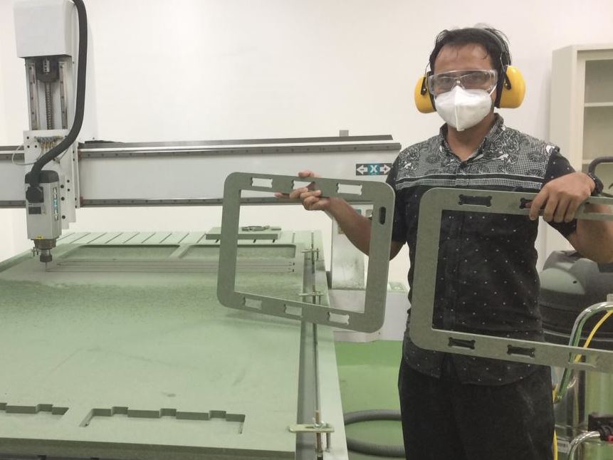
Documentation of our “something BIG”
I had to adjust/setting up the machine, using fixings, testing joints, adjusting feeds and speeds, depth of cut etc.)
Attach material (green MDF) to sacrificial layer with screws, make sure not to touch the screws with the spindle.
Make sure the emergency exits are freely accessible for operators and allowance for material handling.
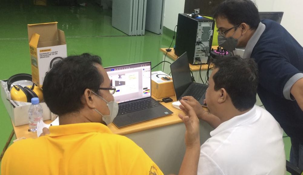
Discussing for design, flow, software (Cut2D Pro) setting, and simulation project of our projects.
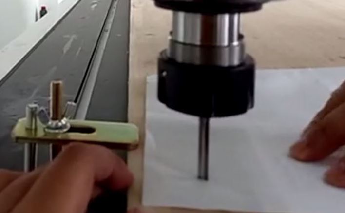
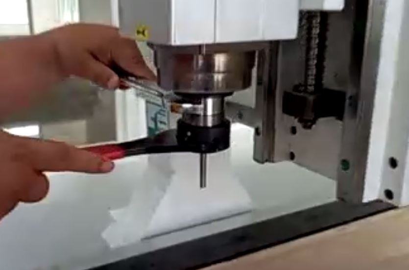
Determine an important parameter for our milling result is the milling bit.
2-flute (black one) - end-nose
1-flute (silver one, larger)
4-flute (shiny) - ball-nose
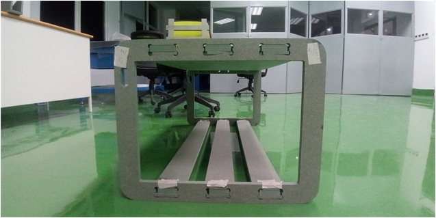
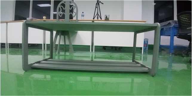
Assembly our components into final Fab-Table as one of our final projects.
Remove drill bit carefully, clean and store according to handling instructions
Described problems and how you fixed them
My mistake was not choosing the right machine vectors work in the 2D profile toolpath stage. I use “inside/left” with “clim” direction so that the size of the “base” is bigger than the column, so the joint process can’t fit together tightly (I had to add a wedge so that the components can be attached tightly and stably)
Included your design files and ‘hero shot’ photos of final object
These are our results “Fab_table”
LEARNING OUTCOMES
After conducted these assignment, I got more experience and knowledge about:
-
Big CNC milling work mechanism, characteristic and their parameter what being used
-
Safetyinduction wrking with the big CNC milling
-
Using 3D and 2D design for CNC milling
-
Controlling and evaluating CNC milling process