3. COMPUTER-CONTROLLED CUTTING
# 3. COMPUTER-CONTROLLED CUTTING
1. Weekly Brief Summary
After joined Prof.Neil’s class on Wednesday 9th Februari,2022, I continued to set up the laser cutter and vynil cutter at field reserch center (FRC) of my campus. I created and designed simple assignment using InkScape and FreeCAD 0.19. I learned how to use those software from Youtube and some reference, then practiced to apply 2D and 3D data with parameters. Computer-controlled cutting is a subtractive manufacturing method in which computer-generated instructions tell a machine how to cut a material. I used a laser cutter and a vinyl cutter for this week assignment. For each, I prepared 2D and 3D CAD drawings, which I imported into JobControl 11.30 for Trotec laser cutting and Brother Canvas Workspace for vynil cutter that sent cutting instructions to a machine.
2. Weekly Assignment Requirement
I had two main assignment, group assignment and individual assignment :
3. Group Assignmemt
-
Characterize our laser cutter’s focus, power, speed, rate, kerf, and joint clearance
-
Document our work to the group work page and reflect on our individual page what we learned
-
Understand the capabilities, precision and limitations of our laser cutter
-
Focus on one or two materials,
-
Try making a number of short straight line cuts with the laser properly focused
-
Incrementally (a millimeter or 2 at a time) out-of focused
-
Observe the results
For Group Assignment, I pushed in HERE
Individual_assignment
-
Design, lasercut, and document a parametric press-fit construction kit, which can be assembled in multiple ways.
-
Account for the lasercutter kerf.
-
Cut something on the vinyl-cutter
Learning Process
1. Laser Cutter
In this assignment, parametric design involves using parameters, or rules that define certain aspects such as length and width. They can be used to edit the design easily by entering new parametric values, instead of redrawing a whole design.
I started out in Fusion 360, sketching a leaf shape. Notice how the outline changed from blue to black. In Fusion, this happens when a sketch is fully constrained. The constraints I mostly used were the equal, horizontal/vertical, perpendicular, and midpoint ones. After sketching the dimensions, I fully constrained the object, so it was locked in place. I could then use the ‘Change Parameters’ feature to label and change the distances.For this assignment, I used cardboard (2 mm) to create a parametric press-fit construction kit.
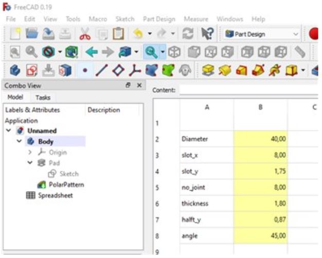
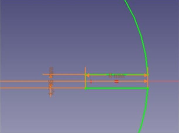
In creating parametric press-fit construction kit, I wanted to make a kind of helicopter model. I used FreeCad 0.19 to design them.By quantifying the elements of a design in parametric design, you can generate a number of different patterns and easily modify them later.
- Making Parametric Model by FreeCAD and Inkscape
I designed, made, and documented a parametric press-fit construction kit, accounting for the lasercutter kerf, which can be assembled in multiple ways.
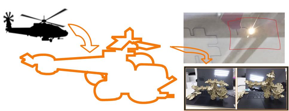
What I made: “Attack Helicopter”
Building the “attack helicopter” began with choosing an overall geometry and press-fit mechanism.
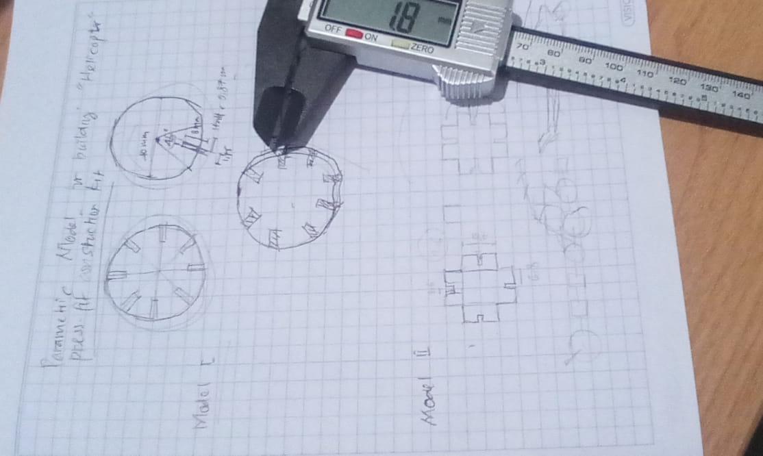
After finished for skecthing, we continued to design using FreeCad for constructing parametric press-fit model.
The images designed with FreeCAD are then exported to Inkscape for further copying and printing using a laser cutter.
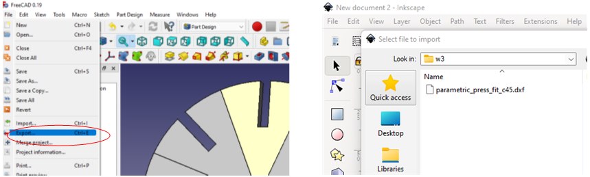
- Making SVG File from FreeCAD and Inkscape
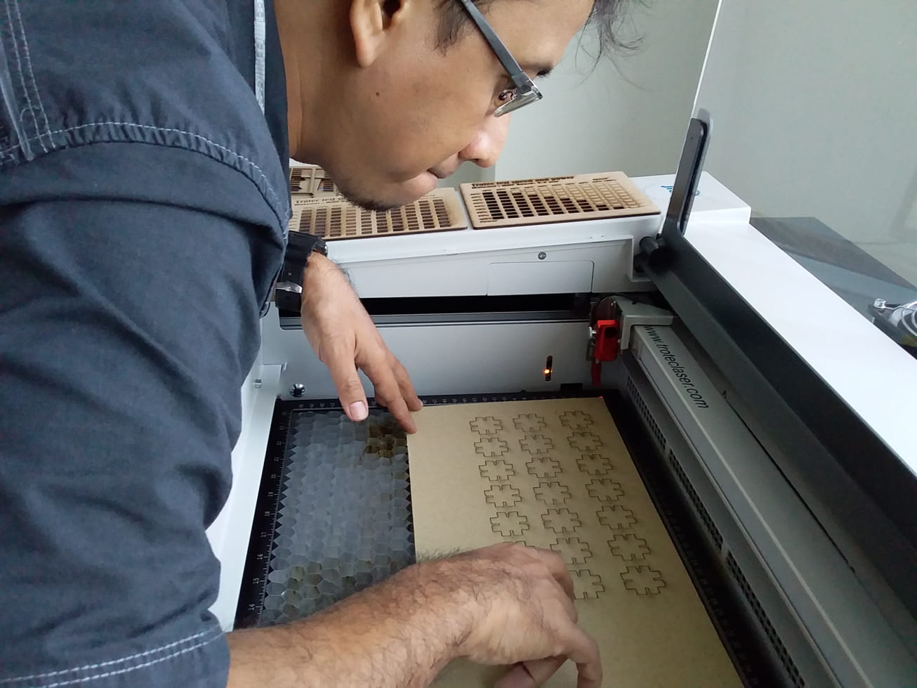
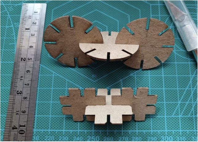
I switched to a tougher type of paper, notecards, and began cutting out the pieces to determine a basic geometry.
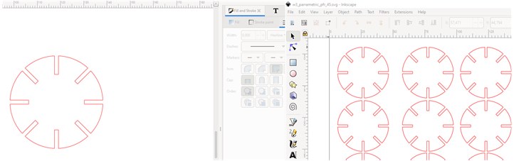
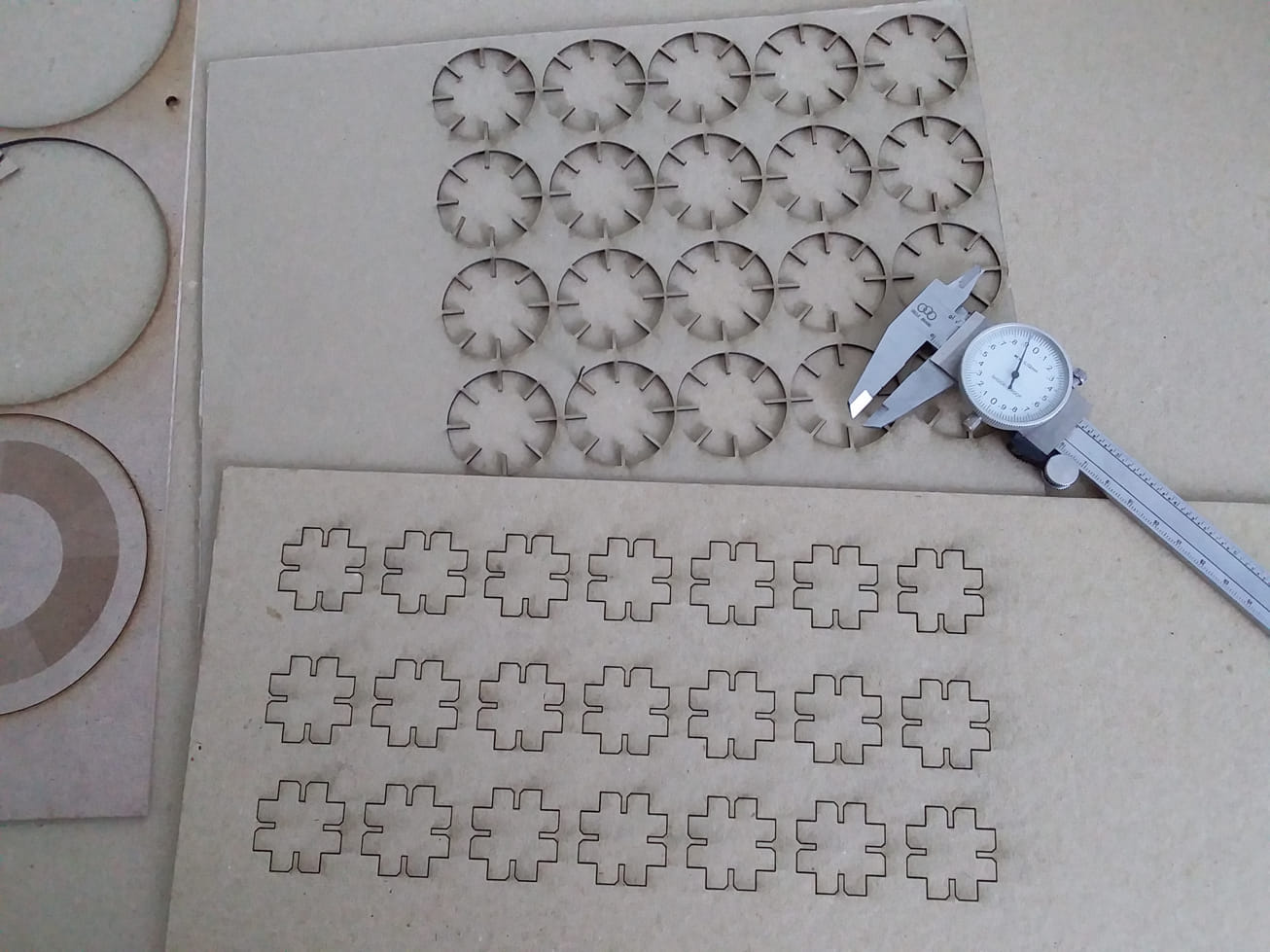
after I observe the circle shape with a diameter of 40 mm using cardboard paper with a thickness of 2 mm is still less attractive. then I continue to make a second model with a square shape for the same thickness of paper.
I tried manually via inkscape to create a second model to complement the first component. First I make one piece or one piece, then I duplicate according to the number I need to build an attack helicopter.
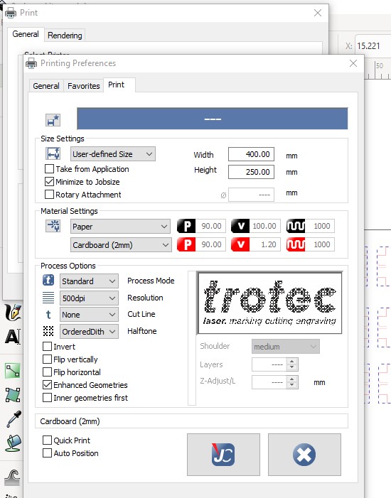
- For cutting and engraving on the file in inkscape, we need to make at two “objects”. One object will be the engraving and one will be the cut outline.
- fine (red) lines for cutting (if you need to cut)
- standard (black) lines and fills for engraving
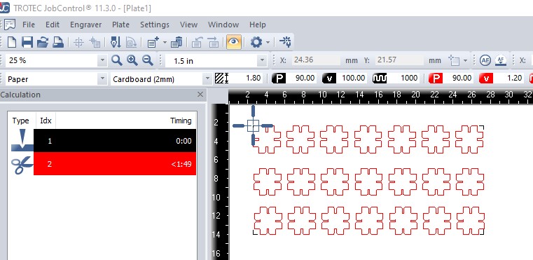
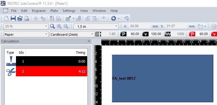
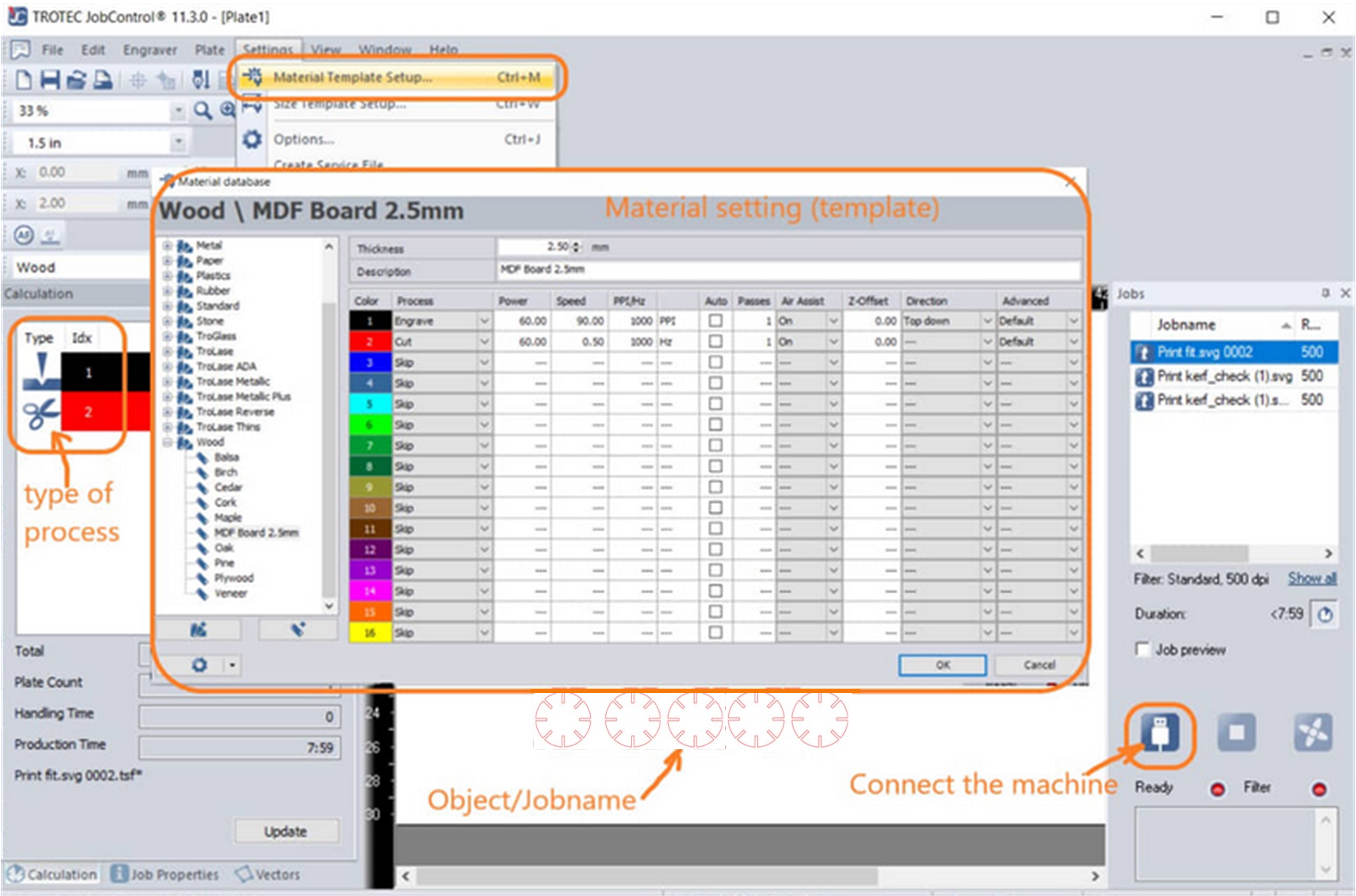
We used Trotec 100 CO2 laser cutter to work like most other laser cutting machines.
-
Very thin lines (<= 0.01mm or < 0.25pt) are coded with a color and then cut according to settings for each color.
-
Geometry for engraving is also encoded with a color and then engraved according to settings for each color.
-
Alternatively there is a “picture” mode that takes into account all objects for engraving, i.e. it will do grey-scale dithering.
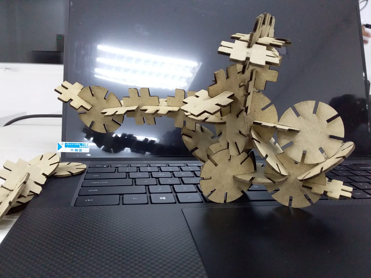
And finally I could made them…
Assembly
My
2. Construction Kit
The results of the study showed a clear process in each phase of the activity, and the explanation complemented by obstacles or problems encountered and problem-solving. Failures that occur in the creating parametric press fit kits for multiple assembly process provided learning that digital design and digital fabrication are a unified, interconnected process. The opportunities and challenges of digital fabrication applications in the architectural world are further interesting considerations to discuss.
3. Vynil Cutter
Speed, Power, Frequency Rate, Pass:
- On a few different materials (cardboard, wood, paper, leather, acrylic, fabric, etc)
- Try different combinations of these 4 parameters.
- Different materials and different thicknesses will require different settings.
- Try to discover what generates the best cutting result for each material (and systematically record these results for future lab reference)
-
Keep in mind that the general rule is that we shouldn’t have to use full power unless the material is thick or tough to cut.
--> in this case, 100% Power setting will reduce the longevity of our laser tube. -
A lower Power setting can be offset by…reduced Speed and increased number of Passes, for example
- An exercise to consider…what is the lowest cutting Power setting possible for a given material and thickness…cutting at reduced Speed (say 50%) and increasing number of passses (say 3)
- Also play with (Frequency) Rate (keeping other settings constant)…to see the difference between higher and lower percentages
- Kerf & Clearance: …will require us to measure the expected (modeled) dimension vs actual (cut) dimension…
- Make offset adjustments to our modeled dimension, to get desired real world dimensions
The ScanNCut is a digital cutting machine with a built in scanner - the only type of it’s kind out there! Other digital cutting machines can cut multiple fabrics and materials but to have the scan function really opens doors.
Machine_use_instruction
We use BROTHER SDX1200 we use scan and cut machine to create laptop sticker for example in this week assignment. We got more information the the manual operation which downloaded from this side.
Tutorial_video
This video explain about how to work with Brother ScanNCut to make simple 2D design.
Designing
-
2D vector software >> Inkscape
-
Create a design >> convert to path >> export as .SVG or .PDF
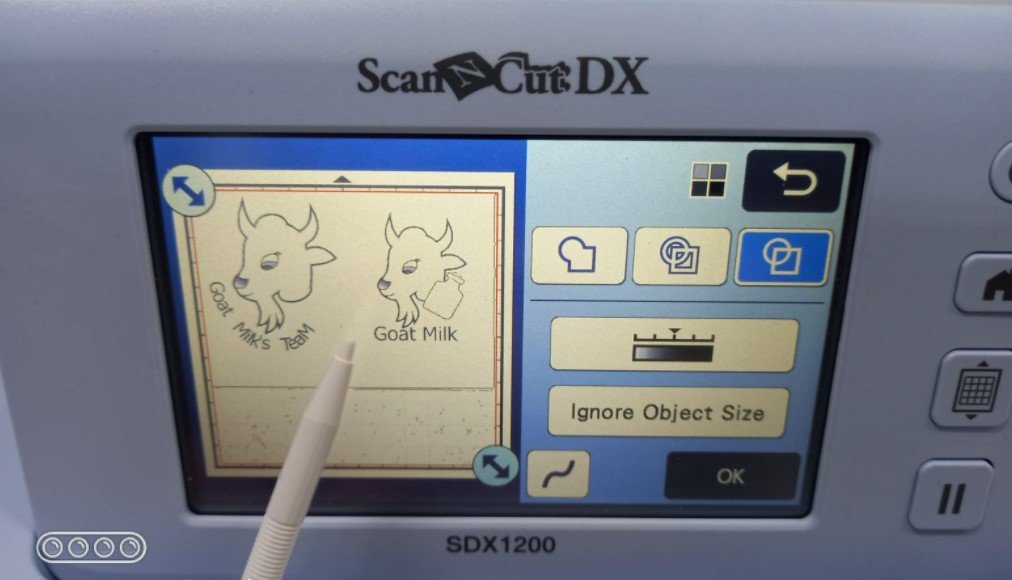
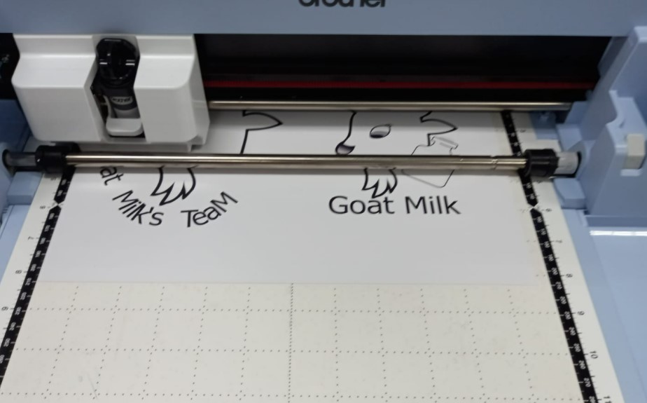
In this assignment, I designed a goat head with milk bottle which represented my project (quality test for goat milk).
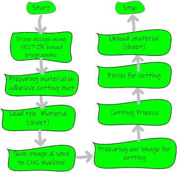
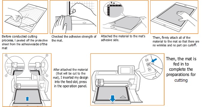
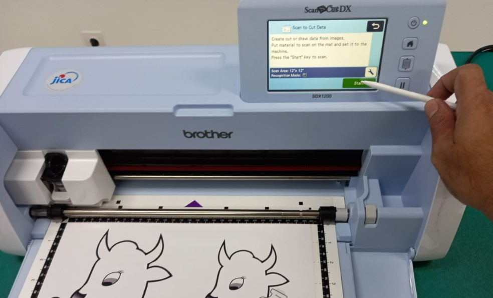
Before I worked with Brother SDX1200 (cutting machine), I had to prepared the material and design on the sticky mat.
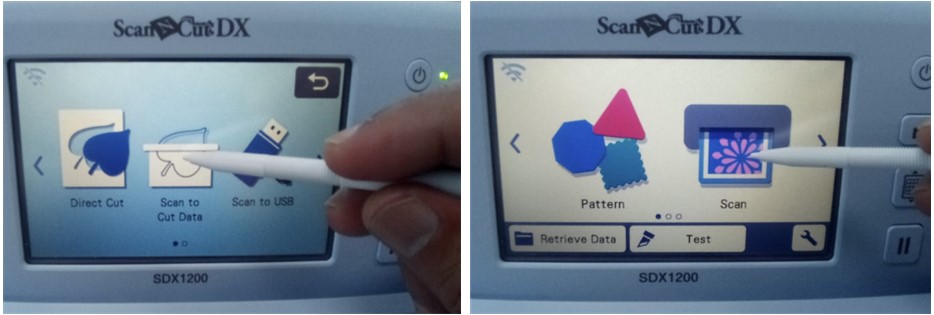
After load them (material and design), I started for cutting process.
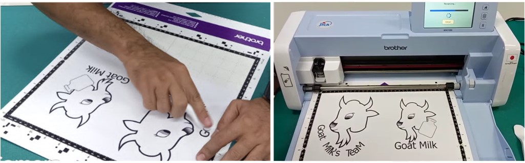
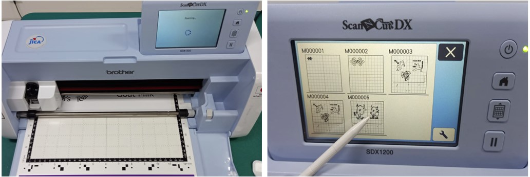
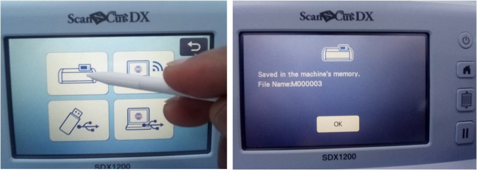
I saved my file/my design in vynil cutter storage.
 .
.
After scanning process, the result will be displayed on the screen.
 .
.
Beside scan and save them, this device also appropriates for USB and wife to transfer data.
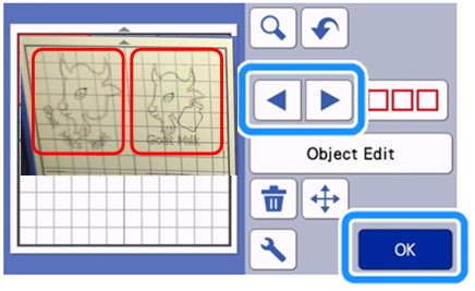
I started cutting process and used pattern selection.
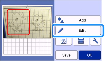
The following four pattern selection functions are available in the mat editing screen depending on my preference (a single pattern, desired patterns, all patterns, and specifying the selection area).
Test cut FORCE and DEPTH speed
Cut design
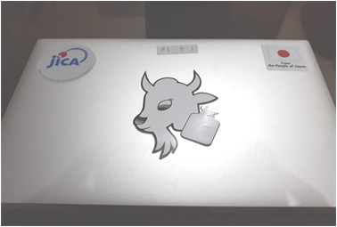
“Weeding” away unwanted “Negative” parts
Required Tool: xacto knife
Then we put them for our sticker laptop in image below.
Documentation Files
Learning Outcomes
After joined Prof.Neil Class and Conducted Our Assignment, we can be able to:
- Demonstrate and describe parametric 2D modelling processes
- Identify and explain processes involved in using the laser cutter.
- Develop, evaluate and construct the parametric construction kit
- Identify and explain processes involved in using the vinyl cutter.
Useful Link for References
-
https://support.brother.com/g/b/manualtop.aspx?branch=apweb&c=sg&lang=en&prod=hf_sdx1200eas
-
https://edutechwiki.unige.ch/en/Using_Inkscape_for_laser_cutting.