13. EMBEDDED NETWORKING AND COMMUNICATIONS
ASSIGNMENTS
Group assignment:
- Send a message between two projects.
The Group Assignment can be found in HERE.
Individual assignment:
- Design, build, and connect wired or wireless node(s) with network or bus addresses
Learning Process
-
Linked to the group assignment page and reflected what I learned individually of the group assignment.
-
Documented my project.
Communication Types
- SPI (Serial Peripheral Interface)
- I2C (Inter Integrated Circuit)
- UART (Universal Asynchronous Receiver/Transmitter)
I used them for networking communication, including between the microcontroller and I/O devices and for cable media (wire)
I2C
Is a serial communication protocol for two-wire (two-wire) which is used to connect two low-speed devices (low-speed) such as microcontrollers, ADC, DAC, EEPROM. Invented by semiconductor company Philips, widely used by most IC manufacturers Easy to use Can connect as many devices as possible Each I2C slave device requires an address obtained from NXP (the replacement company for Philips Semiconductors)
I2C COMMUNICATION CONFIGURATION
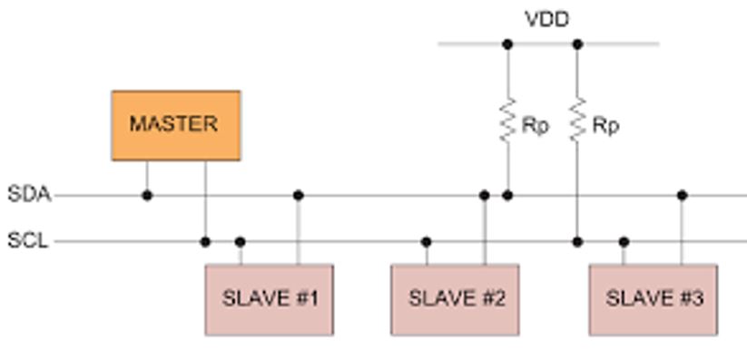
Uses only two cables/buses, SDA (serial data) and SCL (serial clock) Each wire is connected by a pull-up resistor to the voltage Vdd I2C shifter can also be installed which serves to connect two buses that have different voltages The communication network consists of at least one master and one or more slaves. The number of masters can be more than one
I2C Data Rate The I2C bus only operates at one speed, which is selected as the maximum speed In the specifications, the initial maximum data rate uses a clock frequency of 100 kHz. It can change to 400 KHz in fast mode There is also a high speed mode that can reach up to 3.5 MHz, and an ultra fast mode that uses a clock frequency of 5 MHz.
Addressing in I2C
Each slave in I2C has a unique address of 7 bits long Some I2C devices have a fixed address, some can change in the lower bit address portion A device can also have an address as long as 10 bits, as specified in the specification The 7 address bits are placed in bits 1 to 7, while bit 0 is used as a read or write signal for the device The master does not need an address because it generates the clock (via SCL) and selects the address of the slave device.
I2C Protocol
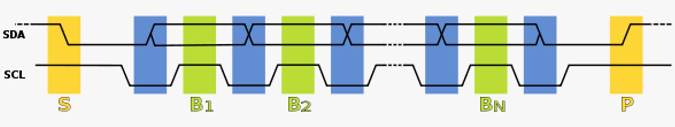
In normal status, SCL and SDA are logic High. Communication initiated by Master The master generates a Start (S) followed by 8 bits of slave device address and one or more data bytes. If the 0th bit of the slave address is set to Low, then data B2 to Bn will be written to the slave. Conversely, if the 0th bit is High, then the data is read from the slave. Either written or read, in the end it is the master who will generate the Stop. If this process is complete, then the path can be used by other devices.
SPI
A protocol that is widely used as an interface between microcontrollers and I/O devices such as sensors, ADC, DAC, SRAM, etc. SPI is a synchronous, full duplex master-slave protocol The data sent by the master or slave is synchronized by the clock generated by the master. SPI interface can use 3 or 4 wires
SPI configuration
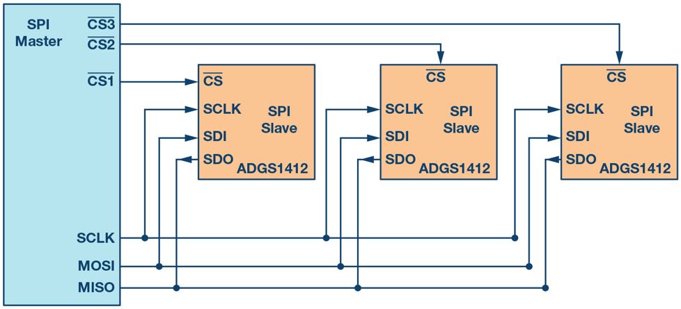
Signal types on 4-wire SPI are: Clock (SPI CLK, SCLK), Chip Select (CS, SS), Master out slave in (MOSI), and Master in slave out (MISO) The device that generates the clock is called the master SPI devices support much higher clock frequencies than I2C Chip select is used to select slaves. If the number of slaves is more than one, a different chip select signal is required for each slave MOSI and MISO are data paths, MOSI sends data from master to slave, and MISO is the other way around
SPI Data Transmission
To start communication, the master must send a clock signal and a chip select signal according to the target slave After that data communication between the two can be done simultaneously The sampling process and data shifting can be carried out on the Low to High clock transition or vice versa, according to the user selected Users can set CPOL and CPHA on the master to determine the polarity and phase to be used for sampling and shifting.
TABEL SETTING CPOL dan CPHA
| SPI MOde | CPOL | CPHA | Clock Polarity in Idle State | Clock Phase used to sample and/or shift the data |
|---|---|---|---|---|
| 0 | 0 | 0 | Logic LOW | Data sampled on rising edge and shifted out on the failing edge |
| 1 | 0 | 1 | Logic LOW | Data sampled on rising edge and shifted out on the failing edge |
| 2 | 1 | 0 | LOgic HIGH | Data sampled on rising edge and shifted out on the failing edge |
| 3 | 1 | 1 | Logic HIGH | Data sampled on rising edge and shifted out on the failing edge |
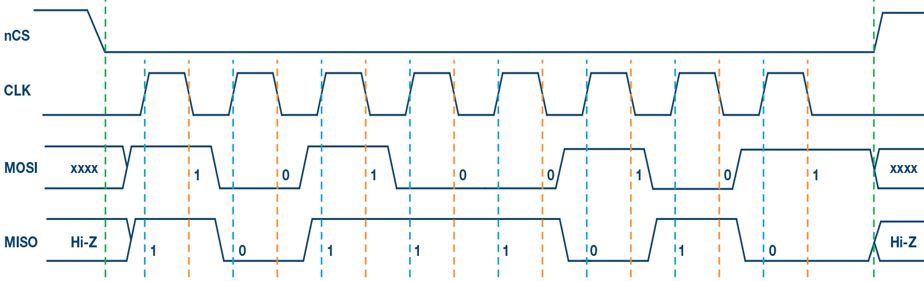
SPI Mode 0
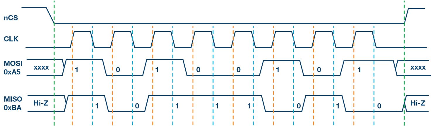
The start and end of data transmission are indicated by green dotted lines The sampling edge is indicated by the dotted orange line The shifting edge is indicated by the dotted blue line
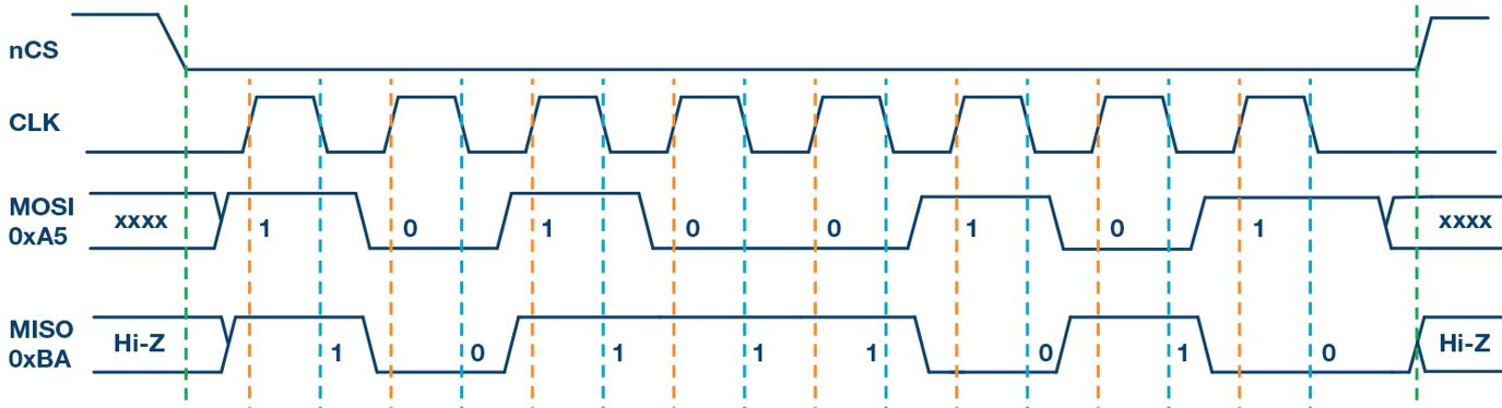
SPI MOde 1
The start and end of data transmission are indicated by green dotted lines The sampling edge is indicated by the dotted orange line The shifting edge is indicated by the dotted blue line
SPI Mode 2
The start and end of data transmission are indicated by green dotted lines The sampling edge is indicated by the dotted orange line The shifting edge is indicated by the dotted blue line
SPI Mode 3
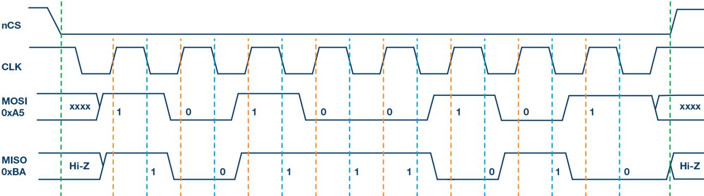
The start and end of data transmission are indicated by green dotted lines The sampling edge is indicated by the dotted orange line The shifting edge is indicated by the dotted blue line
UART
UART is widely used to connect GPS, Bluetooth, LoRA, RFID modules on Arduino, Raspberry Pi, or other microcontrollers. UART is not a communication protocol like I2C and SPI, but rather a physical circuit in a microcontroller, or a single IC chip. Its function is to send or receive serial data UART only uses two cables to connect one device to another. The third wire is ground.
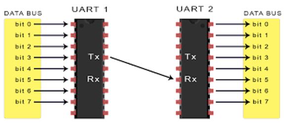
Communication with UART
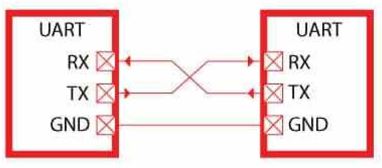
In UART communication, the sending device converts parallel data into serial data, while the receiving device converts serial data into parallel data again To connect two UART devices, the TX terminal of device 1 is connected to the Rx terminal of device two. While the TX terminal of device two is connected to the RX terminal of device 1. The GND terminal of the two devices is usually connected as a reference voltage value on TX and RX.
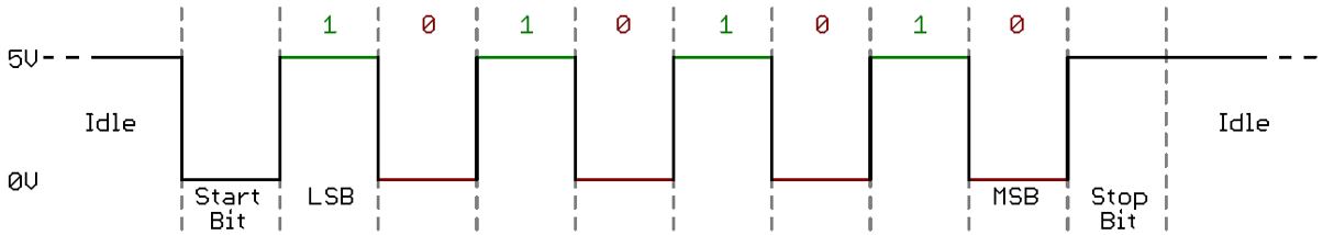
As the name implies, UART sends serial data asynchronously, where there is no clock that synchronizes the sender with the receiver. When the UART receiver detects the start bit, it starts reading the data at the same baud rate specified on the transmitter, until it detects the stop bit. In addition, the transmitter and receiver must also agree on a mutually defined data format.
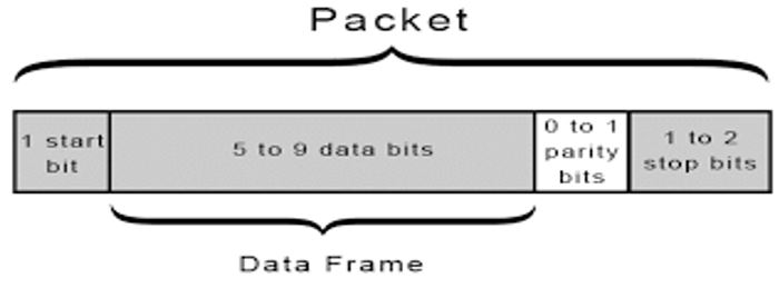
The format of the data sent in UART is called packet. It is this package that must be agreed upon by the sender and receiver. The data packet starts with 1 start bit, followed by 5 to 9 data bits. After that, 1 parity bit can also be added, and ends with 1 or 2 stop bits.
Learning Process
In this week assignment, I worked with I2C device to support communication in my final project.
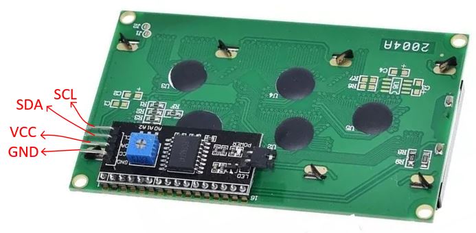
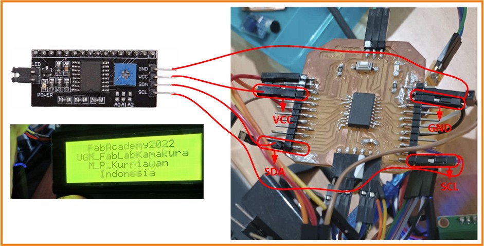
LCD 20 x 4
An electronic display is an electronic component that functions as a display of data, either characters, letters or graphics. LCD (Liquid Cristal Display) is one type of electronic display made with CMOS logic technology that works by not producing light but reflecting the light around it to the front-lit or transmitting light from the back-lit. The function of the LCD (Liquid Cristal Display) in this final project is to function as a data viewer in the form of characters, letters, numbers or graphics.
I used LCD I2C piggy back board
I used my ATtiny3216 board that I did in Week 10 assignment. I made 2 version with male and female connector.
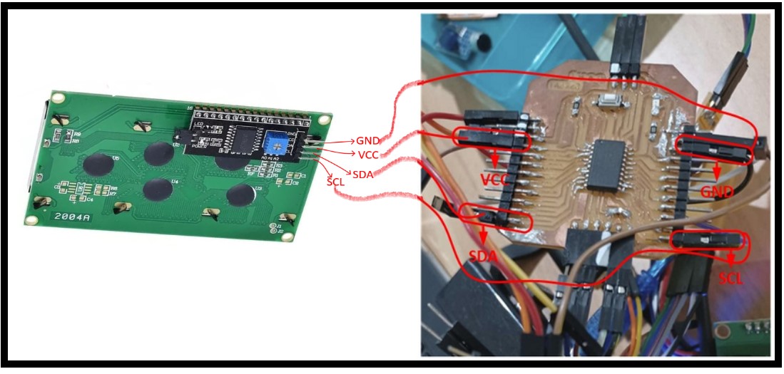
I continued to check the address for I2C communication.
// --------------------------------------
// i2c_scanner
//
// Modified from https://playground.arduino.cc/Main/I2cScanner/
// --------------------------------------

#include <Wire.h>

// Set I2C bus to use: Wire, Wire1, etc.
#define WIRE Wire

void setup() {
  WIRE.begin();

  Serial.begin(9600);
  while (!Serial)
     delay(10);
  Serial.println("\nI2C Scanner");
}


void loop() {
  byte error, address;
  int nDevices;

  Serial.println("Scanning...");

  nDevices = 0;
  for(address = 1; address < 127; address++ )
  {
    // The i2c_scanner uses the return value of
    // the Write.endTransmisstion to see if
    // a device did acknowledge to the address.
    WIRE.beginTransmission(address);
    error = WIRE.endTransmission();

    if (error == 0)
    {
      Serial.print("I2C device found at address 0x");
      if (address<16)
        Serial.print("0");
      Serial.print(address,HEX);
      Serial.println("  !");

      nDevices++;
    }
    else if (error==4)
    {
      Serial.print("Unknown error at address 0x");
      if (address<16)
        Serial.print("0");
      Serial.println(address,HEX);
    }
  }
  if (nDevices == 0)
    Serial.println("No I2C devices found\n");
  else
    Serial.println("done\n");

  delay(5000);           // wait 5 seconds for next scan
}
Scanning Result
 .
.
After that I programmed my LCD display based on the I2C address. Herewith the code to show the output:
//Fab_Academy Assignment
#include <Wire.h>
#include <LiquidCrystal_I2C.h>

LiquidCrystal_I2C lcd(0x27,20,4);  // set the LCD address to 0x27 for a 16 chars and 2 line display

void setup()
{
  lcd.init();                      // initialize the lcd
  lcd.init();
  // Print a message to the LCD.
  lcd.backlight();
  lcd.setCursor(3,0);
  lcd.print("FabAcademy2022");
  lcd.setCursor(1,1);
  lcd.print("UGM_FabLabKamakura");
   lcd.setCursor(3,2);
  lcd.print("M_P_Kurniawan");
   lcd.setCursor(5,3);
  lcd.print("Indonesia");
}


void loop()
{
}
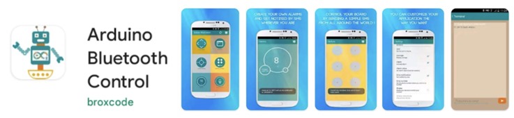
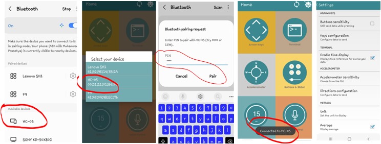
Bluetooth Connection
To run bluetooth for communication, I installed Arduino BlueControl (by broxcode from Playstore). It used to display bluetooth my work on projects which need bluetooth module and testing.
 .
.
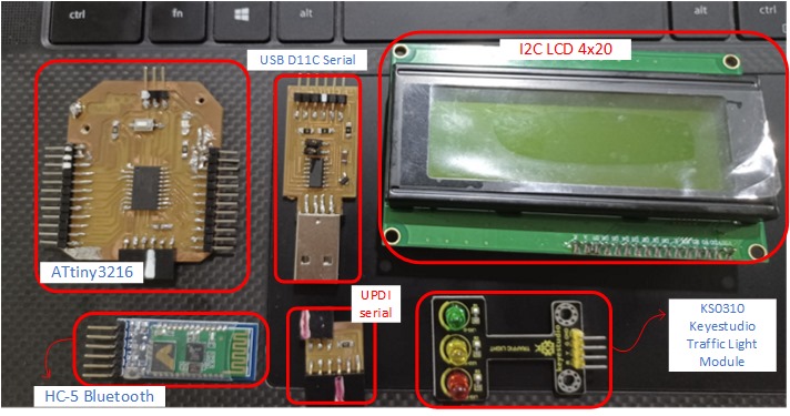
I also used KS0310 Keyestudio Traffic Light Module (Analog; working Voltage: 3.3-5v; Download_the_Code), as three separate LEDs, namely red, green and yellow light, to simulate the traffic light blinking via external connection. Convenient for wiring, on the module, it has integrated three LEDs, like LED-R, LED-Y, LED-G to able some light-interactive works, fully compatible with Attiny3216 my board system.
 .
.
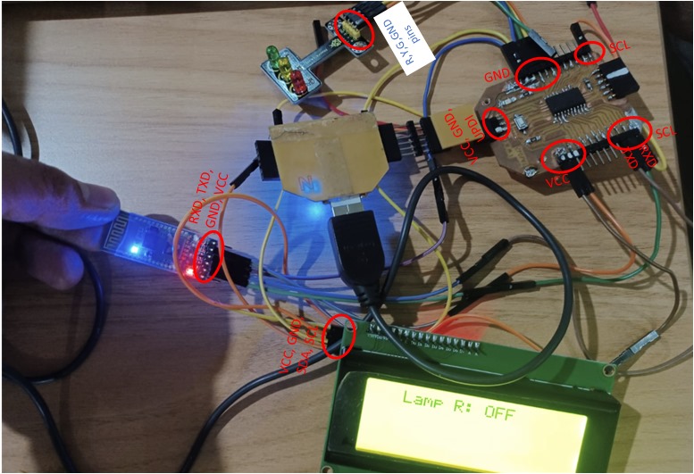
Here’s a wiring diagram combining the traffic light module, four jumper wires and my ATtiny3216board. I connected the traffic light module to my, R pin to Digital 14, Y pin to Digital 15, G pin to Digital 16, GND to GND.
 .
.
Then I connected them to set up configuration.
 .
.
Herewith my program using Arduino code and my port/board.
#include <LiquidCrystal_I2C.h>

LiquidCrystal_I2C lcd(0x27,20,4);

int PinR = 14;
int PinY = 15;
int PinG = 16;
String data;

void setup() {
  Serial.begin(9600);
  pinMode(PinR, OUTPUT);
  pinMode(PinY, OUTPUT);
  pinMode(PinG, OUTPUT);
  digitalWrite(PinR, LOW);
  digitalWrite(PinY, LOW);
  digitalWrite(PinG, LOW);

  lcd.init();                      // initialize the lcd
  lcd.backlight();

  delay(500);
}
void loop() {
  while (Serial.available() > 0) {
    delay(100);
    char data = Serial.read();
    //   data+=c;
    Serial.println(data);
    if (data == '1') {
      digitalWrite(PinR, HIGH);
      lcd.setCursor(3,0);
  lcd.print("Lamp R: ON ");
    }
    else if (data == '2') {
      digitalWrite(PinR, LOW);
          lcd.setCursor(3,0);
  lcd.print("Lamp R: OFF");
    }
    else if (data == '3') {
      digitalWrite(PinY, HIGH);
          lcd.setCursor(3,0);
  lcd.print("Lamp Y: ON ");
    }
    else if (data == '4') {
      digitalWrite(PinY, LOW);
          lcd.setCursor(3,0);
  lcd.print("Lamp Y: OFF");
    }
    else if (data == '5') {
      digitalWrite(PinG, HIGH);
          lcd.setCursor(3,0);
  lcd.print("Lamp G: ON ");
    }
    else if (data == '6') {
      digitalWrite(PinG, LOW);
          lcd.setCursor(3,0);
  lcd.print("Lamp G: OFF");

    }
  }
}
Results
After using my board with ATtiny3216, I used I2C 20 x4 LCD Display to communicate my board with the sensor and Bluetooth for program and data transfer. Interface 20x4 LCD display module consist with 4 line 20 character LCD module with on-board contrast control adjustment, backlight and I2C communication interface. I connected them to my ATtiny3216 board and LCD driver circuit connection module to simplify the circuit connection.
and this isthe result for bluetooth communication.
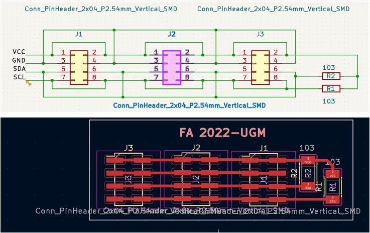
Working with Extended-Board
I also designed, built, and connected wired node(s) with network or bus addresses with extended board. I did this part to communicate between two boards with identifiable addresses wired (VCC, GND, SDA and SCL).
 .
.
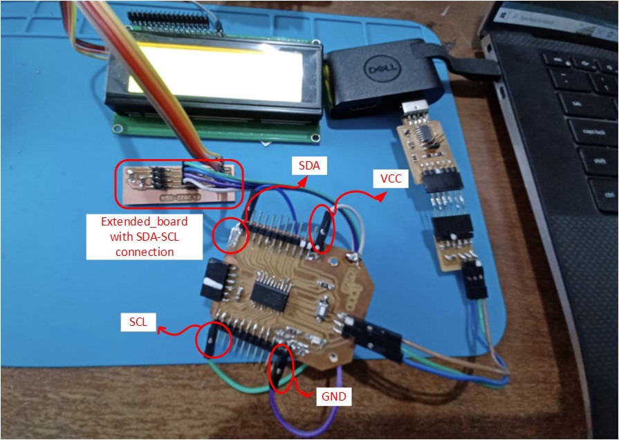
this picture below is the configuration.
 .
.
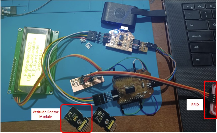
My Attiny3216 board is used the as master device, then communicating with an output or input that connects through i2c protocol for communication between slave devices.I connected 2 nodes with microcontroller that I have programmed (LiquidCrystal_I2C and I2C_Scanning). For next improvement, I will use Attitude Sensor Module and RFID (I will use VCC, GND, SDA, & SCL for both of them)
Learning outcomes
After conducted this week assignment, I got many experiences and knowledge about how to:
-
Demonstrate workflows used (I2C LCD display and bluetooth) in network design.
-
Implement and interpret networking protocols and/or communication protocols.