5. 3D Scanning and printing
At Fab Academy Dilijan we have a Makerbot Replicator 2.
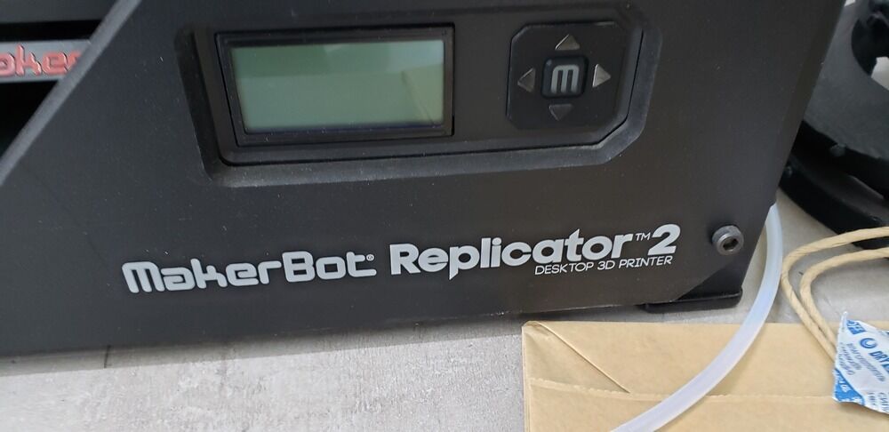
It’s a very interesting machine with lights that change the colour as the temperature of the nozzle also changes.
It starts from a blue colour that is when the machine is cold, to violet tones, that means that the machine is getting warm. And finally to a red colour that indicates that the machine is extremely hot (about 230°C).
First of all, as every new machine I read the manual.
1. Group assignment
If you have interest about our group assignment, you can click here.
There is a very interesting method about how we understand the precision of our machine. This means, how accurate and exact can be the machine that we use for the projects.
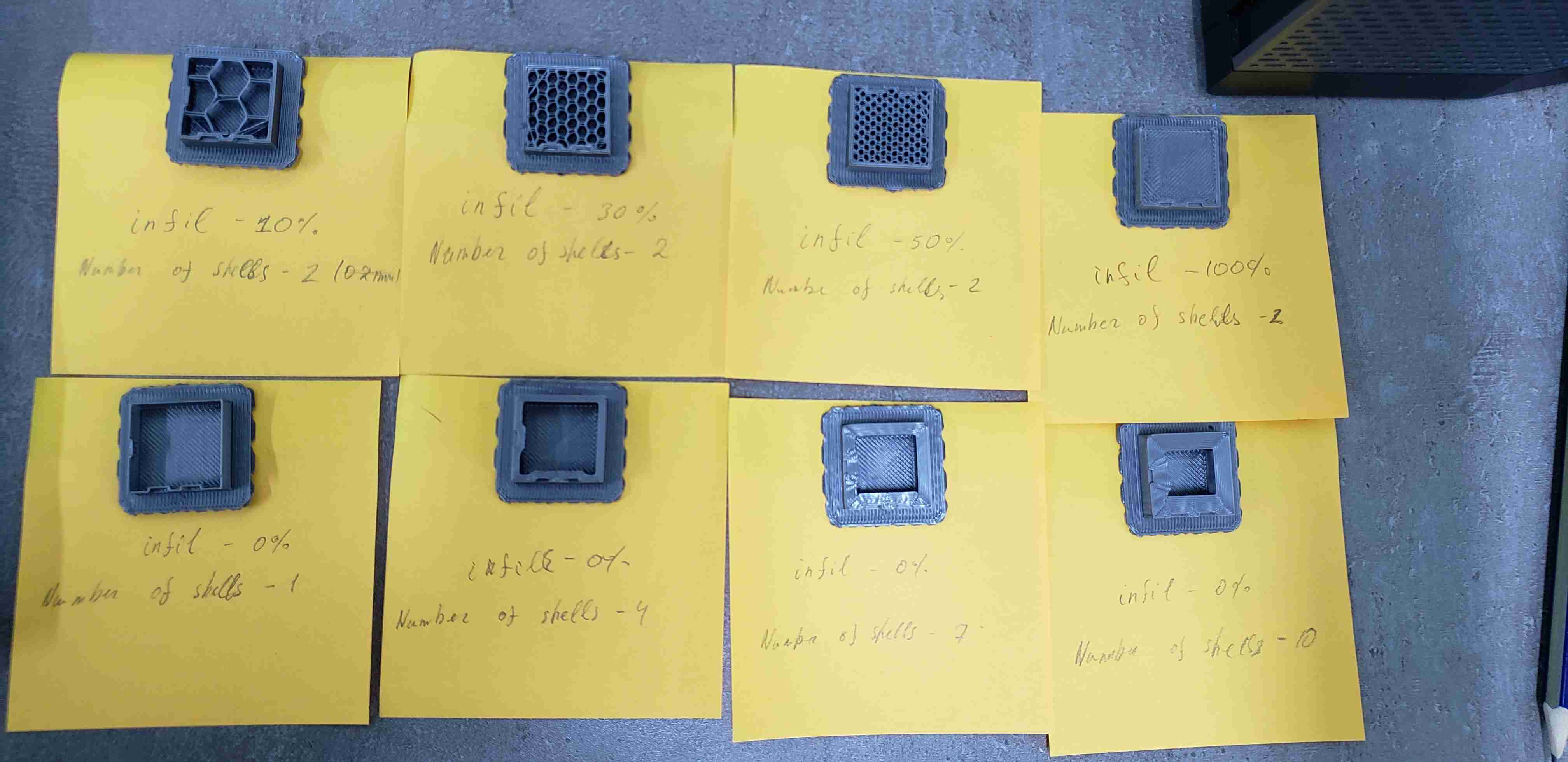
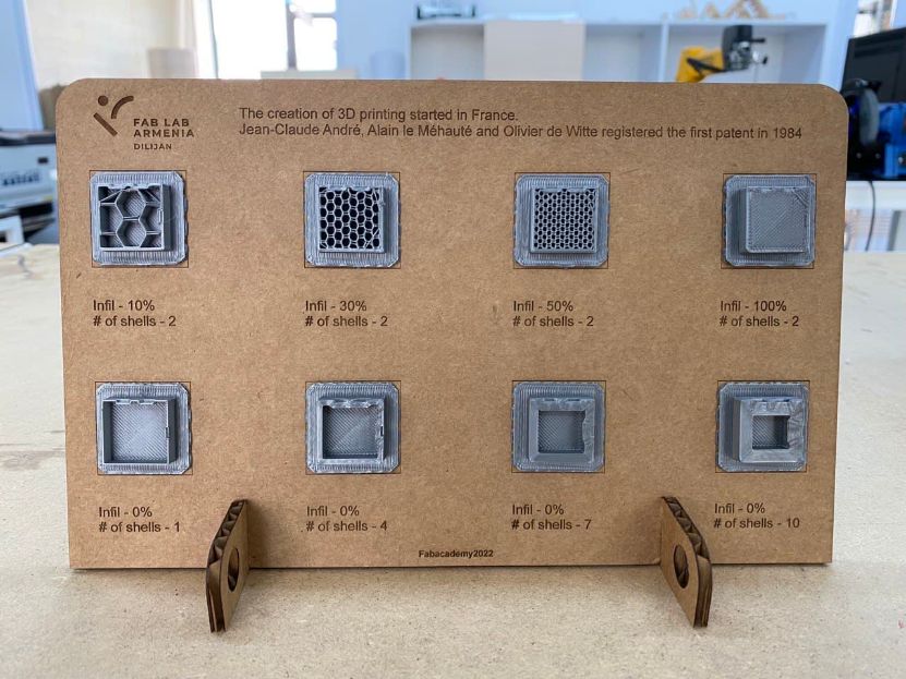
In this assigment I learnt a lot about some of the principal parameters of printing like:
Shell: That is the deposit material that encompasses the center of a printed object.
Infill: That is deposited material that encompasses the outside of a printed object.
You can find more about it in this website of MonroeEngineering.
For testing the printer limitations we used a very funny way to do this.
We used the design of Maker’s Muse who is a Youtuber.
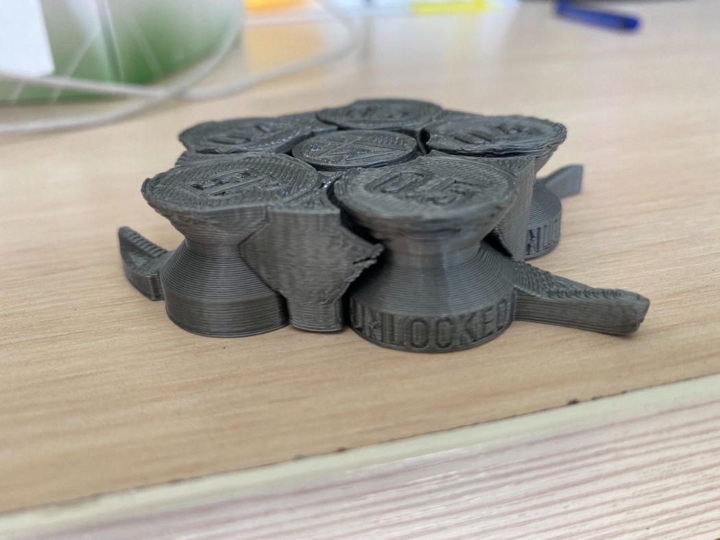
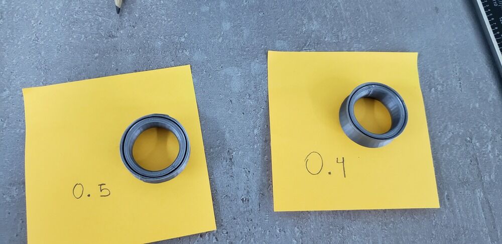
So for our case, we used the Makerbot Replicator 2 that printed this figure:
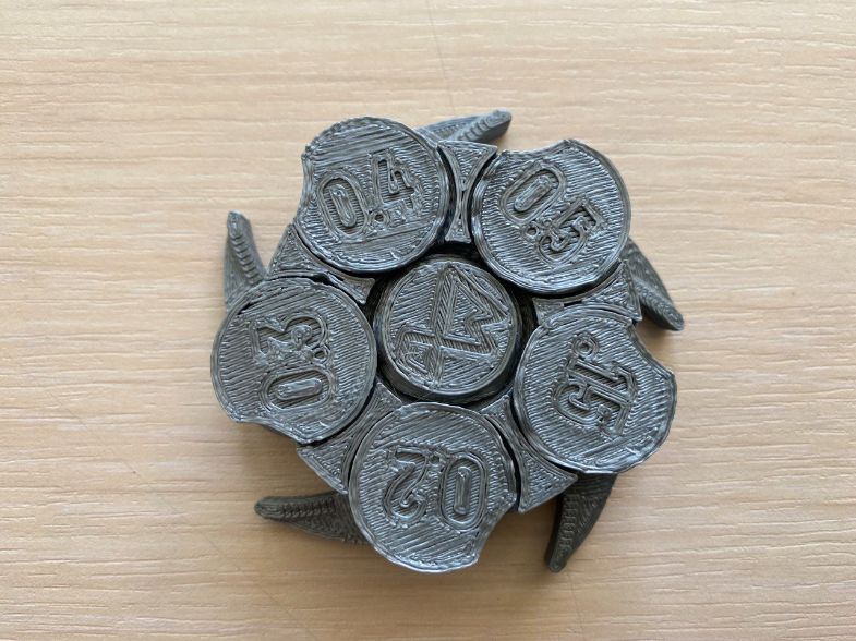
This test consist that those “claws” are a type of “valve”. So if they can unlock, the printer has the property of working with those numbers.
The numbers shown in the test are in milimeters (mm)
The numbers go from 0.5mm , 0.4mm , 0.3mm , 0.2mm until 0.15mm
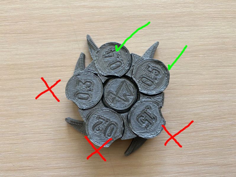
You can see that in this test, MakerBot2 was able to open only until 0.4mm valve, or better explained, MakerBot2 is able to work until 0.4mm gap.
We also used an Ender 3 3D printer to see the difference with MakerBOT, and the results were completely different.
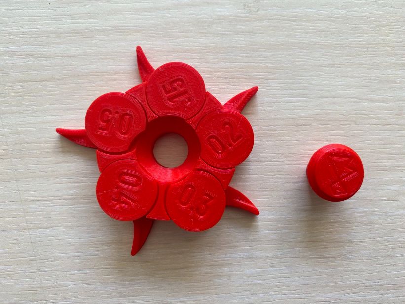
It even opened a secret compartment that we didn’t even know that only opens when all the valves are open!
This means that Ender 3 is able to work with gaps up to 0.15mm
2. Individual assignment
This is my first time working with a 3D printer, so what I made is a simple but interesting accessory that should not be subtractive.
What does it mean that something is subtractive?
Well, according to the website ALL3DP means that:
- subtractive manufacturing is any process in which parts are produced by removing material from a solid block to produce the desired shape.
Knowing this, I have to create a single one piece that must not have separate pieces.
2.1 3D model design and print
It was time to begin with the design. For this, and as it was my first time doing this, I got inspiration from one of the previous designes of my instructor Babken. You can find more about him in his website.
Now that I have an idea from where to start, I wanted to design a ring that has some movement in the outside, so you can play with it when you are bored.
2.1.1 Design
I started whit measuring my finger.
For this I thought in a simple method with maskin tape and a ruler to measure the diameter of my finger.
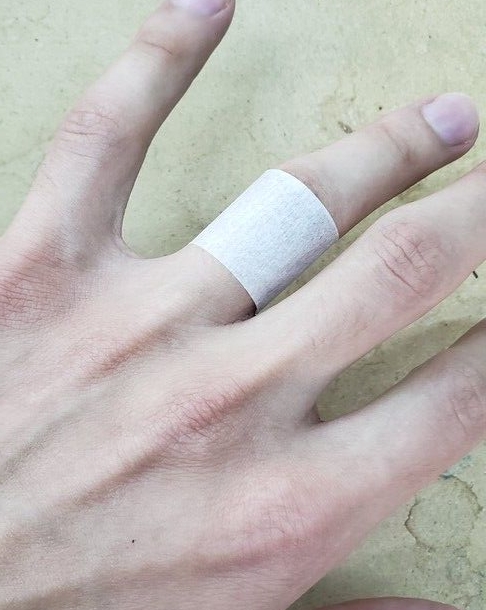
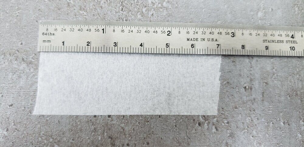
This method is not accurate and exactly, so instead of that, my instructor gave a better idea about using a Fractional Caliper.
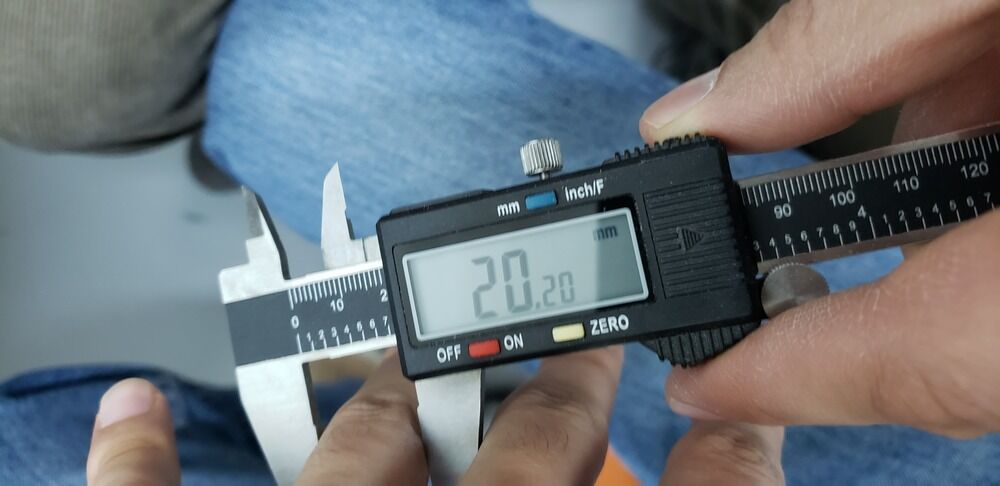
This value of 20mm is the diameter, the radius by 2 (2*R)
So it was time to work in FreeCad:
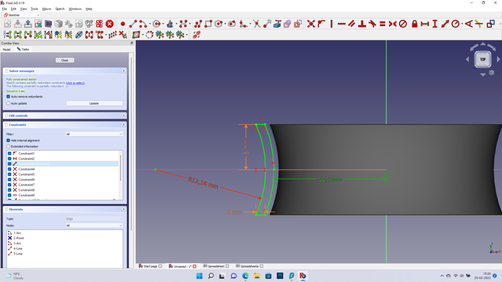
I started designing the inside of the ring adding two arcs
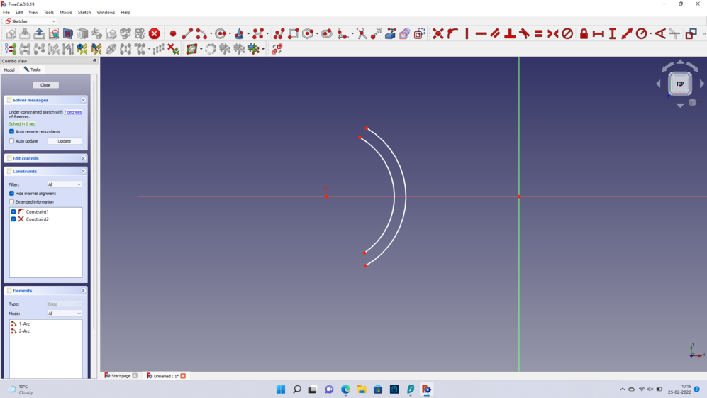
As the diameter of the finger was 20mm and this is only the half of the distance of the ring from the center, I will need to put the half of the value of the diameter from the centre. This is 10mm
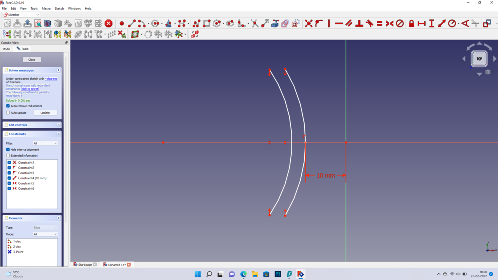
Next, to work more precise, I will create some parameteres, such as:
- Ring Radius
- Arc Radius
- Thickness of the ring
- Height of the ring
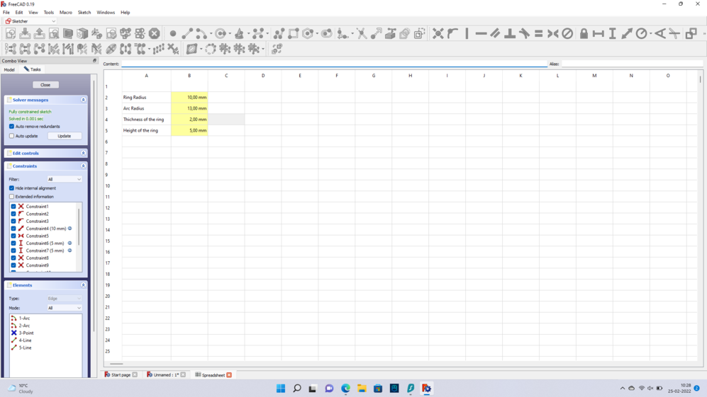
Putting all the parameters, finnaly, I have something like this:
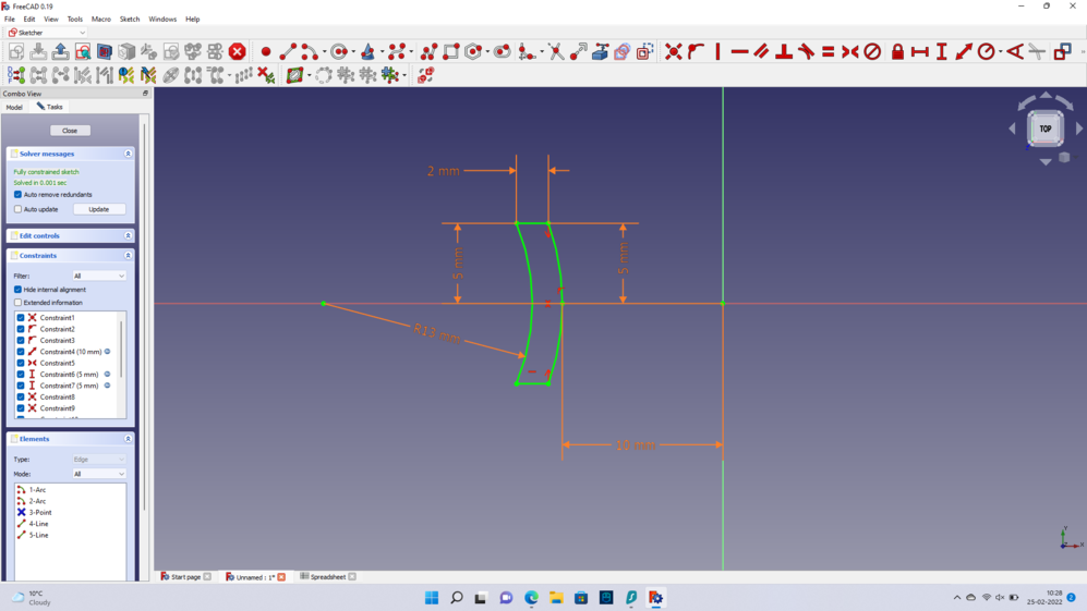
Notice that ther radius of the arc is merely a parameter and does not affect directly the ring. It is just for having a guide for the shape of the ring
Then I used the Revolution paremeter in the toolbar of FreeCAD in the section of Part Design, I made the figure round
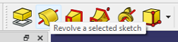
So I ended up with something like this:
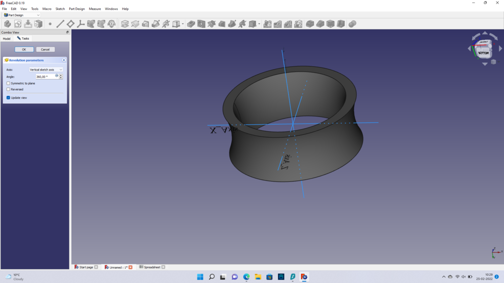
After this result, that looks like a ring, I wanted to create the moving part that will encircle the Inner ring.
We called the outside ring “Antonio”.
Having worked with the Inner ring I did the similar calculations. Only that this time, for making the ring to spin, we needed to count the accuracy of the machine. If you go to Fab Academy Dilijan here, you will find that our machine Makerbot Replicator 2, can work perfect with numbers from 0.4mm to above.
So if I had from the center to the very last edge of the Inner ring 12mm, this time I need to have 12.4mm
So our ring eventually will spin.
If I would have put 0.3mm the ring would not spin, due to the lack of precision of the machine, the parts would get attached.
Having now the outside ring, or Antonio, I did the same steps for making the figure round. Part design and after it Revolution parameter.
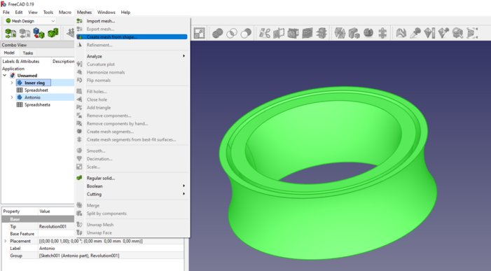
Now we want to print this figures and for it we need to pass them through a process called “mesh”.
By words of the page FreeCAD:
The word “Mesh” is normally used to refer to a Mesh MeshObject (Me, a type of object that defines 3D data but is not a solid “Shape”. Meshes are very simple objects, containing only vertices (points), edges and triangular faces. In general, they are easy to create, modify, subdivide, and stretch, and can be passed from one application to another without any loss of detail.
So I will use this tool here called “Create mesh from shape…”:
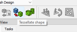
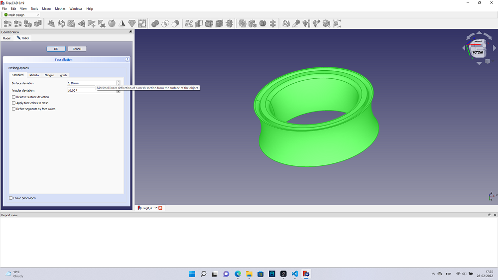
After this I clicked on “*tesellate shape”
This led to a screen that for now it doesn’t matter the parameters, just click on “OK”
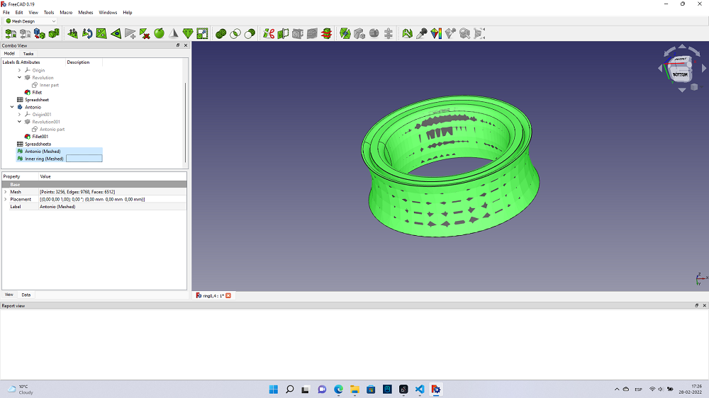
Then you will have two “meshed” figures. In this case is
-
Antonio (Meshed)
-
Inner Ring (Meshed)
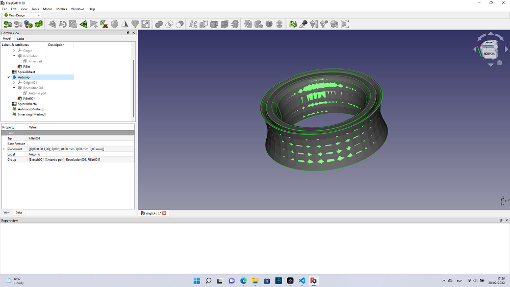
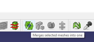
Choose both with ctrl + left click
and click on this icon in the toolbar
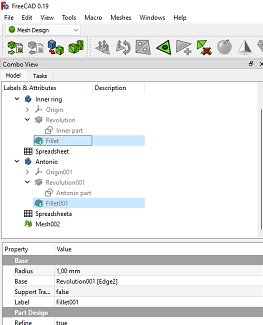
Once it’s ready, you will have one solid figure. For my case it’s called Mesh002
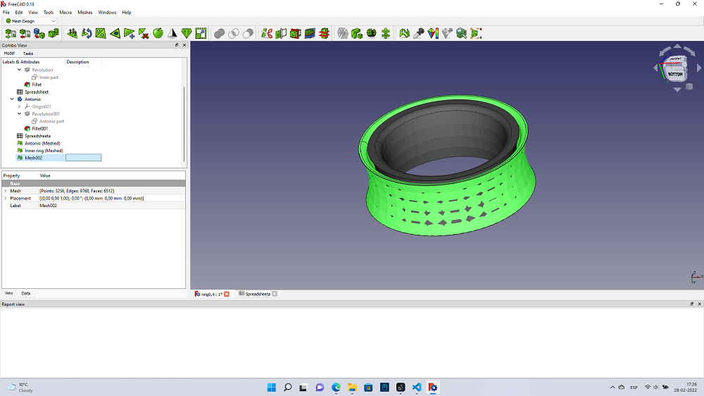
Tip Remember that when you select a figure you can press “space bar” to make it invisible. So it won’t bother you in your work.
Like this:

You can also play with the Fillet option, that will make the borders of your figure smoother, but this is optional
2.1.2 Printing
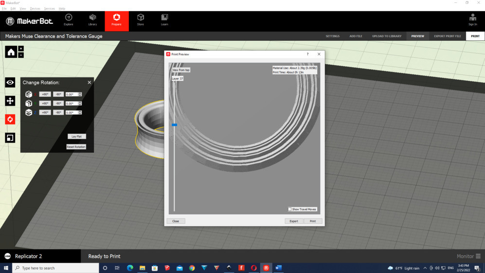
For printing it, I used the software that comes with the 3D-Printer.
I just exported as an stl file and opened it in the program.
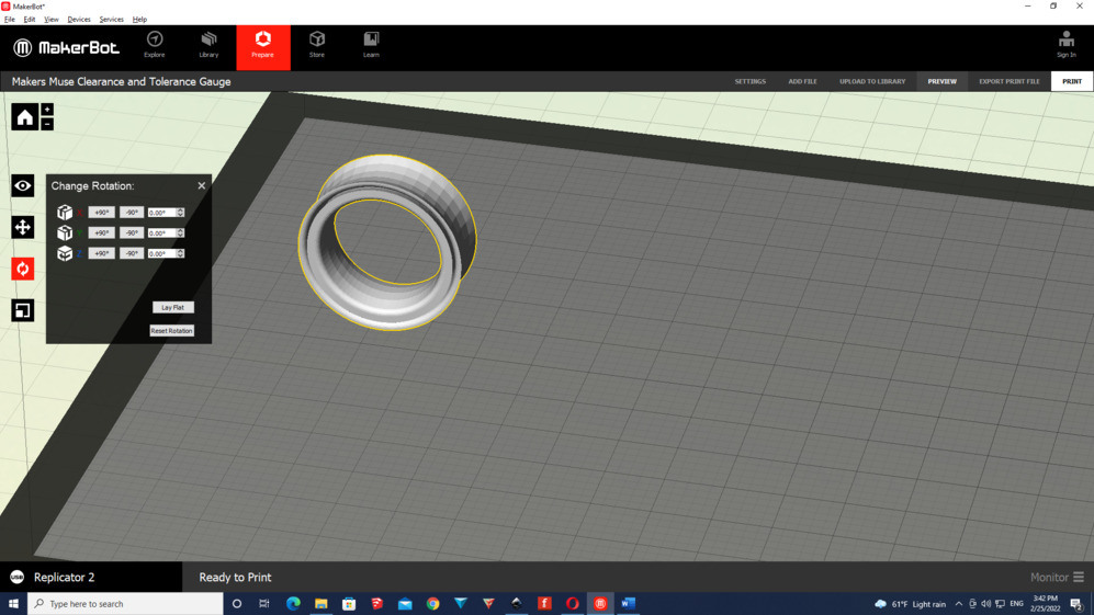
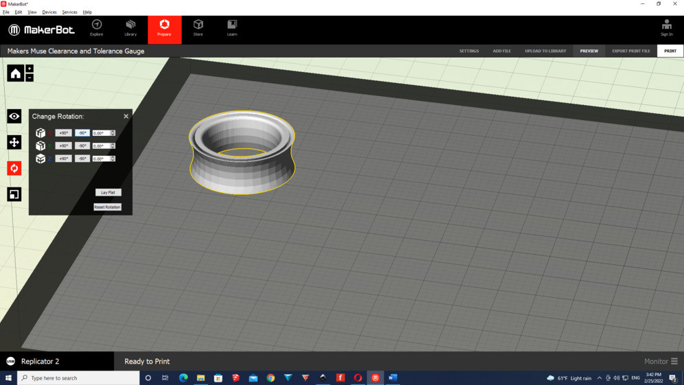
As the figure was in a bad position I have to press on the -90° option to make it flat with the surface.
On the parameters I tried to play a little bit with the shells of the figure
I figured out that the number of shells will not change if I increase it more than two.
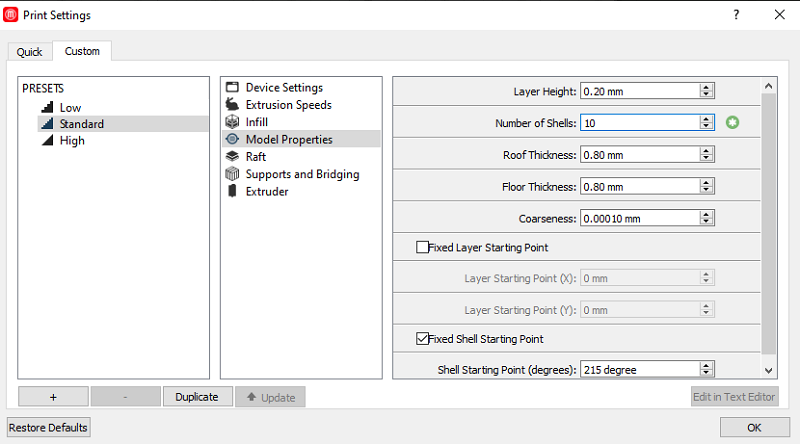
But as it didn’t matter if I increase this number, because the shells will be two even if I increase it to 10, I left it as two.
You can see in this image the number of shells even if I put 10.
The process of printing was a success. It took around ten minutes + the time that I waited for the machine to got heat.
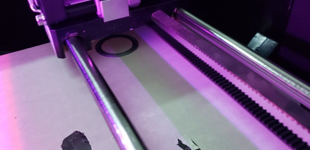
The result was awesome, it fits not that perfect on my finger, and sometimes it gets stucked
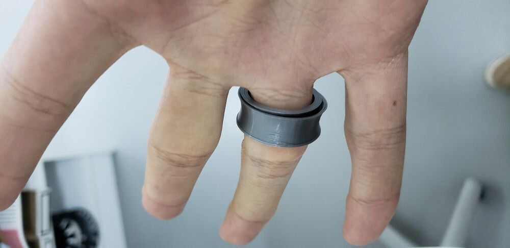
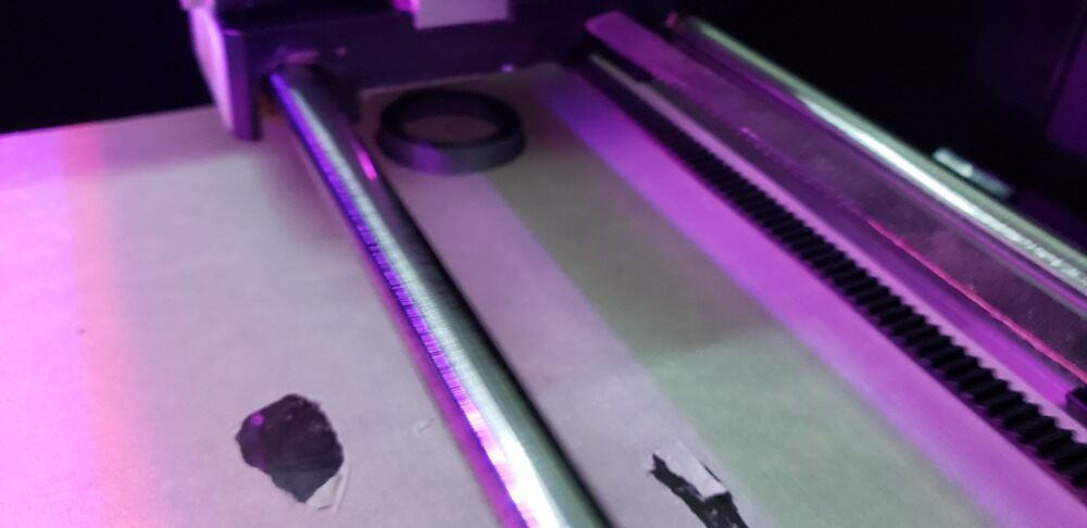
If you remember I made one with a gap of 0.4mm....Well I made another one with a gap of 0.5mm just for testing it.
2.1.3 3D scan exercise
For this task I’m using the app 3D Live Scanner free version for Android Mobiles.
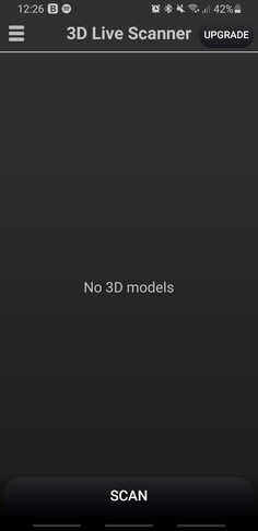
The first thing that I had to do inside the app was to allow access to the microphone and data-files. So I ended with a menu like this.
When I clicked “Scan” button, another menu was opened.
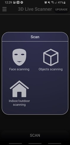
After I clicked on “Objects Scanning” a message was shown:
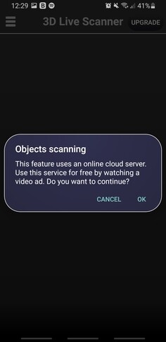
Basically as it was a free software I had to watch an advertisement for 30 seconds. After the video I started to scan a cookie Oreo that I had.
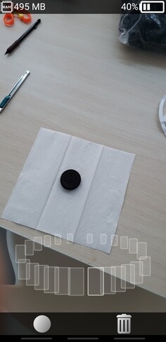
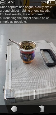
In the up-left corner you can se the RAM that is using the app in the moment and in the upper-right corner the current battery of your deivce.
The down-left corner was for starting the scanning and the down-right corner was for eliminate the progress of your scan (if you take a bad angle of the figure for example).
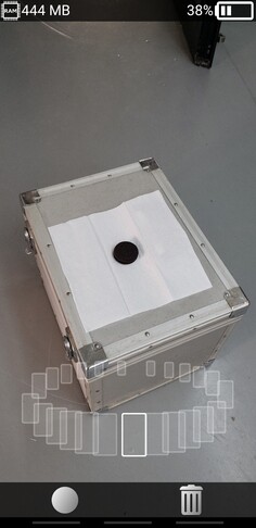
Once I pressed the down-left icon (the one that looks like a white circle), I had to move slowly around the figure that I wanted to scan.
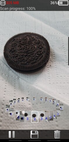
Getting the 100% of the scanning progress I clicked on the save icon that appears once you are scanning the figure.
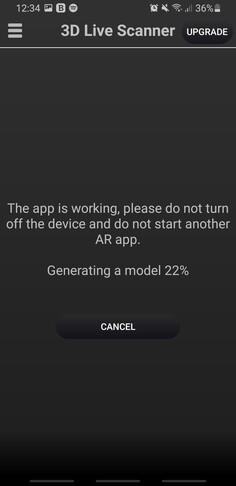
When I clicked on it I was redirected to a menu like this:
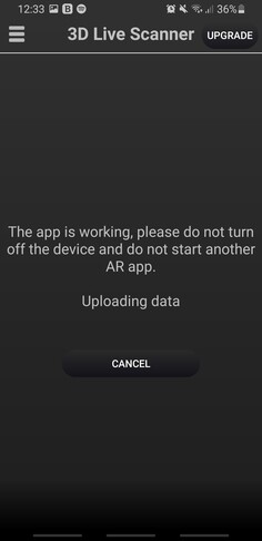
I waited around 5 minutes to unfortunately had an error.....

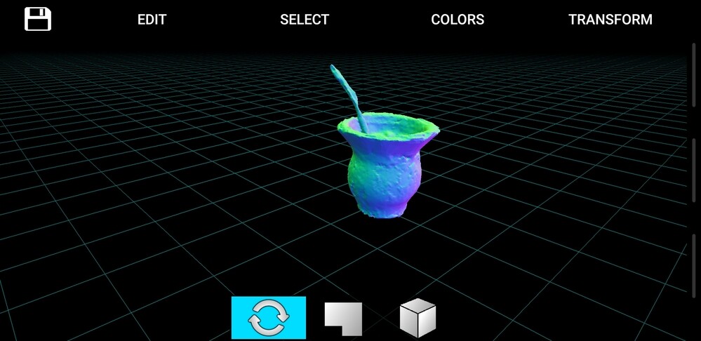
Looking to this failure I decided to work with a more robust and solid figure. That’s why I wanted to print my “matera” a latin-american cup. Doing the same steps as before....
Greatfully I ended up with a fantastic result:
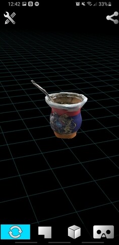
And here is the figure with the solid model:
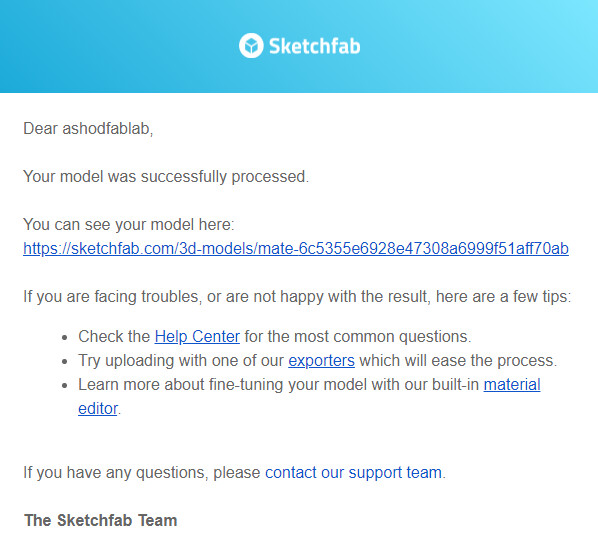
For uploading and have the model on internet, first we need to create an account in SketchFab
After signing-up you will recieve a notification to your email like this:
Once your accont is activated you can go to the aplication again, and click on the “share” button in the upright corner.
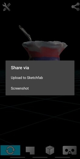
Click on “Upload on Sketchfab”.
If you click on “Screenshot” it will only take a picture and you won’t have the file.
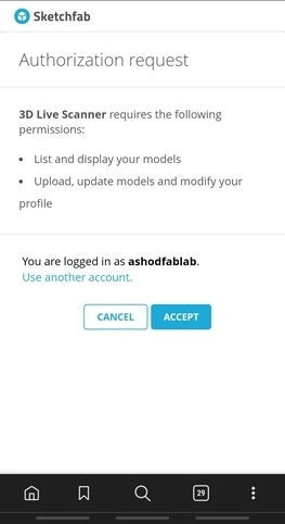
Log-in with your account that you created previously and authorize the aplication.
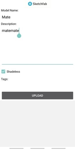
Now write the name of your model, and the description and click on “Upload”.
The option “Shadeless” is by marked by default so I’m not touching it.
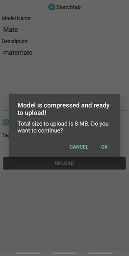
After you had clicked on “Upload”, you will recieve a notification with the size of your model (In this case is 8mb) and with a message that is ready to upload.
Click on “Ok“
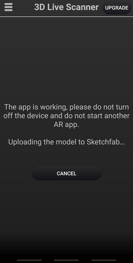
After it, you will be redirected to the application again with the following message:
2.1.3.1 Model
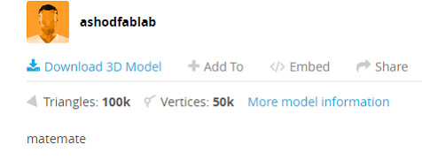
Once is done you can check the model in the webpage of SketchFab:
My_Model
One cool thing that I noticed is that in the webpage you have the amount of triangles and vertices of the model. In my case I have
- Triangles: 100k
- Vertices: 50k
2.2 Conclusions
This week opened up my mind about when to use a 3D printer and when not.
I made my research about the benefits of using this method of printing and what I discovered, mostly in the website unleashedsoftware, is that the main benefits of using the addivite manufacturing is:
Benefits
Material waste reduction
Manufacturing and assembly
Inventory stock reduction
Options that with the extrution manufacturing are unable. (movil parts)
Limitations
It’s slow
Post processing (surface finishes and dimensional accuracy can be of a lower quality compared with to other manufacturing methods).
Additive manufacturing is a very good way of prinitng and seeing your creations become real. The only big problem that I see, it’s the quality and precision issues that the current machines present.