4. Electronics production
Group Assignment Page
Click on this link to go to our group assignment web-page.
I made the cuts with the 1/64 end mill. Which, it can’t go below 0.016inch or 0.4064mm.
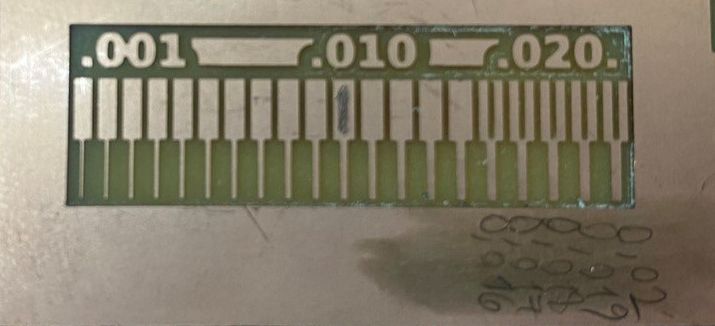
From this, I learnt that at the moment of working with wires, the gap between both, must not go below 0.4mm, otherwise, the end mill won’t be able to create the gap.
1 Getting the resources for the PCB
I had no idea how to solder, create a chipset, or even programming a chipset. So that I followed the instructions given by this webpage:
First, I read the manual for the machine Roland Srm-20.
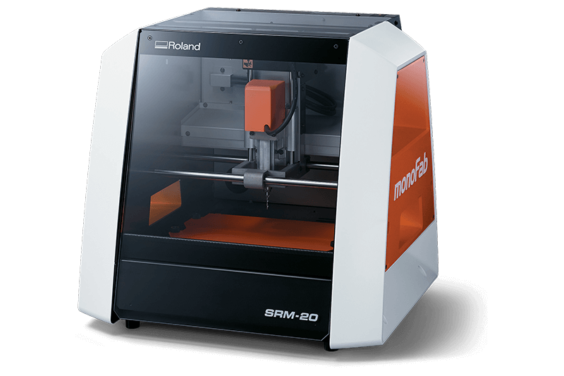
After getting some knowledge about it, and with the help of my instructor, I started to follow the steps of the instructions that I mentioned above.
What I did first, was to download the file of the traces and the interior.
Once I downloaded both, I went to Brian’s Website, and I followed step-by-step what he did.
2 Using Modsproject
Unfortunately, fabmods was not available for this year, but the second option was to use the page of the MOD.
Now as well, if the first link doesn’t work, you can have the other Mods, that for my opinion is more user-friendly.
These websites can be a little bit tricky, but once you understand them, they can work very well.
| On the website right-click on the screen and select “Programs”. |
|---|
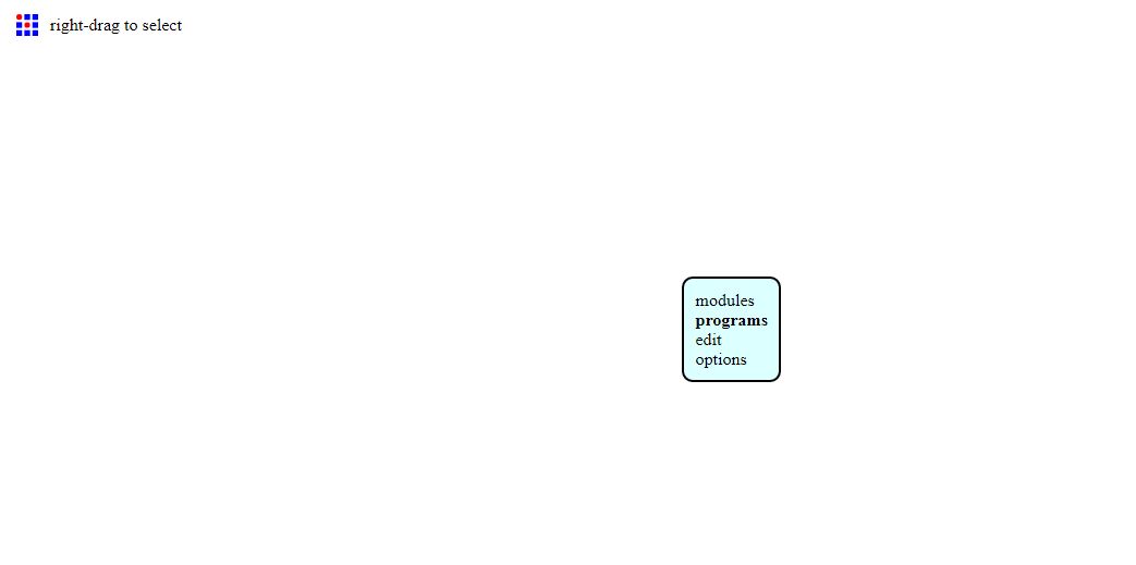 |
| Then click on “Open Server Programs”, and find the correct program for your machine. |
|---|
 |
| In my case, I was going to work with G-code, using .png files. |
|---|
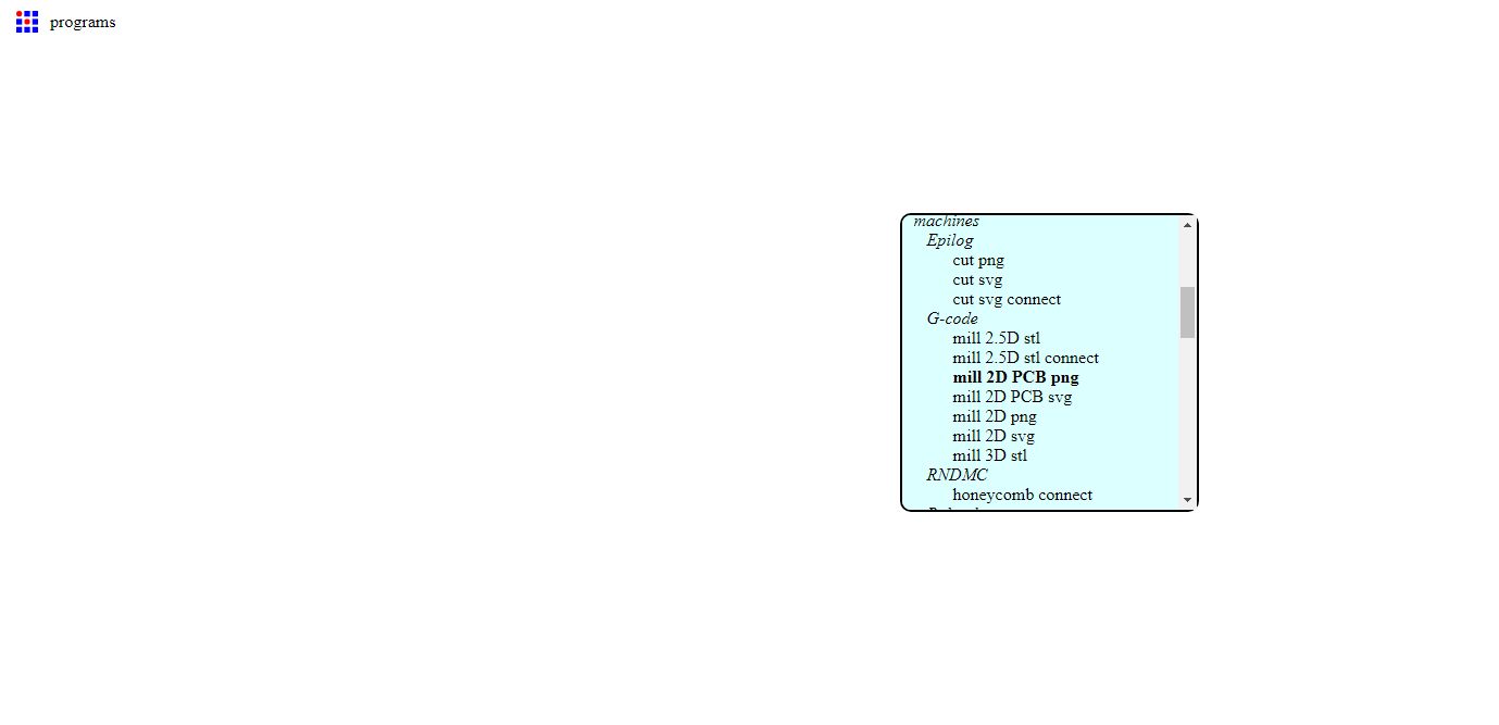 |
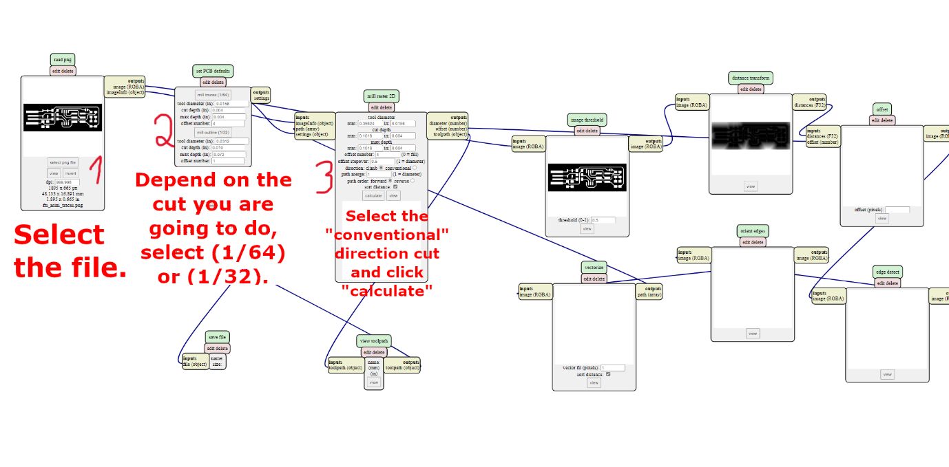
1) Click on “Select png file” and select the traces file first.
This is because it’s helpful to do the traces first, and then cut all the PCB
2) Now, select Mill traces (1/64), this is because to make the traces requires a more delicate end mill.
3) The last part is to click on conventional direction, this is the type of cut I will explain it later on this assignment (Number 5. “Difference between Conventional and Climb”).
After it, click on Calculate.
Important Observation
Here, I need to mention that the black parts of the image that you will upload are the parts that are going to be cut. The white ones will be untouch.
| These are the steps |
|---|
 |
| Another window will be open and you will have to save .nc file. This file you will have to open with the software of your machine. |
|---|
 |
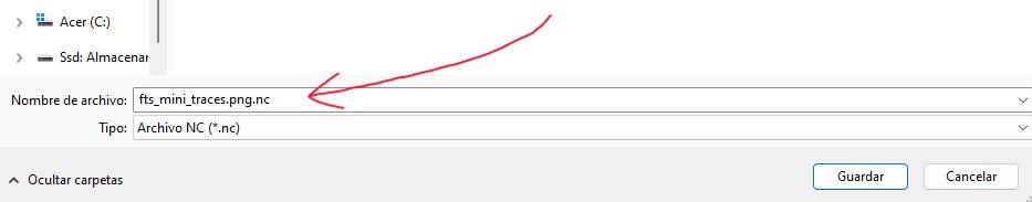 |
| You can clearly see that the file that it has downloaded is in G-code, because when you open it it shows the following: |
|---|
 |
Before cutting:
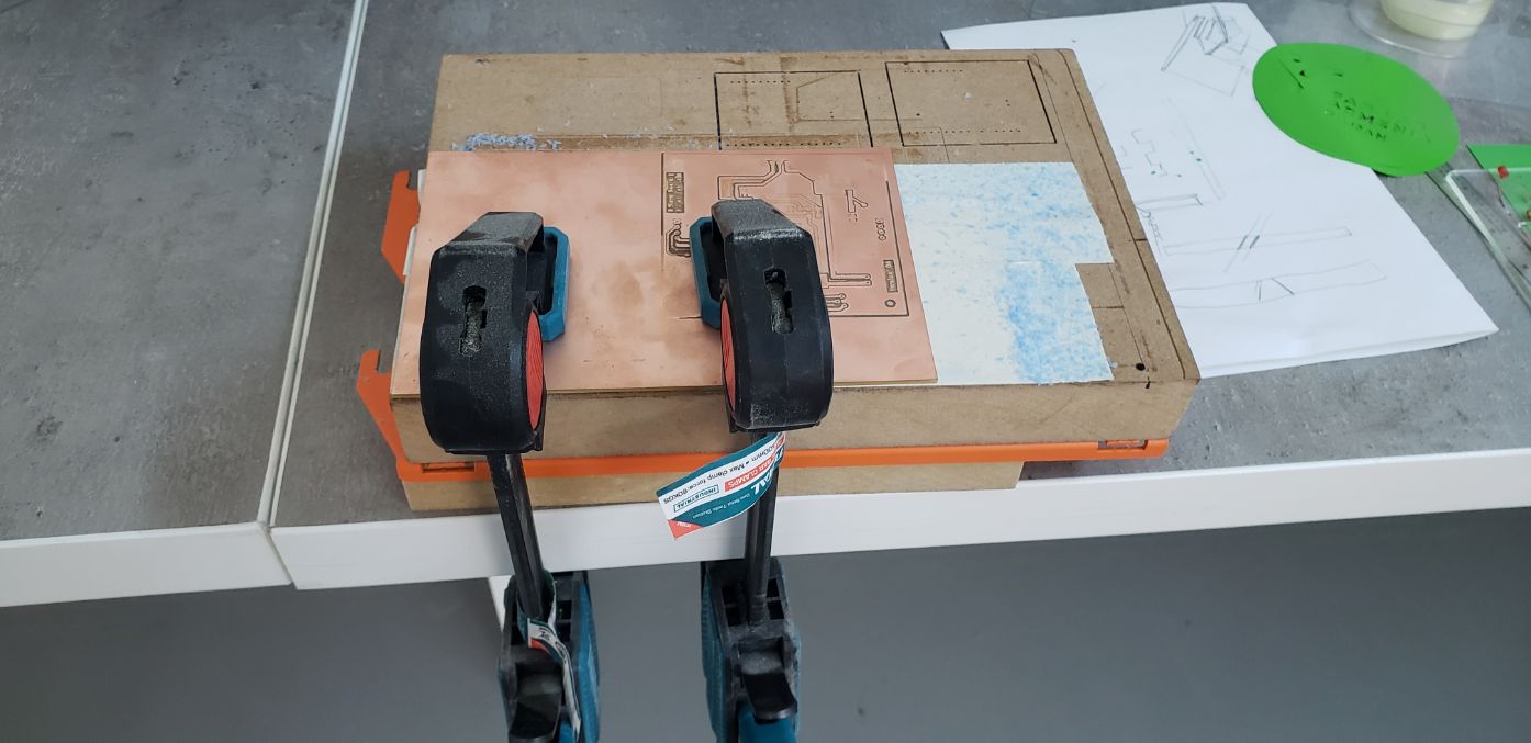
My recommendation to attach the copper plate into the Roland orange metal plate, is to do the following:
Remove the Roland orange metal plate (unscrew 4 screws at sides), and put some double-stick tape on it (is better if you have a wood working table on the orange plate).
Then with the help of some clambs, tighten the copper plate into the orange plate.
I recommend as well to put something under the orange plate to not breake it, as in the bottom, it has a small edge.
Something like this:
After this, attach the orange plate to the screws and set everything up.
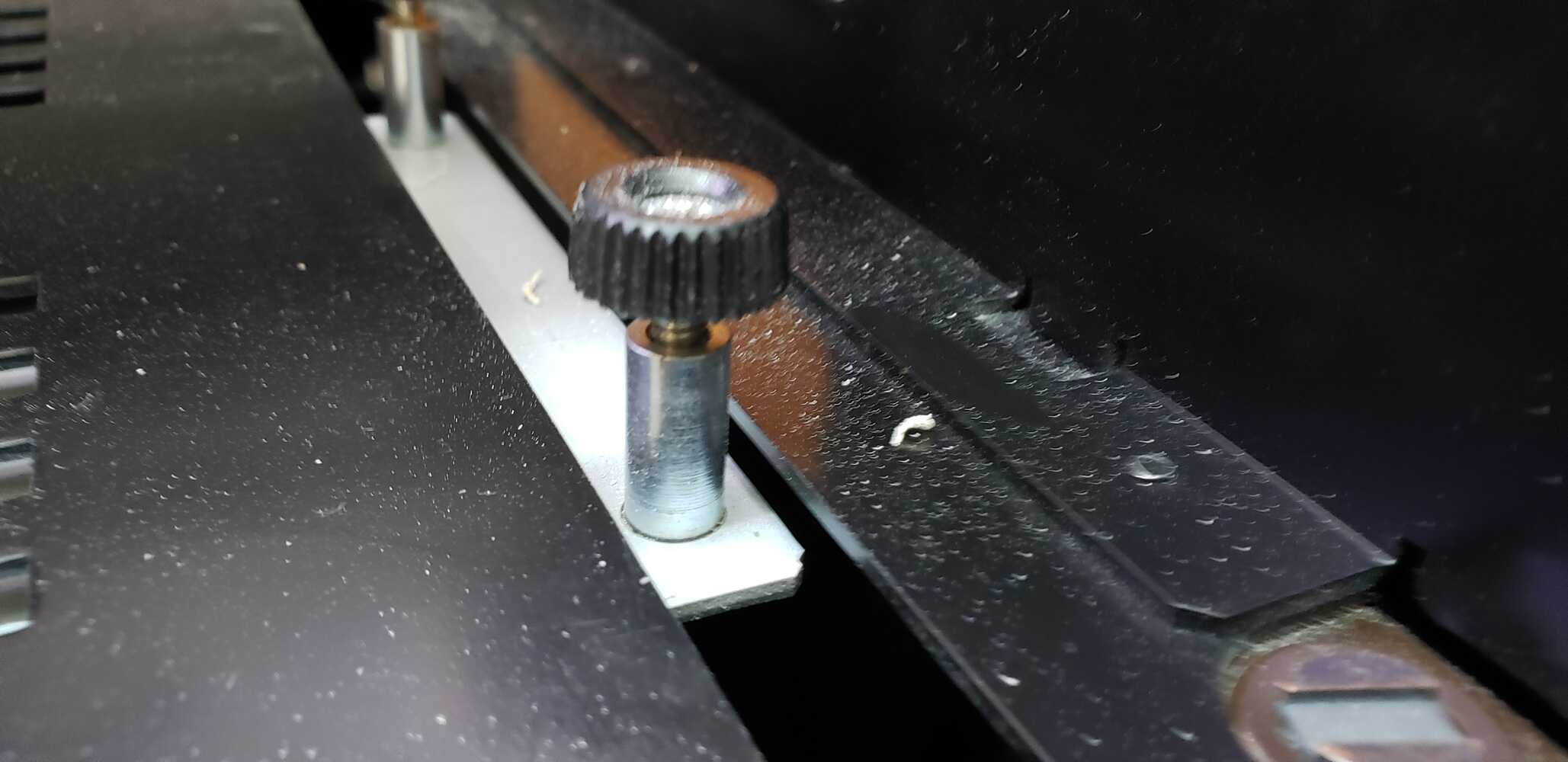
Then, for changing the end mills, you have to use the tool that comes with the machine.
Be carefull to not drop the end mill.
For setting “Z” axis, a good method is to aproximate the end mill to the plate, and with the help of the finger, smoothly let it down until it touches the plate.

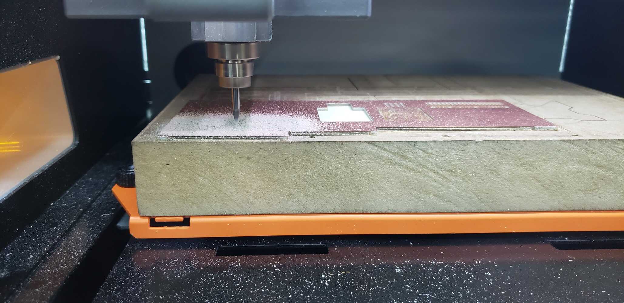
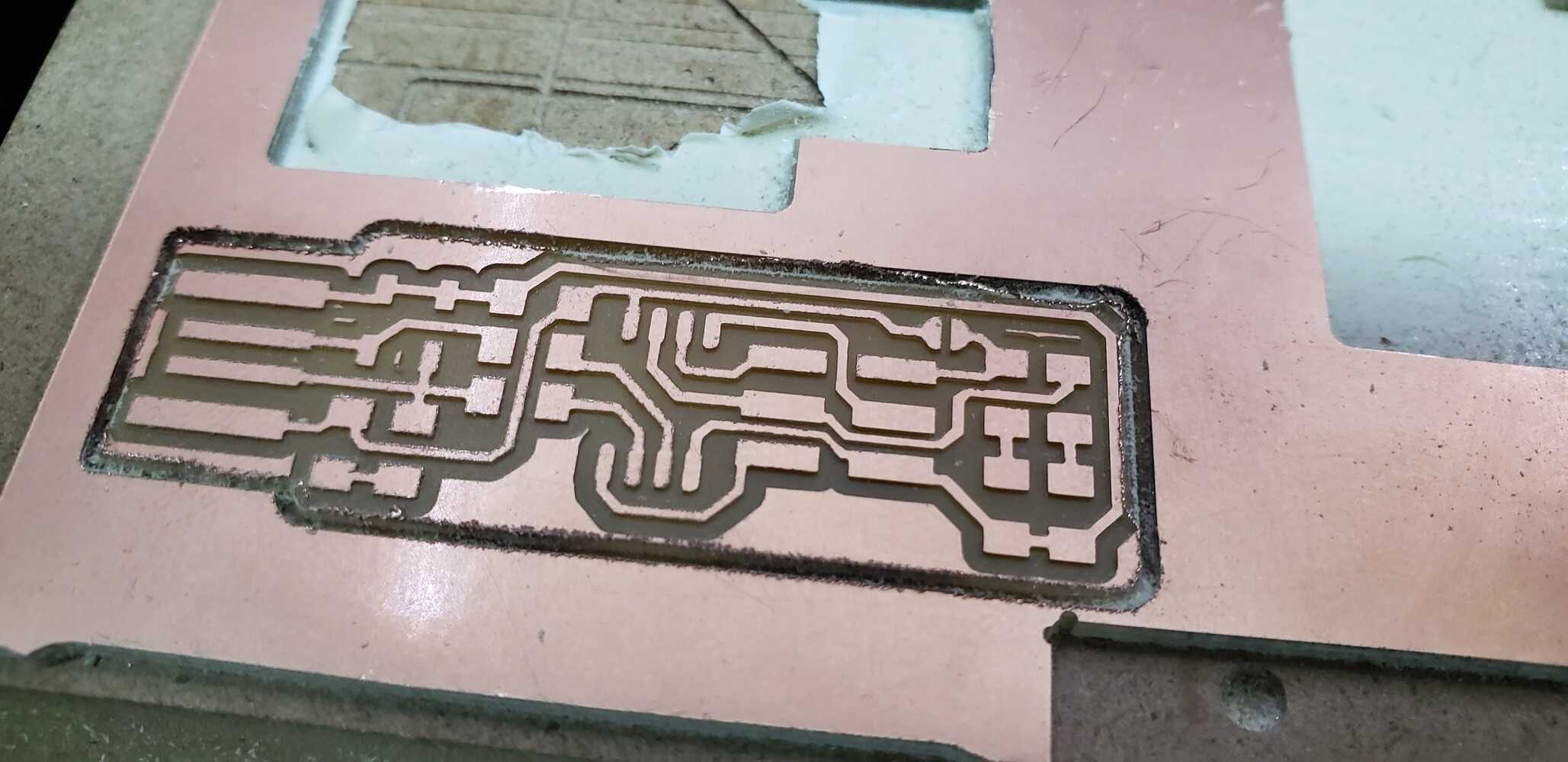
3 Cutting the traces of my PCB:
After this I went to the roland software and I chose g54. I made sure that the g54 was compatible with the g54 that I was working with.
I moved the spindle to the position that I wanted to, and I clicked on origin, to put that spot as the new (0,0,0).
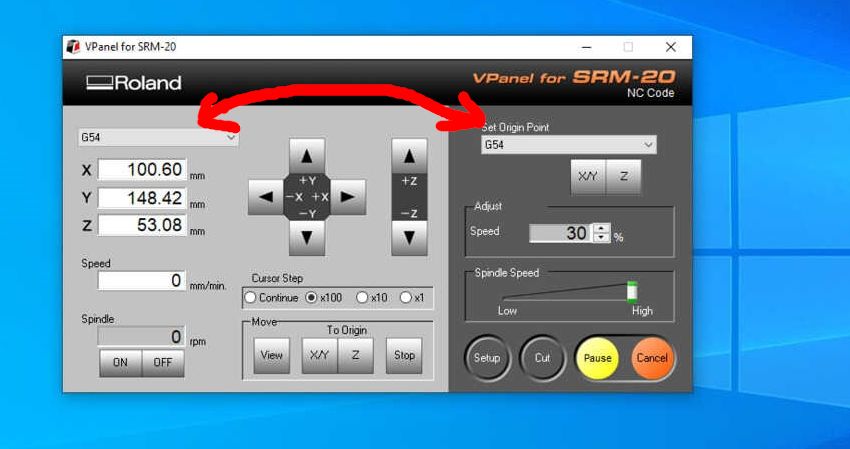
I think there might be some things to explain in the Software which are:
-
1) Cursor Step: This is about the distance which the end mill will travell when you move it manually.
-
2) Move | To Origin:
View: This will place the workbench of the machine in an observable position.
X/Y: This is to move the end mill to a preset X/Y location. Z: This is to move the end mill to a preset Z location. -
3) Set Origin Point: This is to preset the end mill whit the current position where it is.
-
4) Adjust Speed: This is the speed which the end mill will move while cutting.
-
5) Spindle Speed: This is the speed which the end mill will spin.
Knowing this we can continue with the cutting process.
For this, in the Roland’s software, I clicked on
Cut >> Delete All >> Add >> (Select the file that I wanted to cut) >> Output
The machine automatically will start to cut after this.

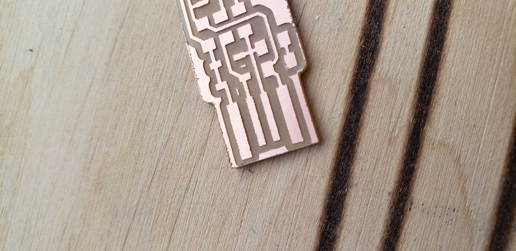
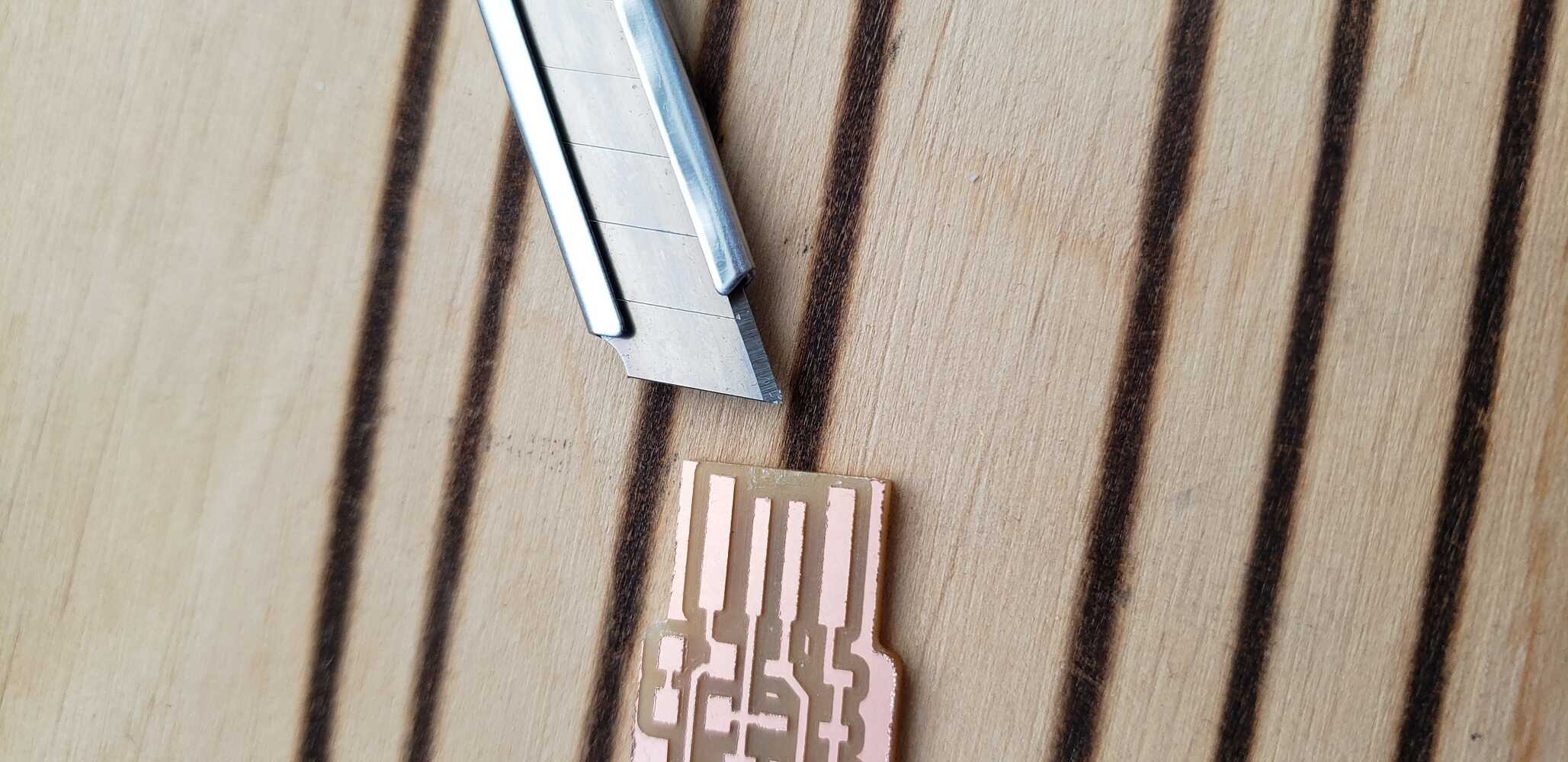
4 Cutting the interior
For cutting the interior I wanted to do an experiment to see how much it will change if I select in the MODS, the climb cutting instead of the conventional one.
So for cuting the interior, what you have to do, is basically the same than with the traces.
Just be careful to select the proper file that you want to cut and pay attention to select the ENDMILL (1/32), because, as this cut is more hard to cut (because you will go deeper) you will have to use a bigger endmill, in this case (1/32).
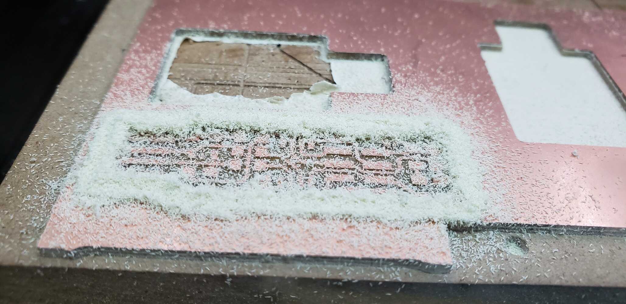
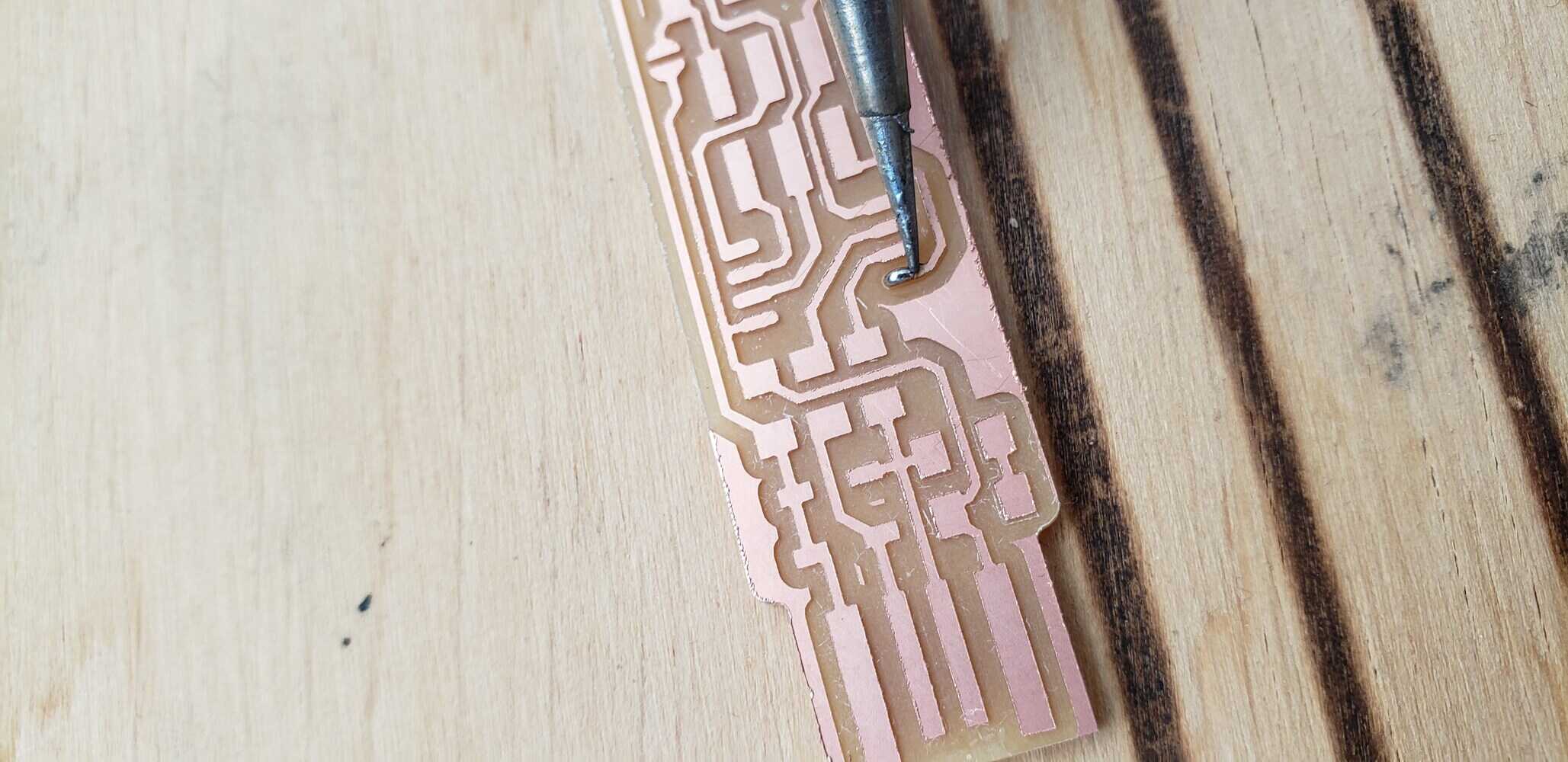
You can see in the last picture that the cuts are not good. This is because the cut was made by climbing direction and not conventional
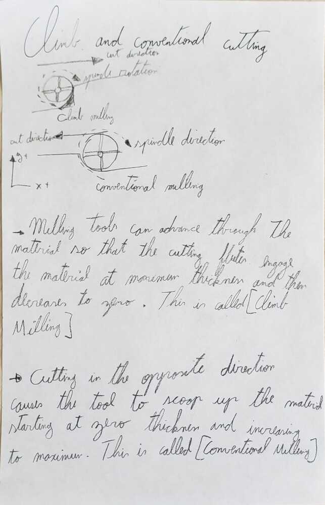
5 Difference between Conventional and Climb
After a deep research and some notes that I made, I finally understood what is the diference:
So, mainly, this are the differences:

6 Soldering
As I didn’t have experience on soldering, my mentor gave me some time to practice with the soldering.
At the beginning I was soldering awfully, but after some training I get the idea of it.
| You can see the illogical amount of soldering material that I was putting at the beginning |
|---|
 |
 |
| But after some practice I could manage to solder “decently” |
|---|
 |
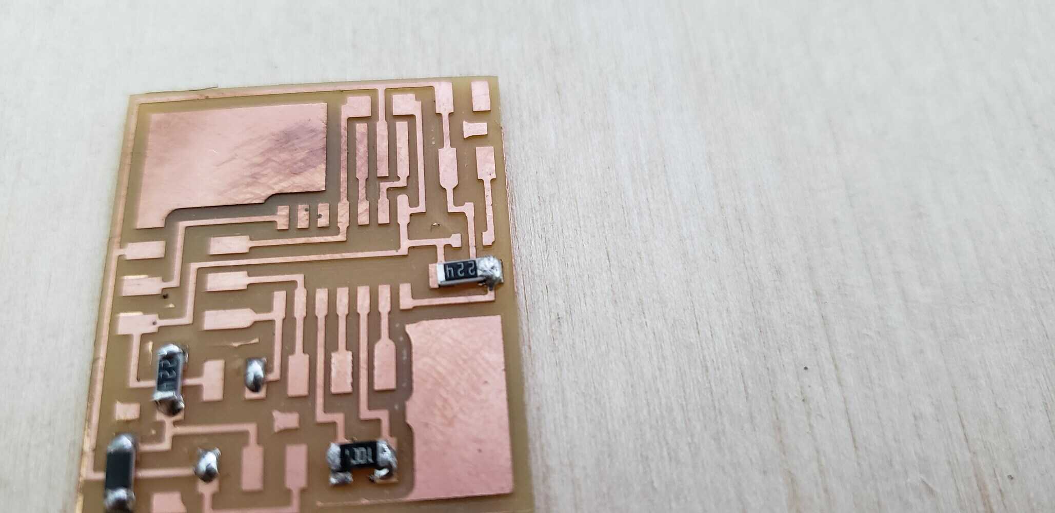
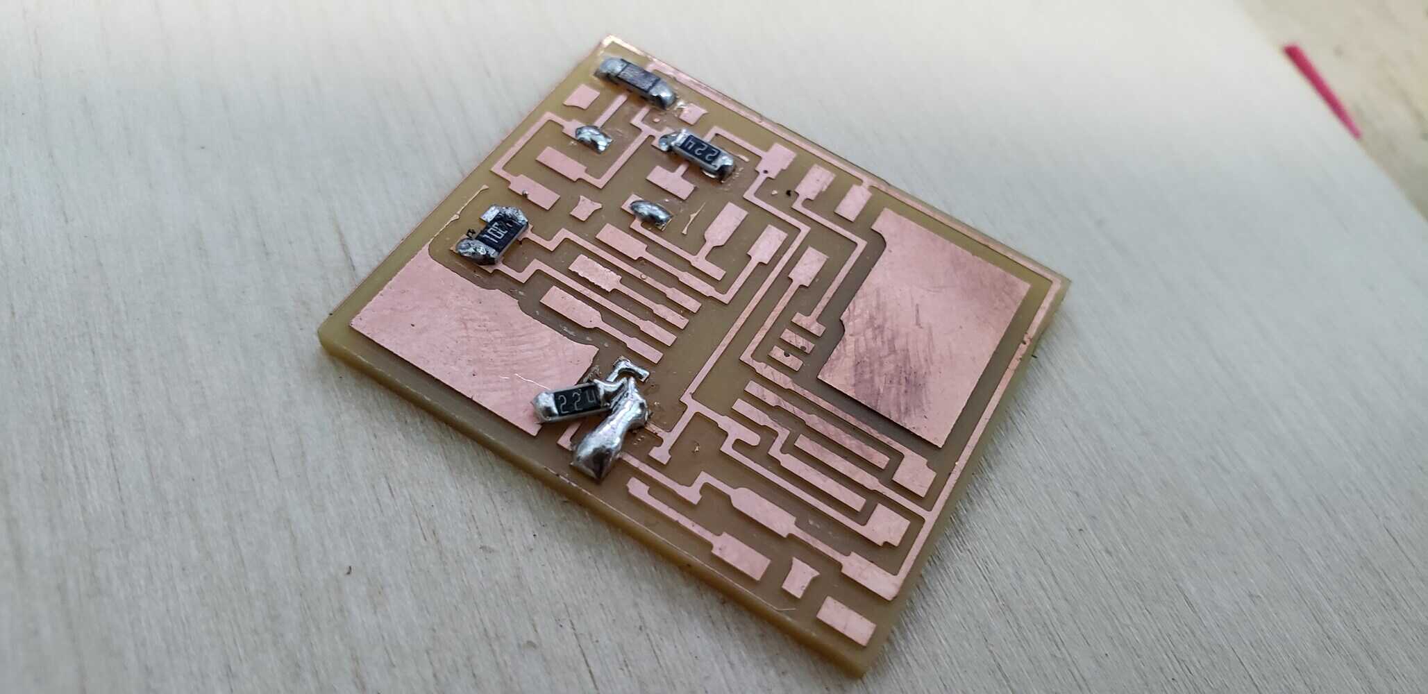
I was ready to solder my PCB:
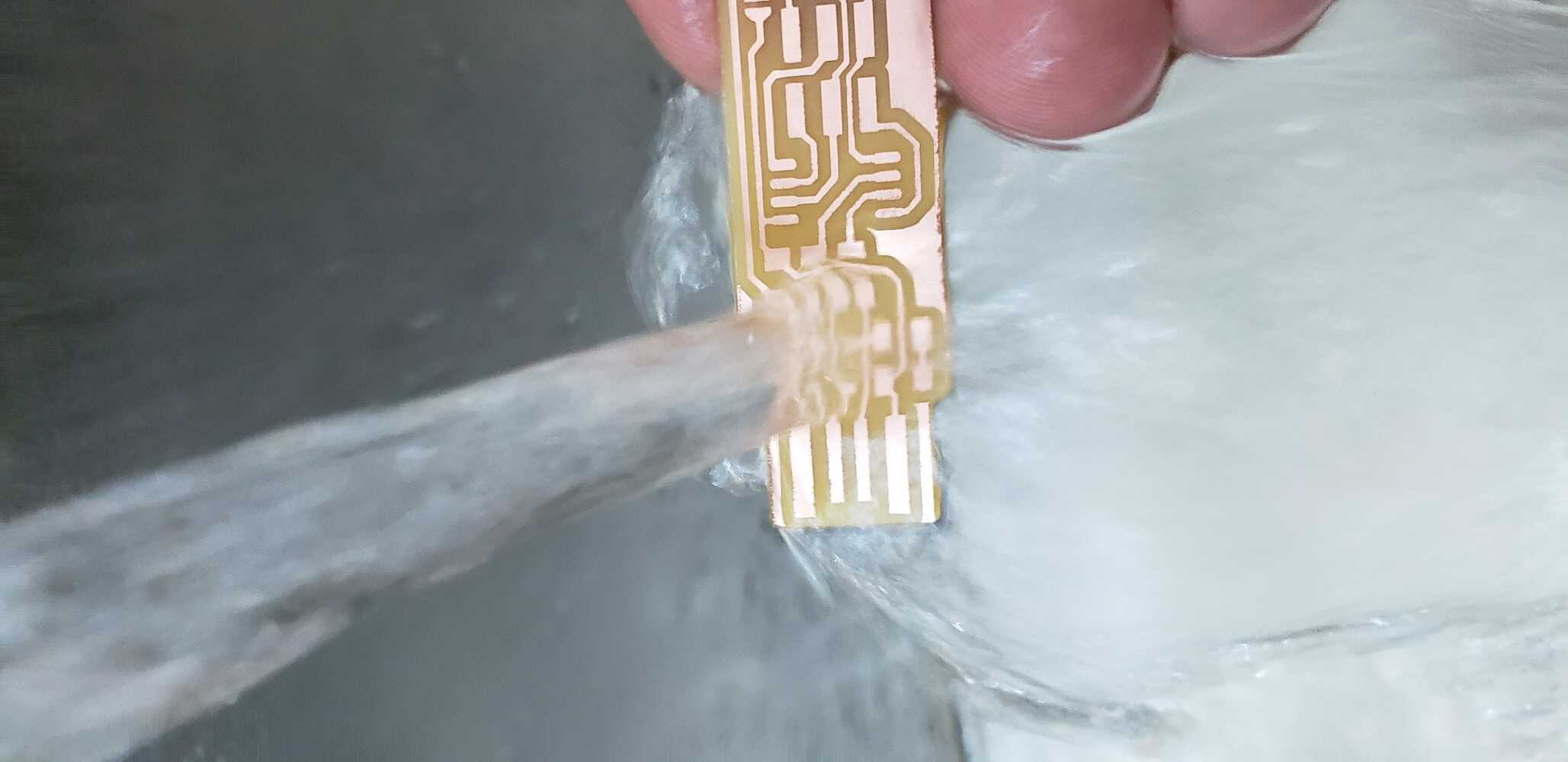
So first what I did was to remove the copper in front of the pads as the documentation of Brian said.
Then I wash it with water to remove any remnant of particle:
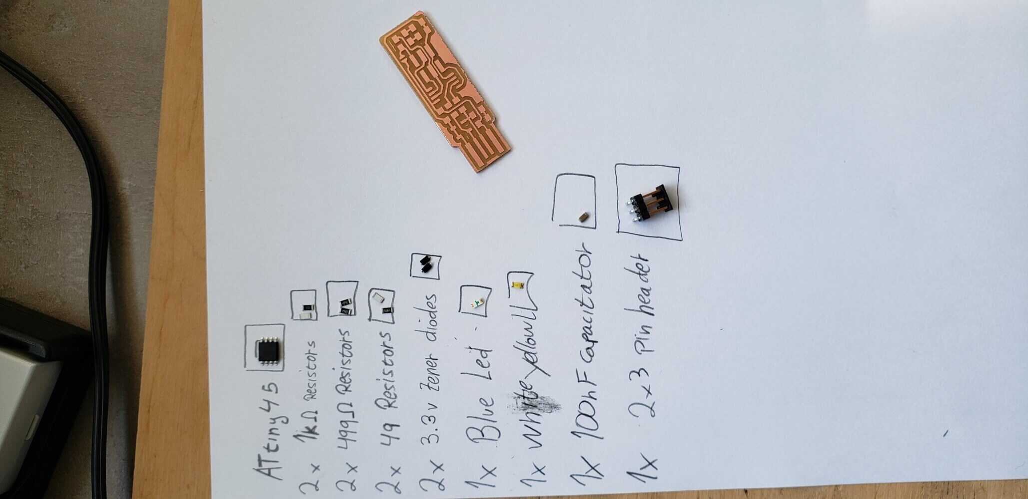
Later, I started to look for the components that I needed for soldering in the boxes.
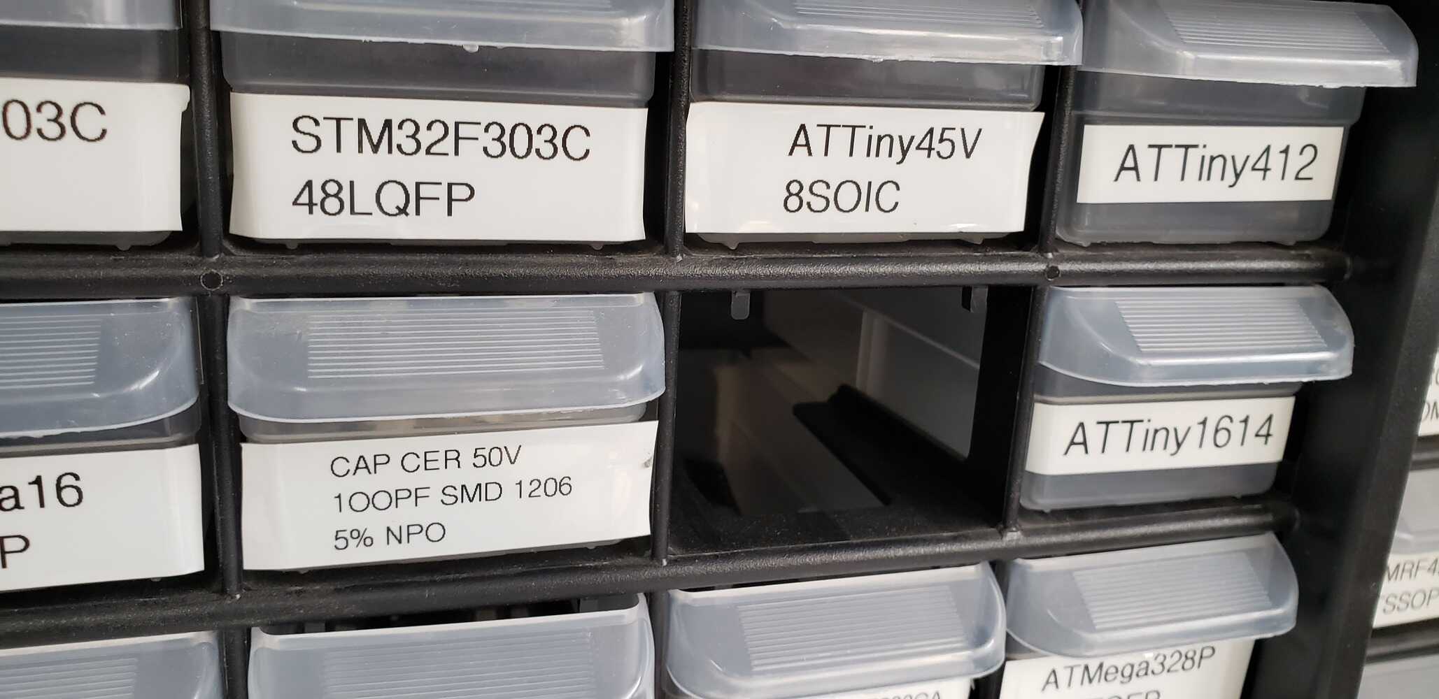
It took a while, but finally I had everything that I needed.
So I started the soldering process.
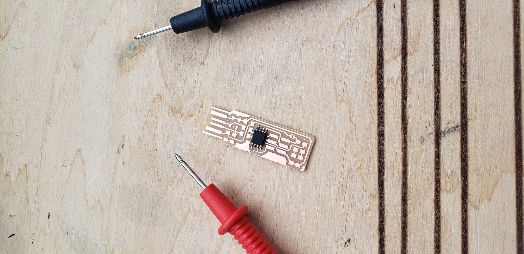
The first component that I solder was the ATtiny 45, and the last one the 2X3 Pin header, because as this component is higher, it can make things a bit complicated to solder.
When I soldered it, I used the multimeter to check if the legs of the microchip weren’t touching each other:
I continued soldering, and of course I had “amateur accidents”:
| Once everything was soldered, I had to create a bridge on the jumper, this is made so the header can be used to program the ATtiny45. It can be a little too hard for me to explain so I will take a screenshot from Brian’s documentation, he explained it better. |
|---|
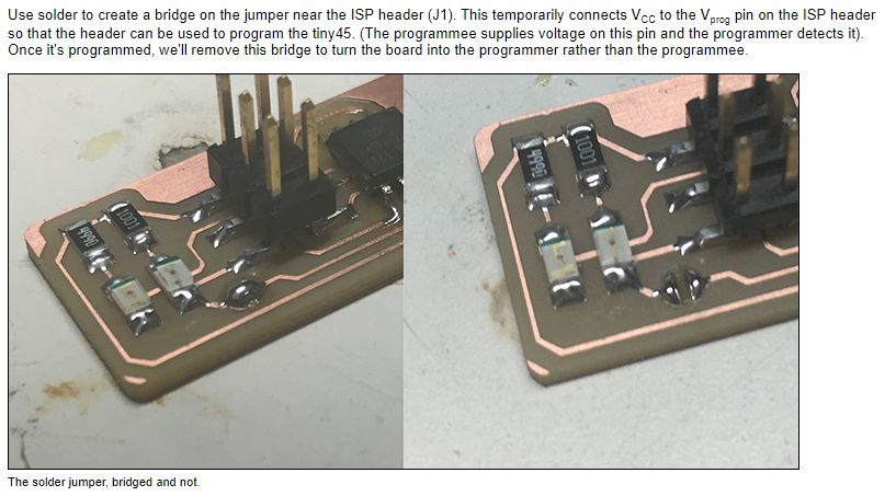 |
| So that’s what I did |
|---|
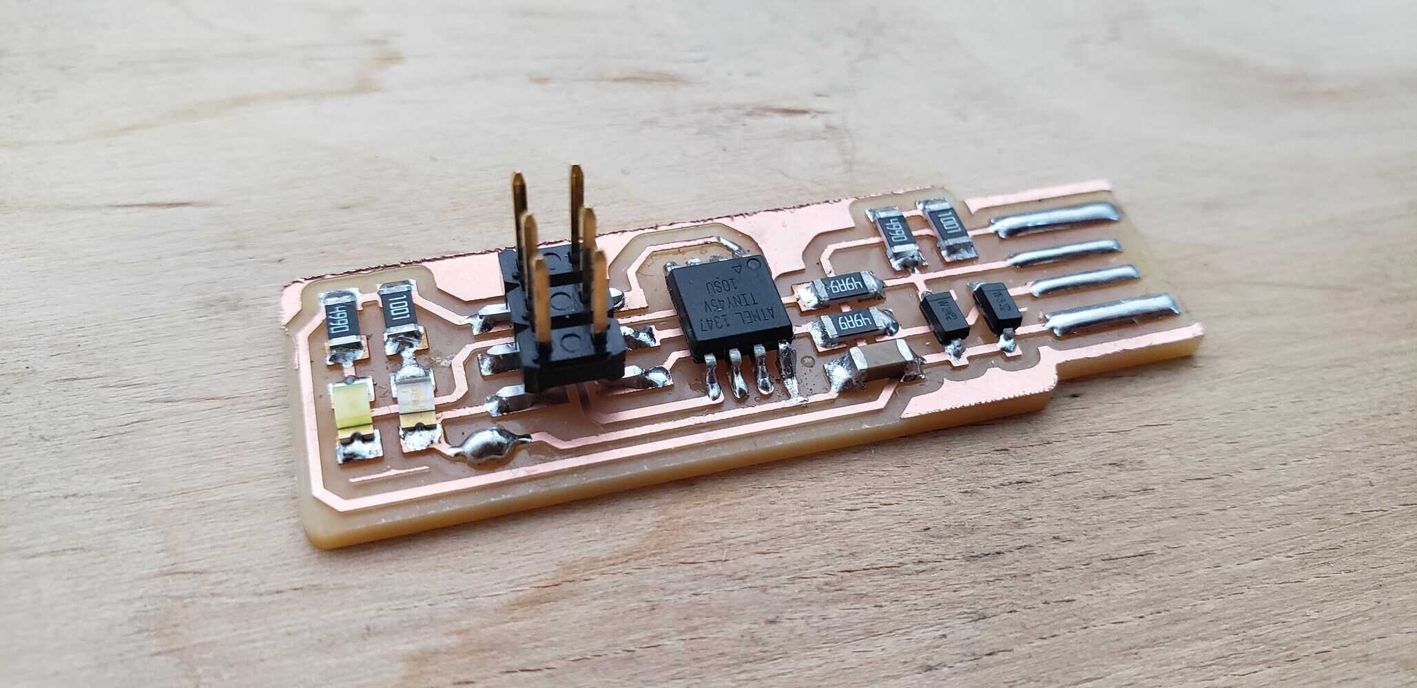 |
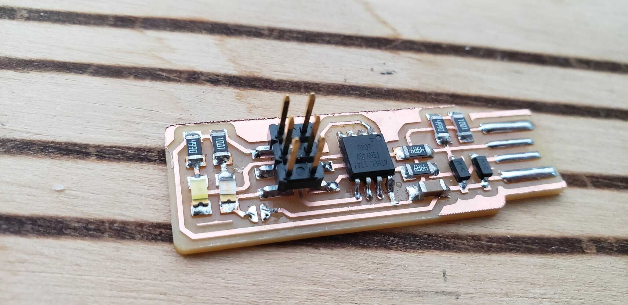 |
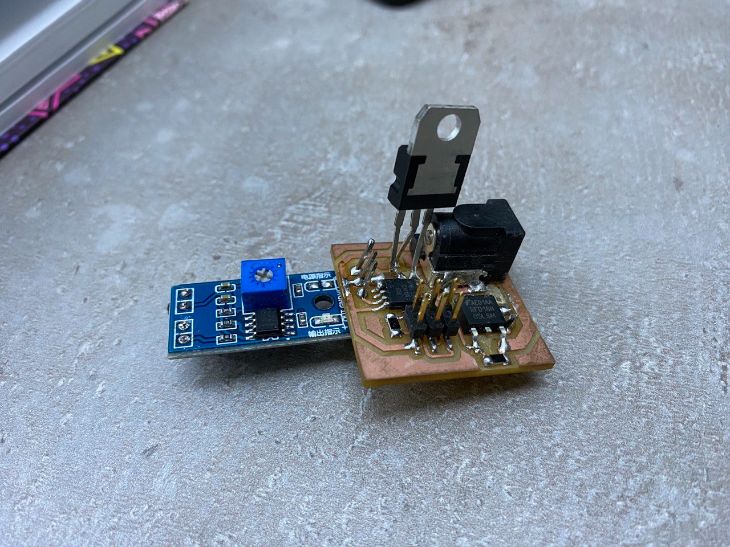
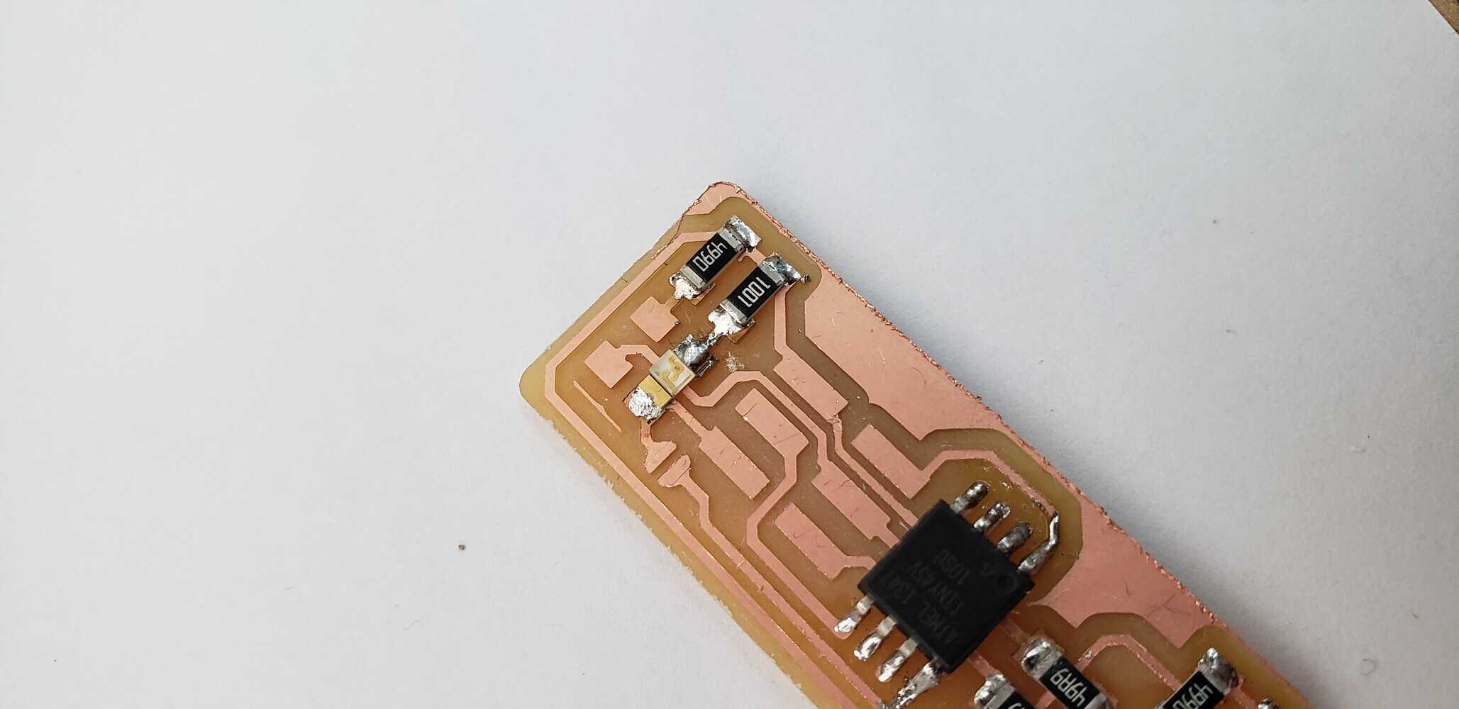
| Finally, my PCB looked like this: |
|---|
 |
7 Programming
This is where we upload the blink program to check whether it works or not.
This part was complicated for me, because I used to program but never with PCBs, and not in a professional way as well. Again I’m going to use Brain’s steps to do it.
7.1 Code
For the code I used one code from my instructor Babken, he allowed me to upload his code:
//
//
// dispenser.45.c
//
// simple software to turn a fogger on/off with delay
//
// Babken Chugaszyan
// 04/05/2020
//
// (c) Babken Chugaszyan 2020
// This work may be reproduced, modified, distributed,
// performed, and displayed for any purpose. Copyright is
// retained and must be preserved. The work is provided
// as is; no warranty is provided, and users accept all
// liability.
//

#include <avr/io.h>
#include <util/delay.h>

#define output(directions,pin) (directions |= pin) // set port direction for output
#define input(directions,pin) (directions &= (~pin)) // set port direction for input
#define set(port,pin) (port |= pin) // set port pin
#define clear(port,pin) (port &= (~pin)) // clear port pin
#define pin_test(pins,pin) (pins & pin) // test for port pin
#define bit_test(byte,bit) (byte & (1 << bit)) // test for bit set
#define Short_delay() _delay_ms(1000) // Short delay (CHANGE DELAY VALUE IN MILISECONDS)
#define Long_delay() _delay_ms(1000) // Long delay (CHANGE DELAY VALUE IN MILISECONDS)

#define input_port PORTB
#define input_direction DDRB
#define input_pin (1 << PB4)
#define input_pins PINB
#define led_port PORTB
#define led_direction DDRB
//#define fog2 (1 << PB2)
#define fog3 (1 << PB3

int main(void) {
    //
    // main
    //

    //
    // set clock divider to /1
    //
    CLKPR = (1 << CLKPCE);
    CLKPR = (0 << CLKPS3) | (0 << CLKPS2) | (0 << CLKPS1) | (0 << CLKPS0);
    //
    // initialize LED pins
    //
    clear(led_port, fog3);
    output(led_direction, fog3);
    //
    // main loop
    //
    while (1) {

  set(led_port,fog3);
  Short_delay();
  clear(led_port,fog3);
  Long_delay();
  }
}
-
For this I used an Ubuntu computer with 2 USB ports.
-
An Avr Programmer.
-
“avrdude” and “avr-gcc” installed
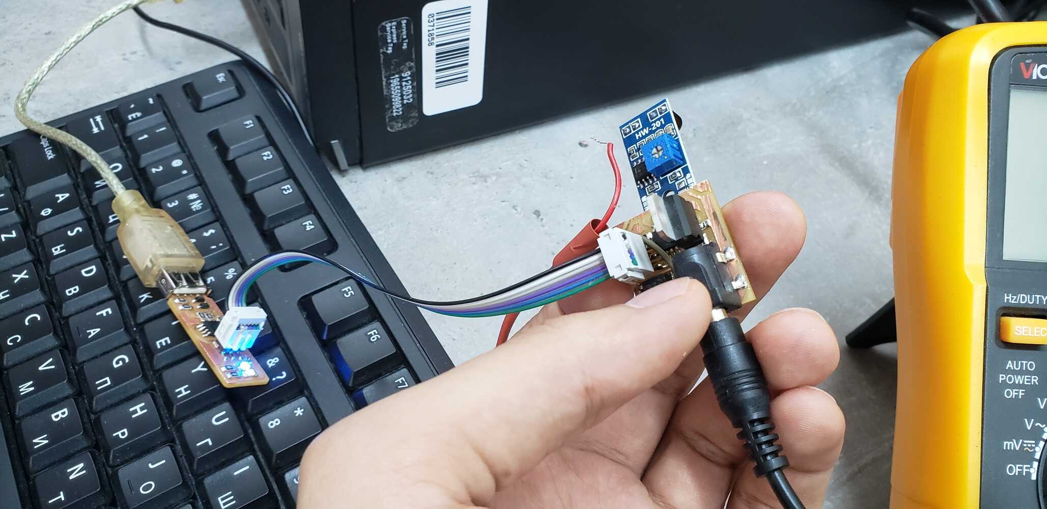
I connected the programmer to the ISP header on my board and where the code was located I opened the terminal.
Then I run the command make flash
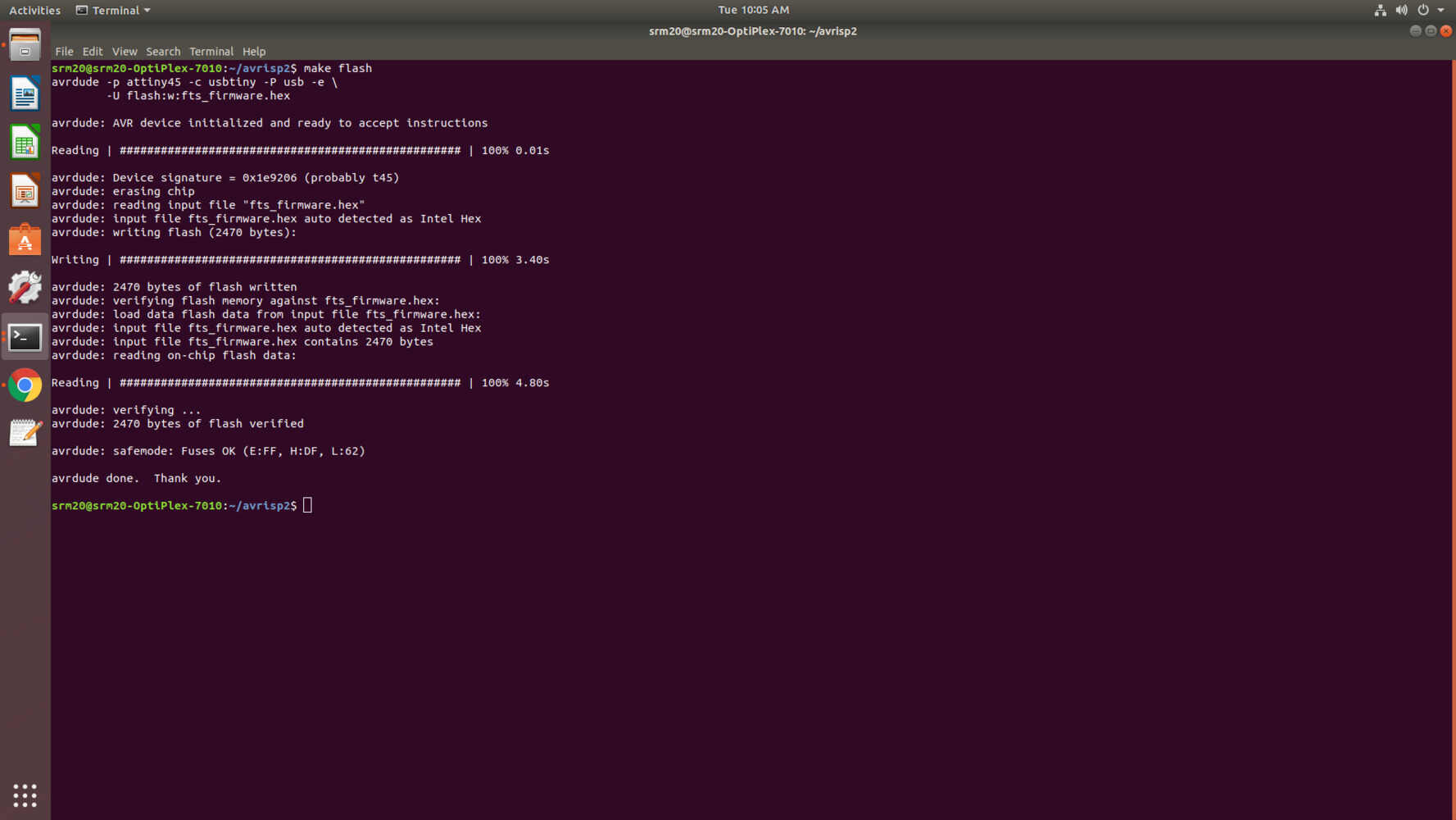
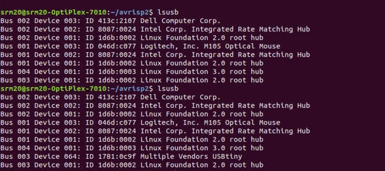
After this I run the command lsusb. If you see a “Multiple Vendors USBtiny” device, it worked!
I don’t know why, I had to make it twice. Maybe it was a connection problem.
7.2 Reset fuse
This information is taken from Brian’s documentation.
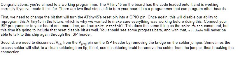
So that’s what I did:
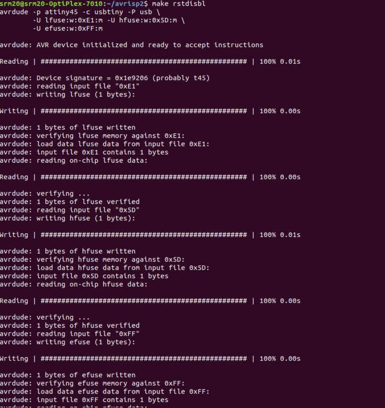
And this is the result:
Important note
We tried to programm another board, and it worked. Here I’m just testing the programmer, wether if it blinks or not. The tarket board was making blink the programmer. We load just a blinking code.