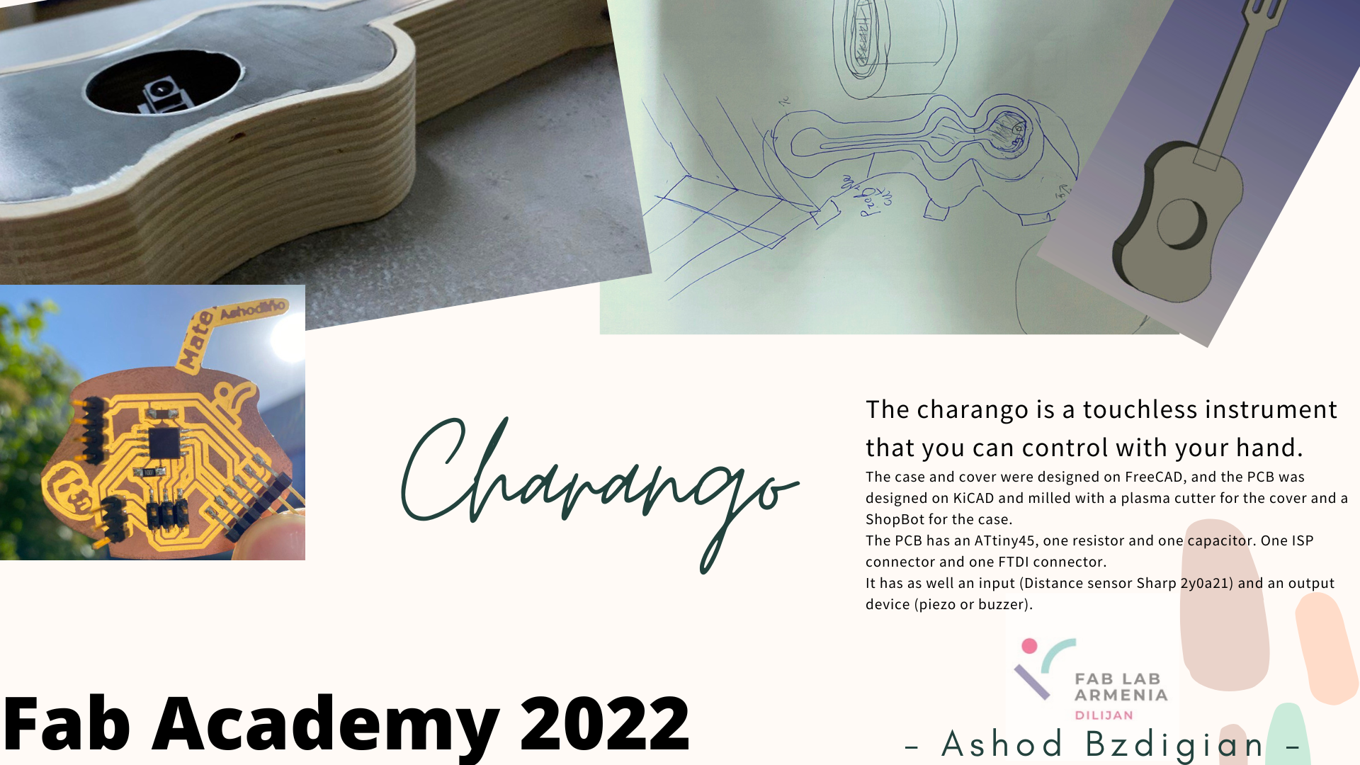
Final Project: How to make an instrument that can be played without touching it
I was discussing with Babken (my instructor), about how we can manage to do the input and output weeks. When we ended up on an idea that we can do a guitar with a buzzer and a distance sensor
License

Esta obra está bajo una Licencia Creative Commons Atribución-NoComercial 4.0 Internacional.
Video and Slide
2D and 3D Modeling
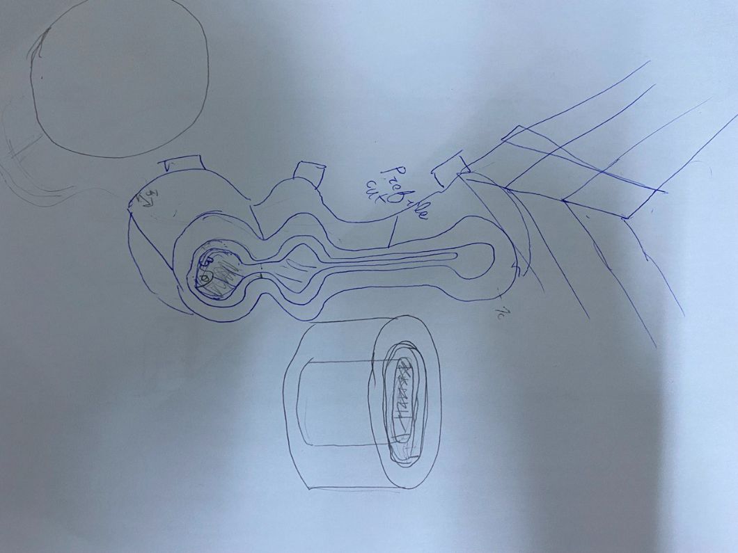
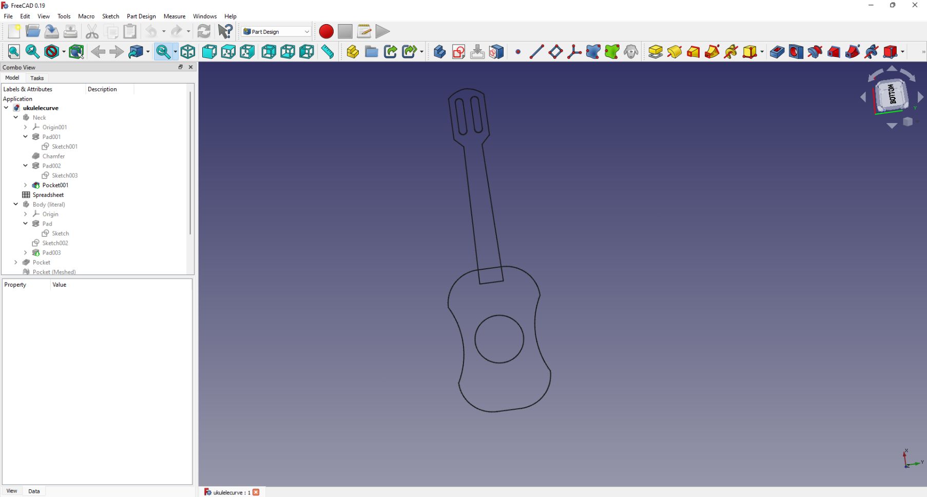
I started with a simple sketch:
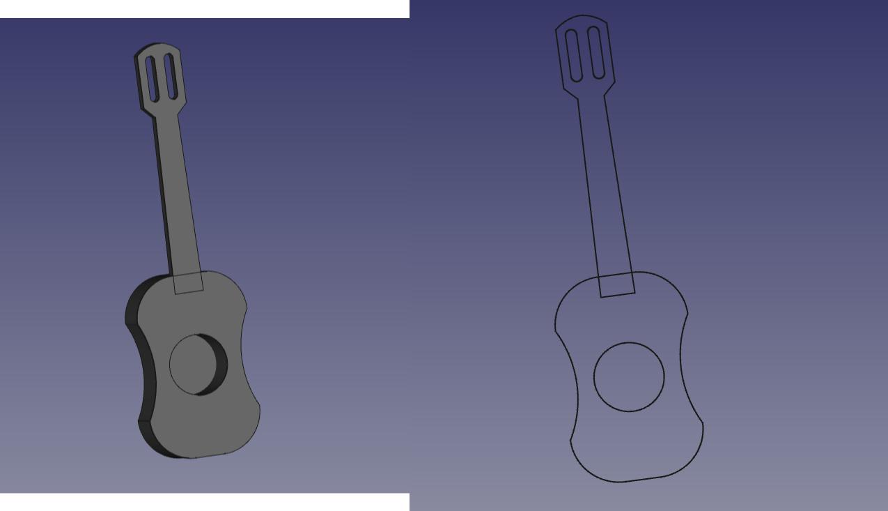
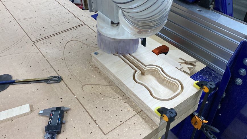
So the cover (the black one), was made with FreeCAD and cut with a plasma cutter.
This goes to the Wildcard Week
 |
|---|
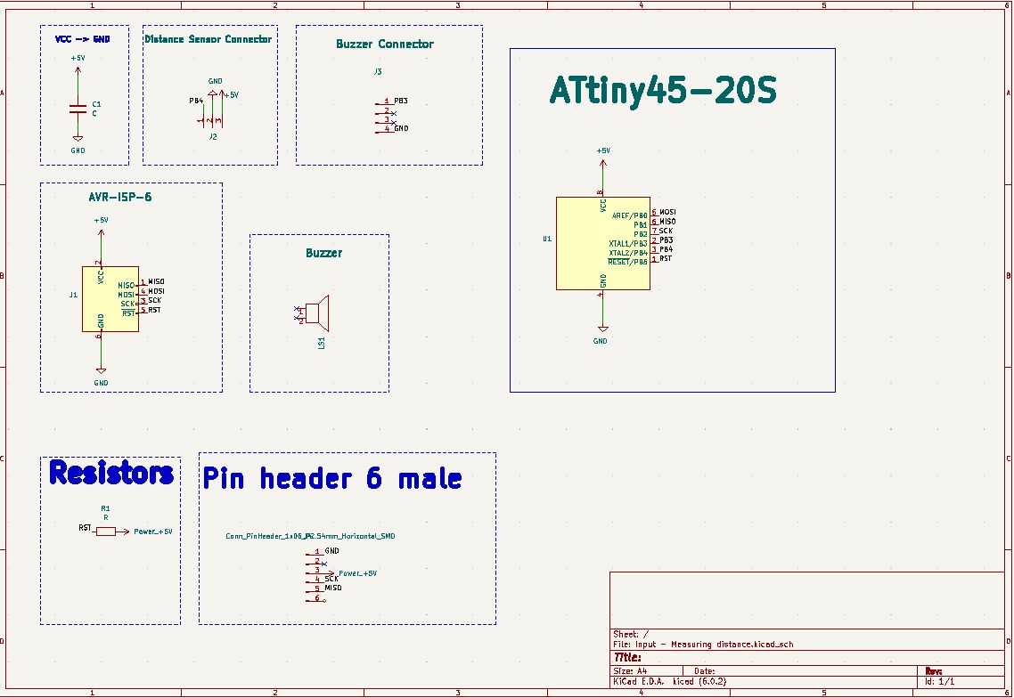
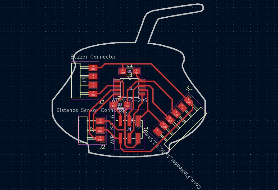
For the PCB I used KiCAD, and I’m very proud about my progress using this software, you can clearly see my progress through the weeks.
By the way, this goes to the Input and Output weeks.
| After it, I milled it: |
|---|
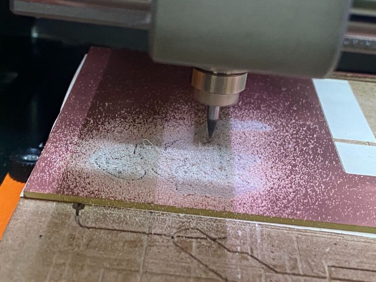 |
| I had a “stupid mistake”. I forgot to put the pad for FTDI cable: |
|---|
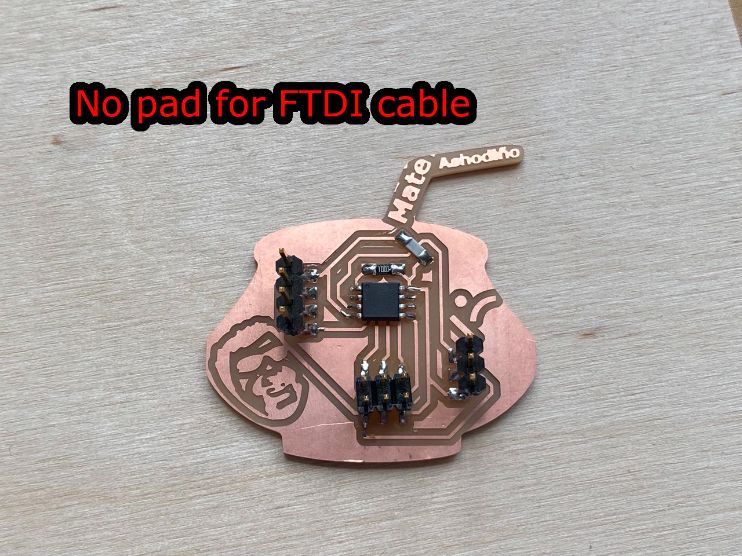 |
| And the PCB has also a good “Easter egg”: |
|---|
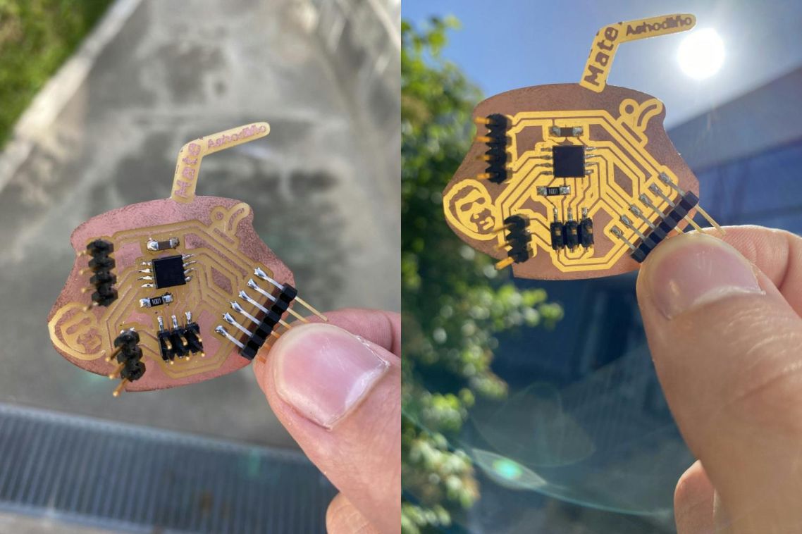 |
| Can you see Babken in the PCB? |
| Then I needed to cut my case for the guitar. |
|---|
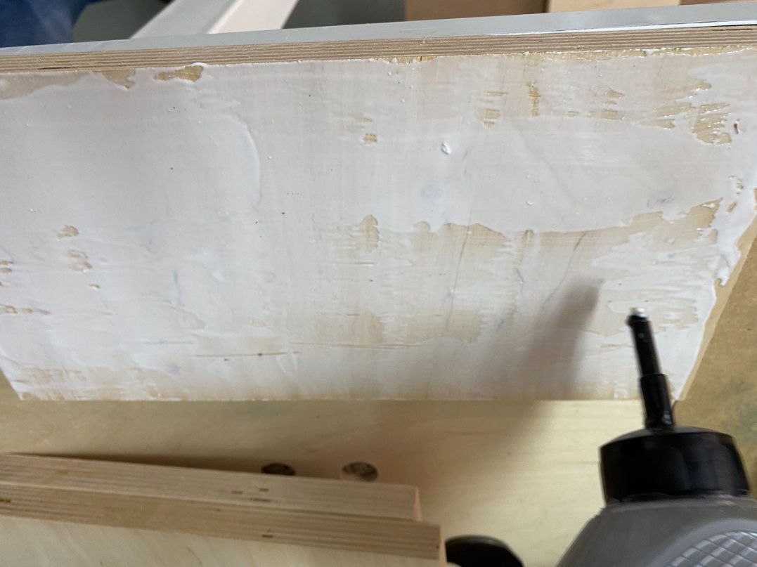
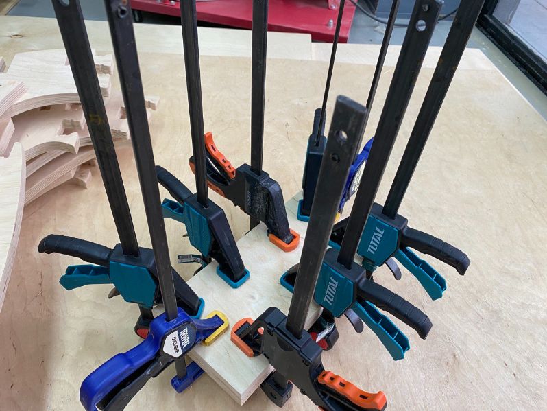
| So, what I did, was to attach two plywoods one with each other with glue and let them dry overnight |
 |
 |
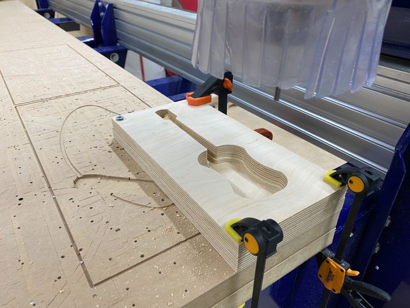
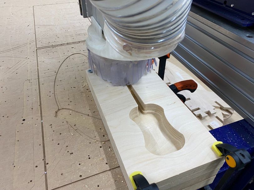
| The next day I started cutting |
|---|
| For this I exported the .svg file to the shopbot software VCarve and put 0.4mm as offset and that’s it |
| After this I cut it |
 |
 |
 |
The cover was made for the Wilcard week but anyway, here are the information and pictures:
| I just need the .svg file for the case. |
|---|
 |
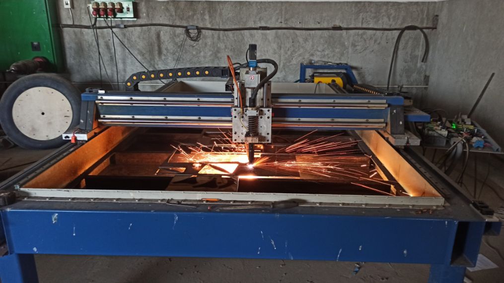
| The Plasma Machine was astonished! I’d never seen something like this |
|---|
 |
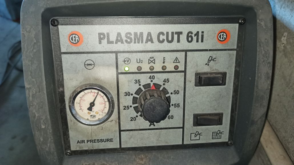
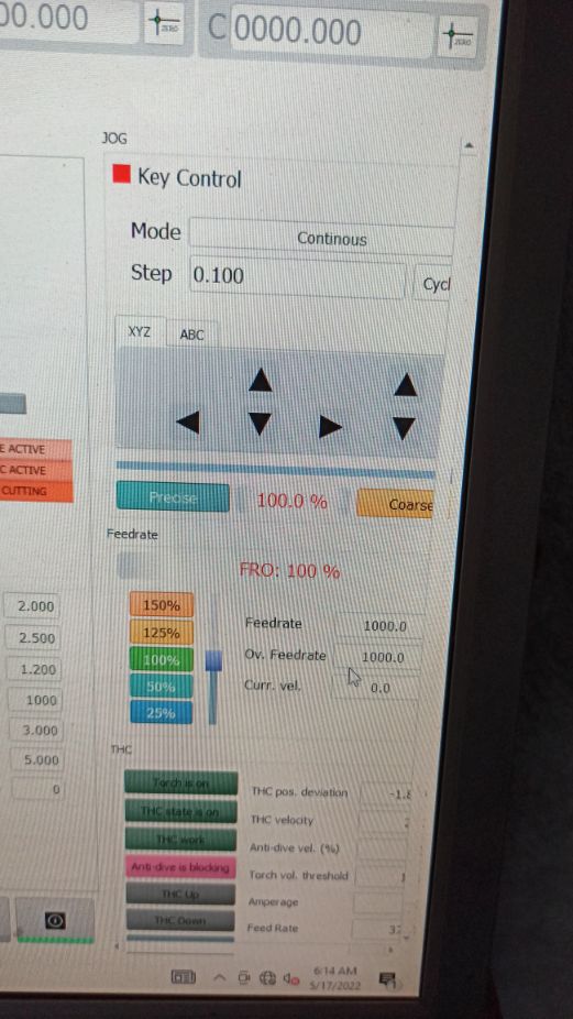
| And this is the “control panel” |
 |
| And here is the “Key Control” in the software |
 |
Software
The software that we used is simCNC from cs-lab.
You can find in this Link
We exported the file as g-code |
|---|
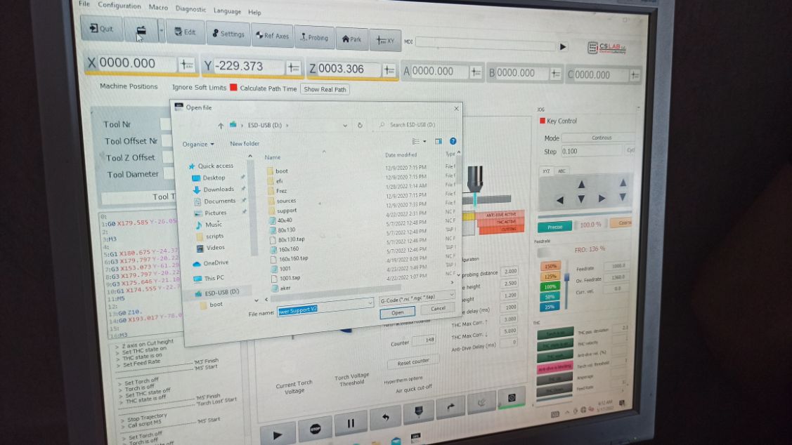 |
We first, cut some test designs to see if the properties on the computer were good:
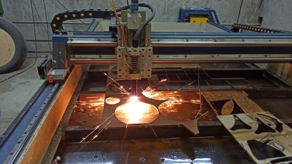 |
|---|
| Here the plasma is cutting the tests |
Note about the test
The tests showed that there is an exisiting problem with the cuts, it’s called “Nozzle wear”, and I will explain it and the solution in the bar of “Problems:”
After the tests, I started cutting my guitar:
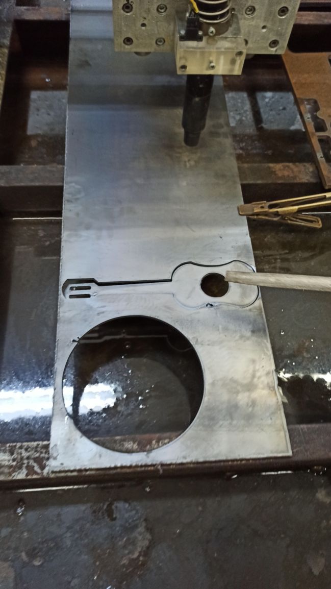 |
|---|
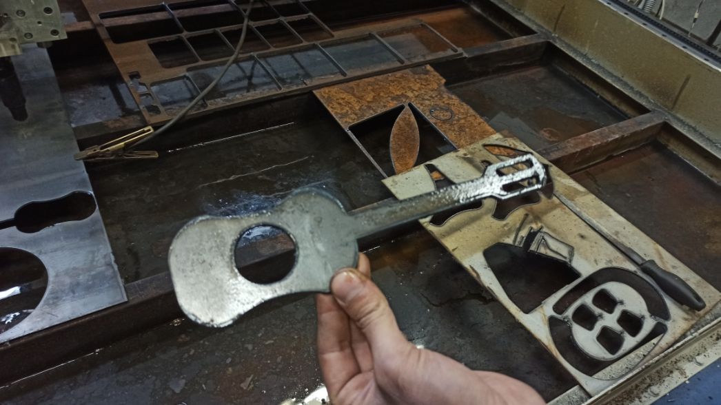 |
The edges were a bit sharp, so I had to sand it:
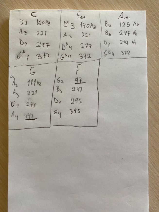
| I needed to test the frequency of the tunes |
|---|
| For this, I looked in internet some chords |
 |
| And I start testing with a Digital Oscilloscope |
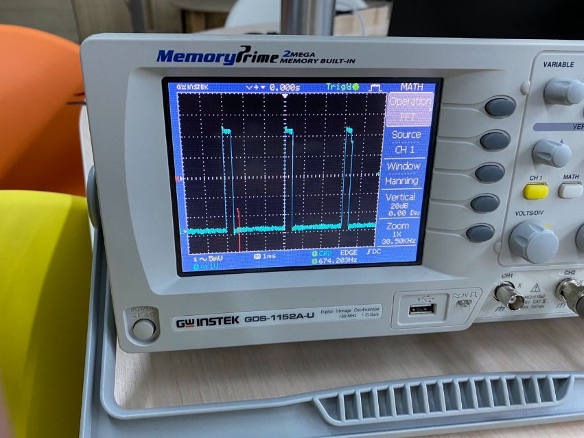 |
 |
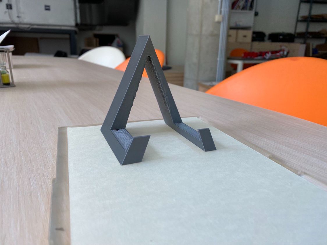
| I added as an additive a stand for the guitar. |
|---|
| For this I went to FreeCAD and I started with the design. |
| First I create a simple triangle: |
|---|
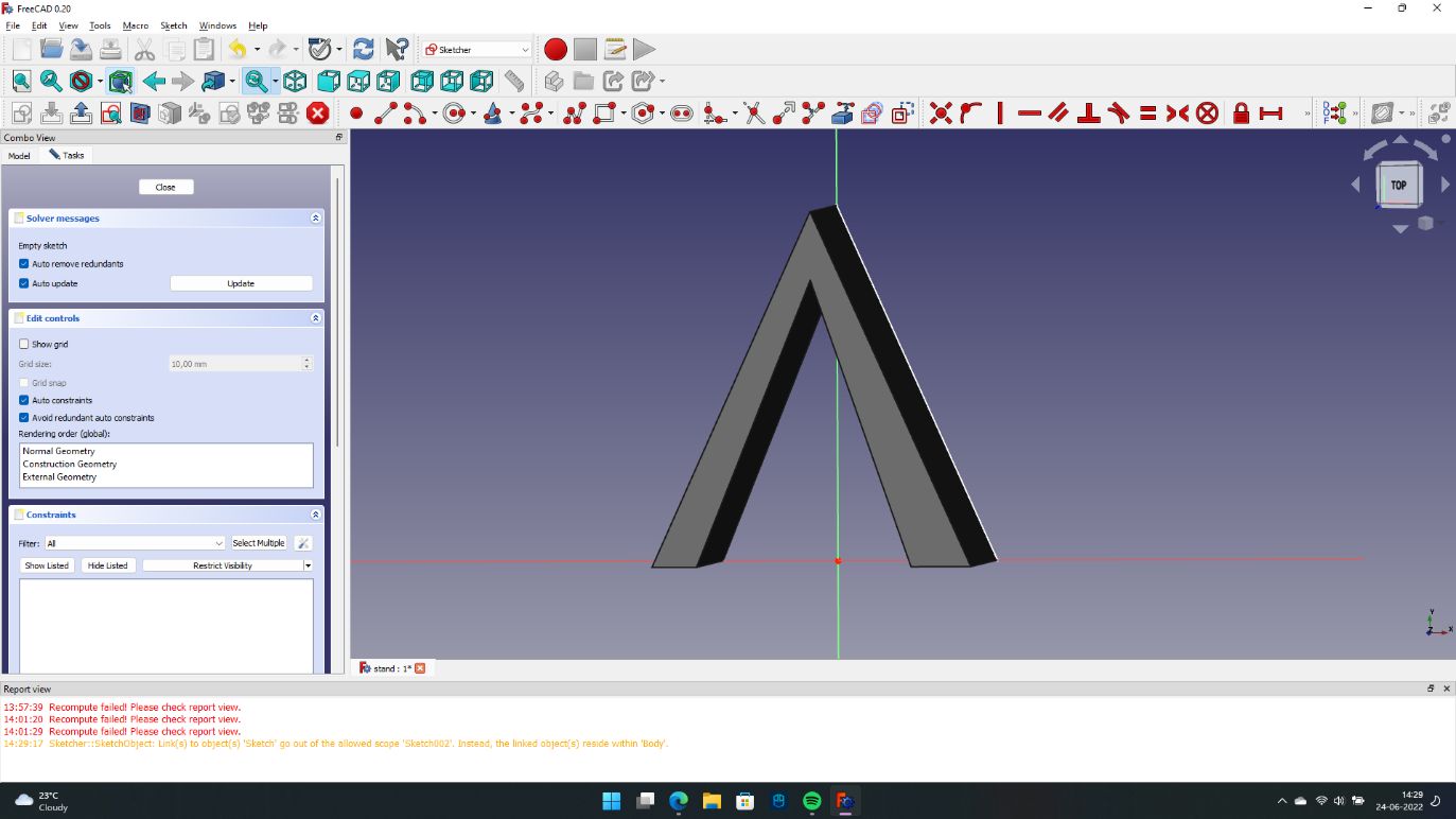 |
| Then, I added the legs |
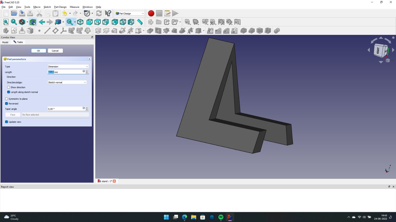 |
| After this, I used the feature pocket to create the “teeth” of the stand which will help the guitar to maintain its posture |
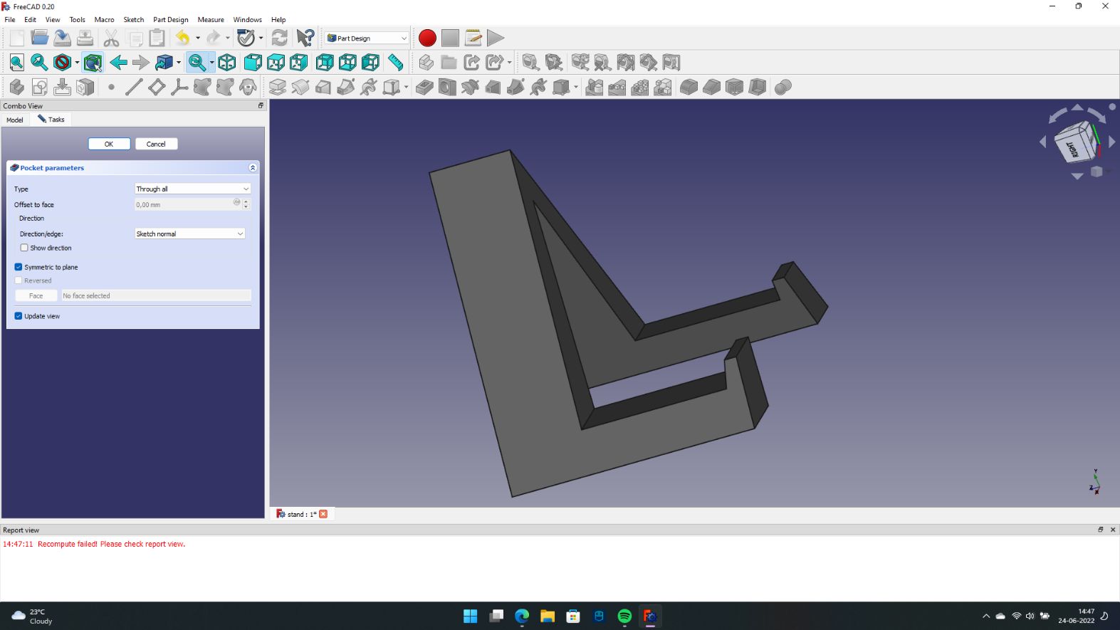 |
| After this I started with the printing process |
|---|
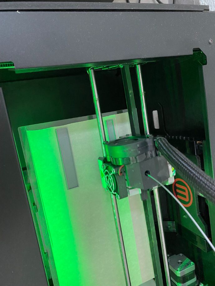 |
| The stand looks pretty cool |
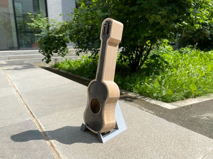
 |
| And this is how it looks with the guitar |
 |
Materials (BOM)
| Qty | Description | Price | Link |
|---|---|---|---|
| 1 | Distance sensor | 17.00 $ | link |
| 1 | Attiny45 | 1.47 $ | link |
| 1 | Resistor SMD 1KOHM | 0.02 $ | link |
| 1 | Capacitor | 0.13 $ | link |
| 1 | Piezo | 0.57 $ | link |
| 1 | Metal | 10.00 $ | Not Available |
| 2 | Plywood 150mmx100mm | 22.00 $ | Not Available |
| Total | 51.19 $ |
Programming:
For programming I used the OS Linux, where is a very solid OS for programming.
I tried to program on my laptop that has Windows, but was impossible for me.
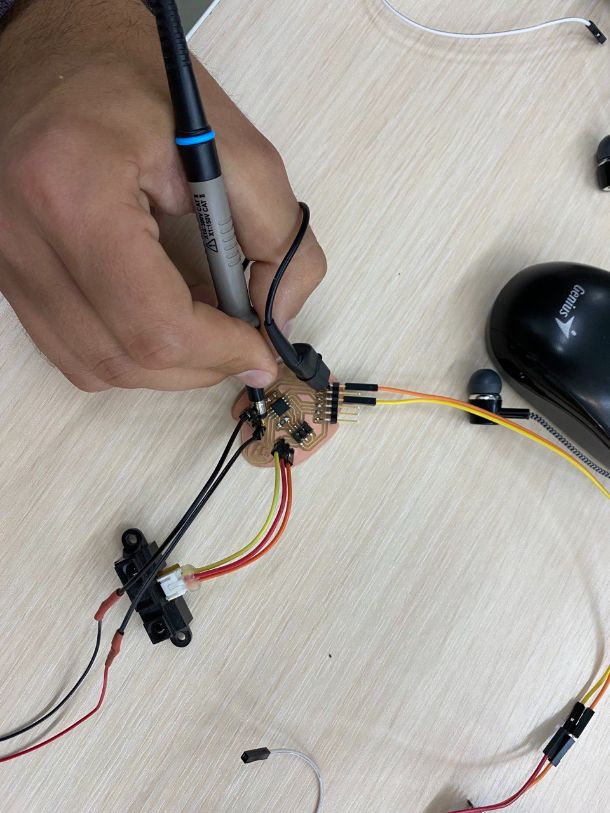
| I also used my old trustfull Programmer that I made on the Electronic design week for programming it. |
|---|
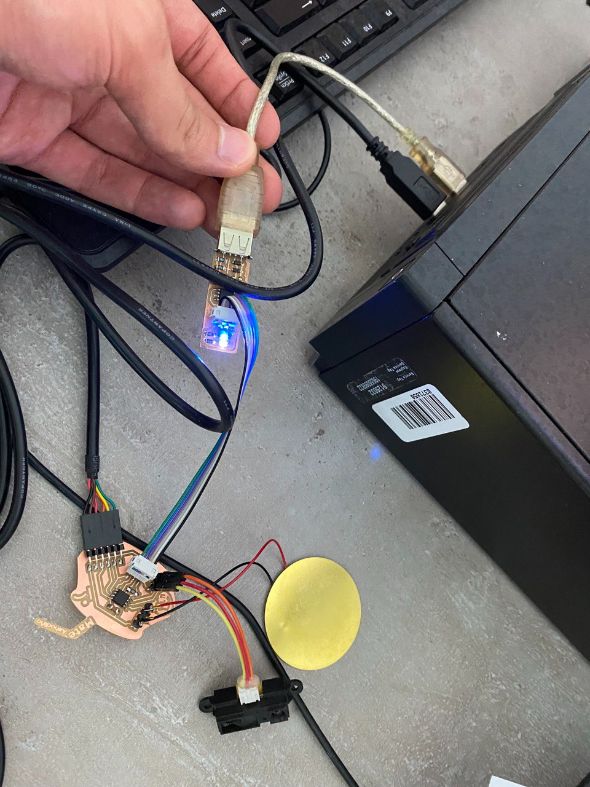 |
| Here you can see the piezzo (output-device) with the distance sensor (input-device) |
Getting different Frequencies:
So for this part, I used a beautiful chord path:
I took this frequencies from the following website
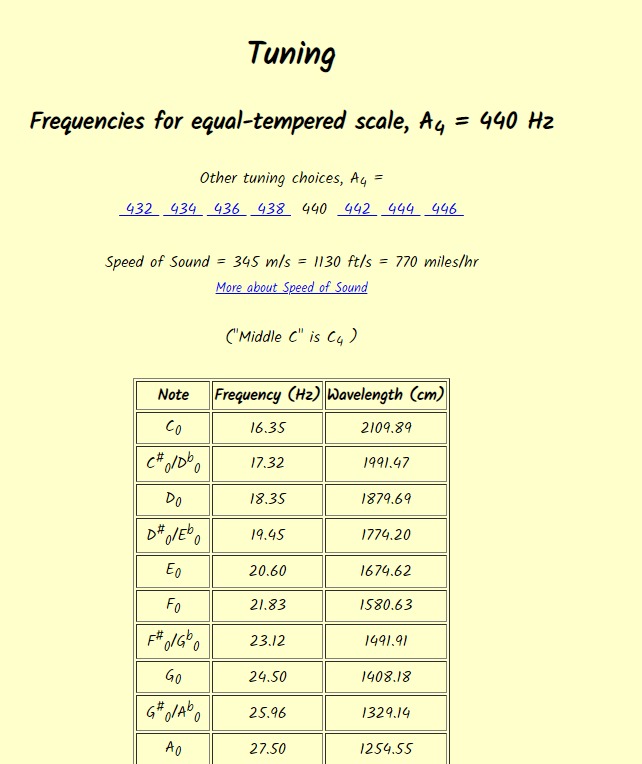
(Source: mtdu.edu)
Once that I had the frequencies that I wanted I installed an app for android called Music Note Identifier
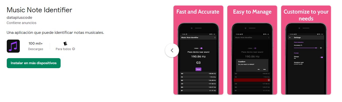
And I started to look for the appropiate frequency:
This is the following code:
Code:
Important Note
The code that appears here is the same code for the “Input week” because both weeks are inside of my final project.
Note about the code
Inside of the code you will find the double-bars “//” that will explain the code
//
//
// Theremin
//
// simple software to measure distance and make sound delays
//
// (c) Babken Chugaszyan, Ruslan Gindullin, Ashod Bzdigian 2022
// This work may be reproduced, modified, distributed,
// performed, and displayed for any purpose. Copyright is
// retained and must be preserved. The work is provided
// as is; no warranty is provided, and users accept all
// liability.
//

#include <avr/io.h>
#include <util/delay.h>

#define output(directions,pin) (directions |= pin) // set port direction for output
#define input(directions,pin) (directions &= (~pin)) // set port direction for input
#define set(port,pin) (port |= pin) // set port pin
#define clear(port,pin) (port &= (~pin)) // clear port pin
#define pin_test(pins,pin) (pins & pin) // test for port pin
#define bit_test(byte,bit) (byte & (1 << bit)) // test for bit set
#define Short_delay() _delay_ms(1) // Short delay (CHANGE DELAY VALUE IN MILISECONDS)
#define Long_delay() _delay_ms(1) // Long delay (CHANGE DELAY VALUE IN MILISECONDS)

#define led_port PORTB
#define led_direction DDRB
#define buz (1 << PB3)

short int re;//reading variable

void initADC()
{
  ADMUX =
            (0 << ADLAR) |     // left shift result
            (0 << REFS1) |     // Sets ref. voltage to VCC, bit 1
            (0 << REFS0) |     // Sets ref. voltage to VCC, bit 0
            (0 << MUX3)  |     // use ADC2 for input (PB4), MUX bit 3
            (0 << MUX2)  |
            (1 << MUX1)  |
            (0 << MUX0);

  ADCSRA =
            (1 << ADEN)  |     // Enable ADC
            (1 << ADPS2) |     // set prescaler to 64, bit 2
            (1 << ADPS1) |     // set prescaler to 64, bit 1
            (0 << ADPS0);      // set prescaler to 64, bit 0
}

void delay2micros(short int i){   // Delay microseconds
      while (i != 0) {
      _delay_us(2);
      --i;
      }
}
int valuecleaner(){  // Averaging input to eliminate analog noise
short int i = 0;
int val = 0;
for(i = 0; i < 10; ++i){    // reading 10 times
  initADC();
      ADCSRA |= (1 << ADSC);         // start ADC measurement
      while (ADCSRA & (1 << ADSC) ); // wait till conversion complete
    val += ADCW;
    }
    val /=10;  // dividing by 10
    return val;
    }

int main(void) {

   //
   // main
   //

   //
   // set clock divider to /1
   //
   CLKPR = (1 << CLKPCE);
   CLKPR = (0 << CLKPS3) | (0 << CLKPS2) | (0 << CLKPS1) | (0 << CLKPS0);
   //
   // initialize LED pins
   //
   clear(led_port, buz);
   output(led_direction, buz);
   //
   // main loop
   //
   while (1) {

    if(valuecleaner() < 65) re = 0;  // Capping low values to eliminate noise
    else re = valuecleaner();


      set(led_port,buz);
      delay2micros(5000/re);     // Dividing a constant by variable to linearize the scale and delaying for the result amount of microseconds

      clear(led_port,buz);
      delay2micros(5000/re);  // Dividing a constant by variable to linearize the scale

   }
}
Note about the Frequency
If you want to change the frequency you need to change the values of this part of the code:
set(led_port,buz);
delay2micros(5000/re);     // Dividing a constant by variable to linearize the scale and delaying for the result amount of microseconds

clear(led_port,buz);
delay2micros(5000/re);  // Dividing a constant by variable to linearize the scale
Note about the instrument
The process of changing the tone (frequency) is still rusty and maybe a bit tedious to do. Because first you need to change the value, and then look into the app for the correct pitch.
I’m planning to find a better way in the future.