9. Molding and casting
Group Assignment Page
For the Group Assignment Page we had to read the safety datasheet of the material that we were going to use.
This is taken from the Safety Data Sheet of Smooth-On
The Material Safety Data Sheet (MSDS) for this or any Smooth-On product should be read prior to use and is available upon request from Smooth-On. All Smooth-On products are safe to use if directions are read and followed carefully.Be carefulUse only with adequate ventilation. Contact with skin and eyes may cause irritation. Flush eyes with soap and water for 15 minutes and seek immediate medical attention. Remove from skin with waterless hand cleaner followed by soap and water.
IMPORTANT - The information contained in this bulletin is considered accurate. However, no warranty is expressed or implied regarding the accuracy of the data, the results to be obtained from the use thereof, or that any such use will not infringe upon a patent. User shall determine the suitability of the product for the intended application and assume all risk and liability whatsoever in connection therewith.
As well, we saw the different moulding types and application for every mould and cast.
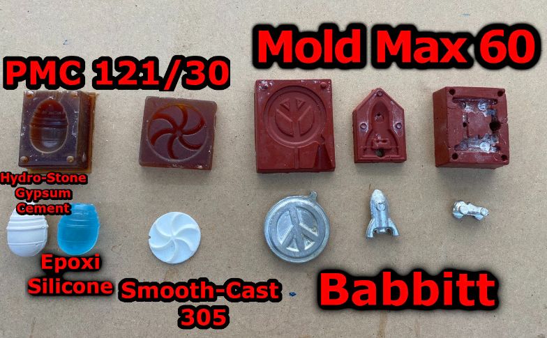
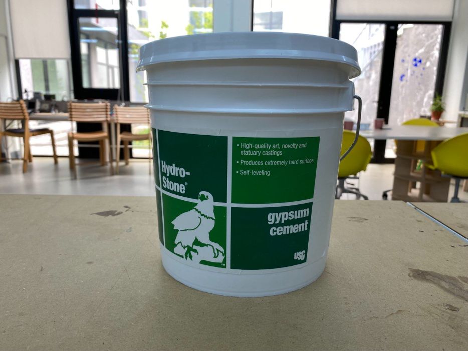
My favourite was the Hydro-Stone® Gypsum Cement that is especially suitable where high strength and resistance to water absorption are necessary. It is ideal for applications in both the tooling & prototyping and art & statuary categories.
Research
As this is a new week, I need to have some knowledge about what am I going to do.
For this reason I search for some information on Internet.
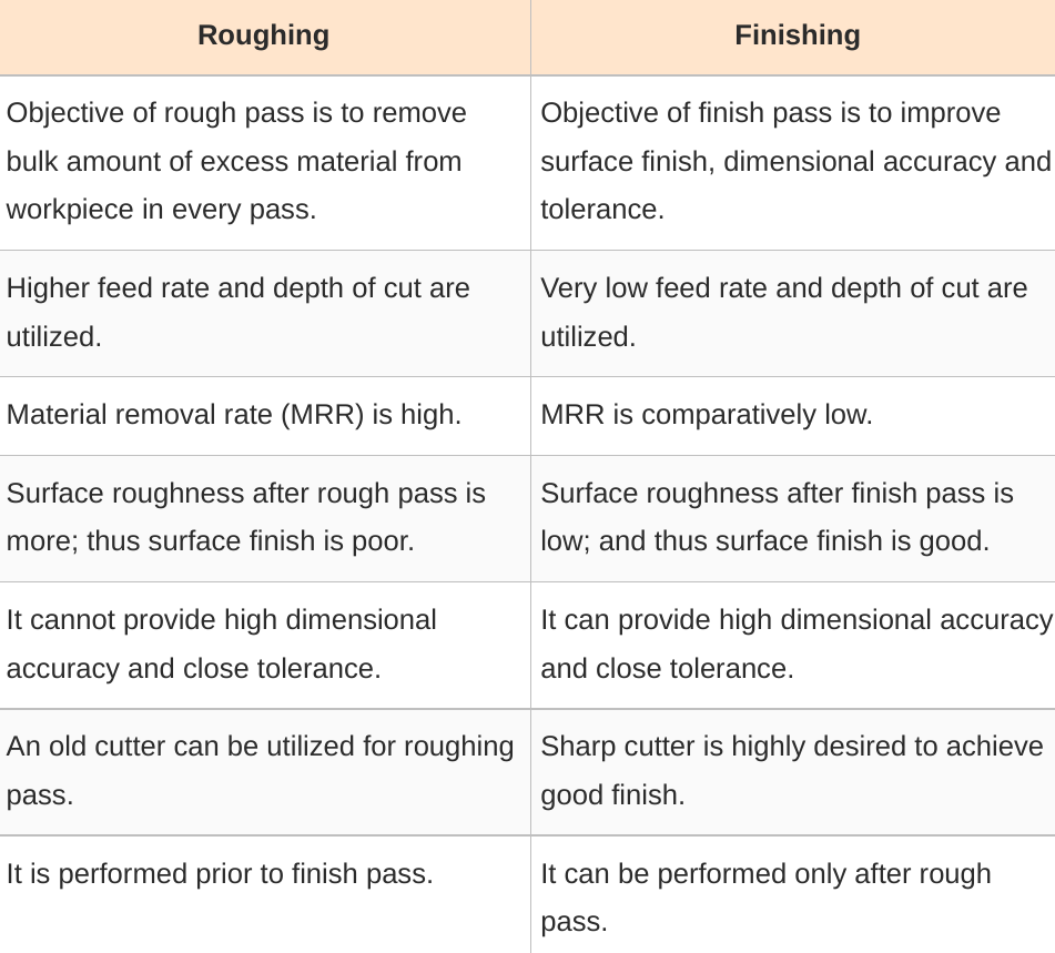
Difference Between Roughing and Finishing in Machining
One thing that we must know before cutting in 3 axes, is that there is a concept called Roughing and Finishing cuts.
The information from this website is very good and it has a table with these differences.
There is a video that explains better this process
Rules for using the Roland Smr-20
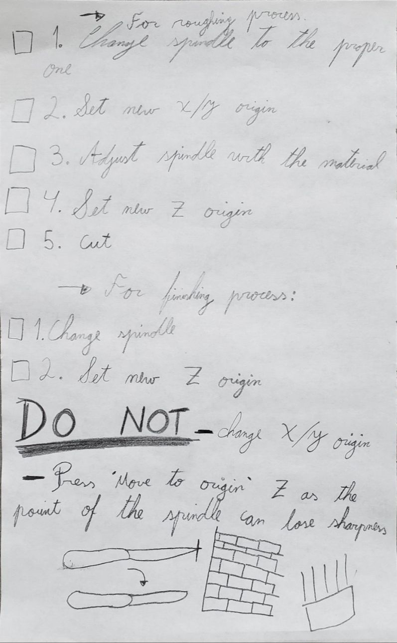
This is a simple check-list that I did in order to not have mistakes using the Roland
Insert Molding
In Fab Lab Dilijan is possible to do insert and overmolding
This video explains design tips, tricks and techniques to optimize your part using insert molding.
It basiically responds to the following concepts:
- What is Insert Molding?
- Benefits of Insert Molding
- Guidelines for Standard Inserts
- Guidelines for Custom Inserts
- Material Considerations
- File Preparation
Terminology
It is very useful to learn the terminology of what we are going to work with:
Sprue: Is the vertical passage through which liquid material is introduced into a mold.
Pouring_cup: The pouring cup collects the liquid metal for pouring and facilitates the flow of the metal into the mold. 
Runner/Gate: Branches of channels or halls and doors connected to the sprue to distribute material. 

Assignment
FreeCAD
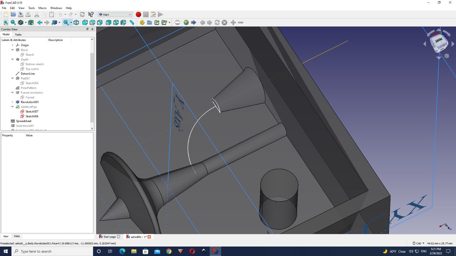
It was a bit difficult to design my mould, I some complications with it.
This is the parameters that I used to design this:
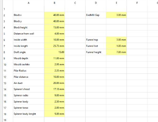
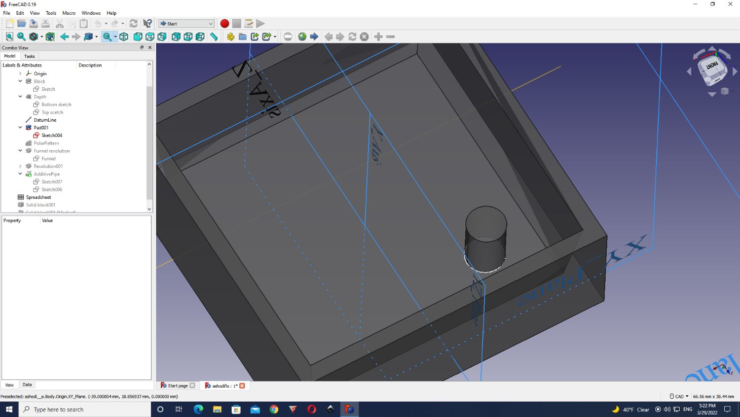
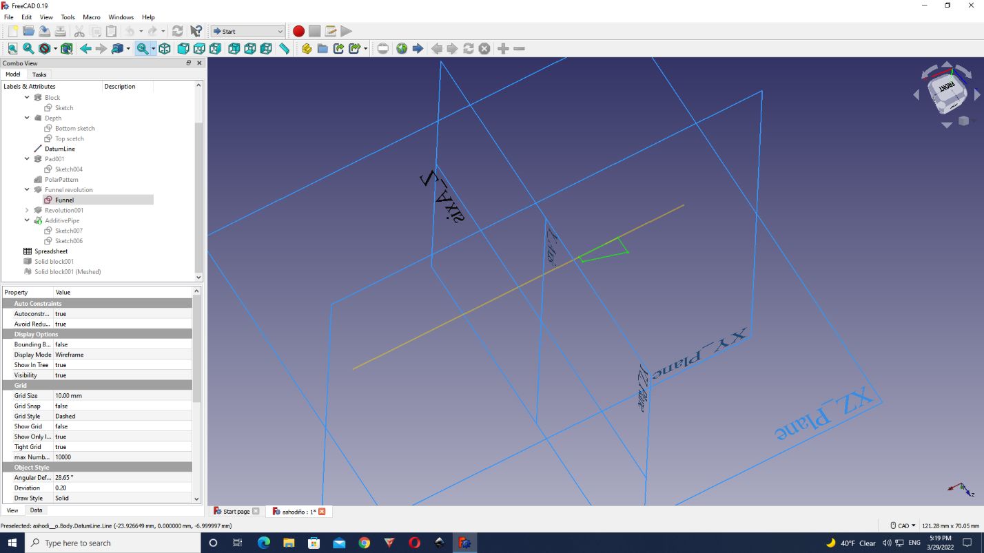
I learnt that there is a method to work in another place than the origin (0,0,0) using the tool “DatumLine”.
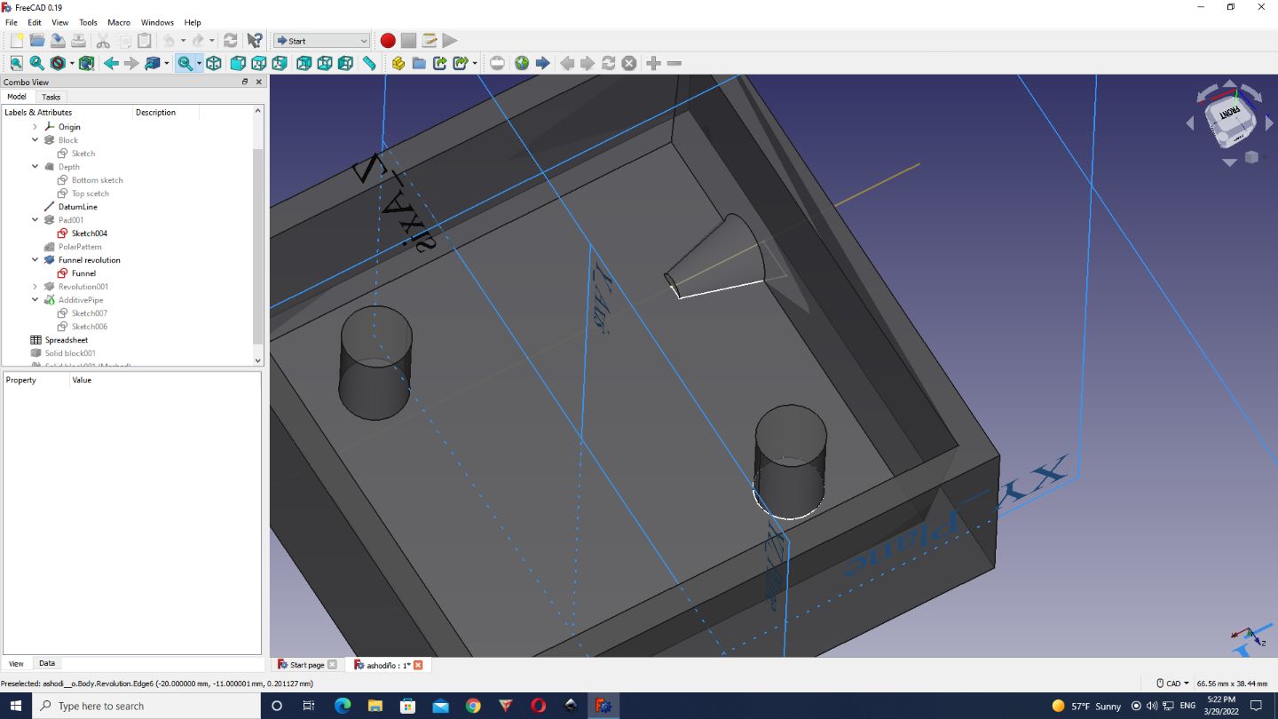
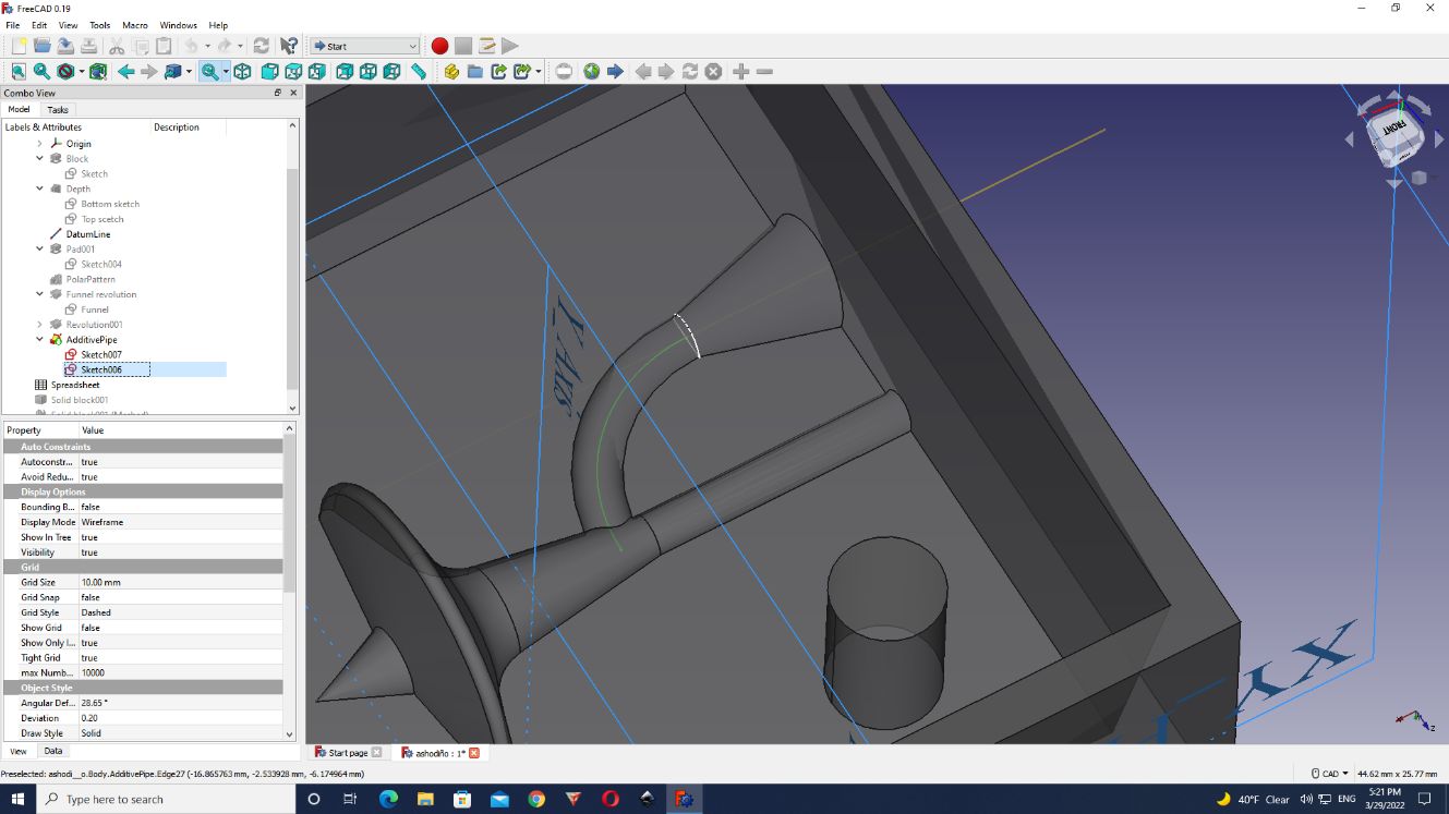
For creating the channel of the funnel we put some parameters as the ‘Funnel height’ to create this curve. And then selecting the both, the funnel and the curve, I clicked on AdditivePipeline.
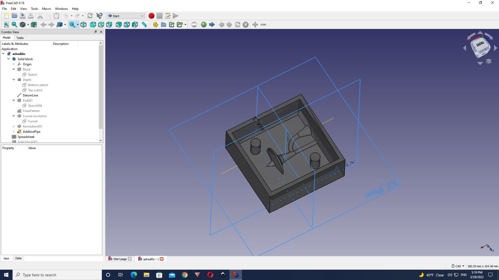
After the design on FreeCAD was ready, I created a mesh file, and then exported it as .stl fike.
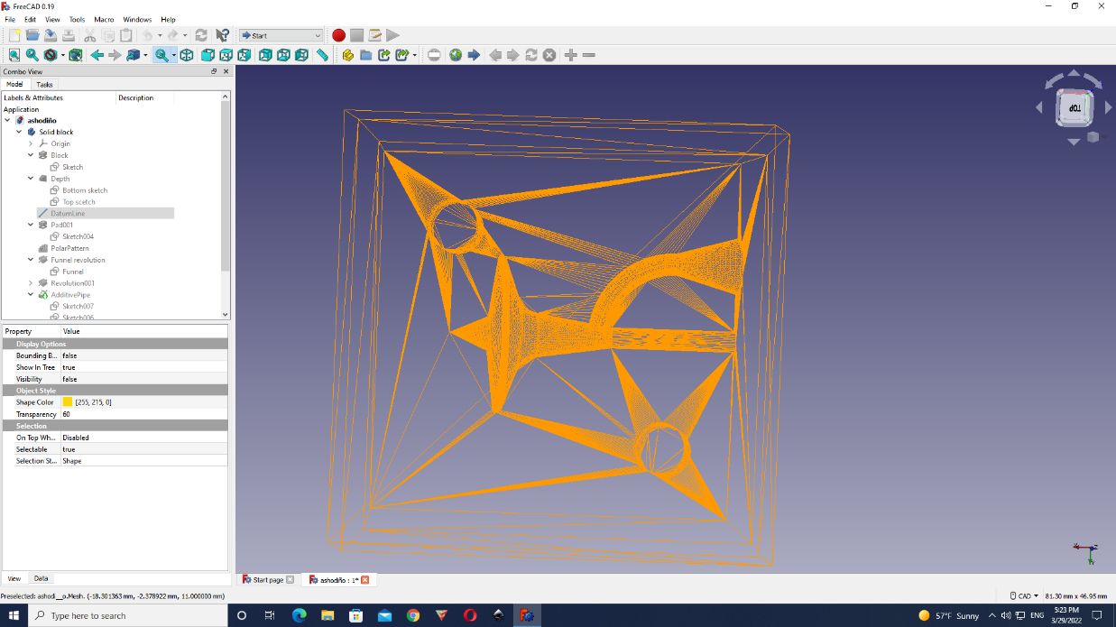
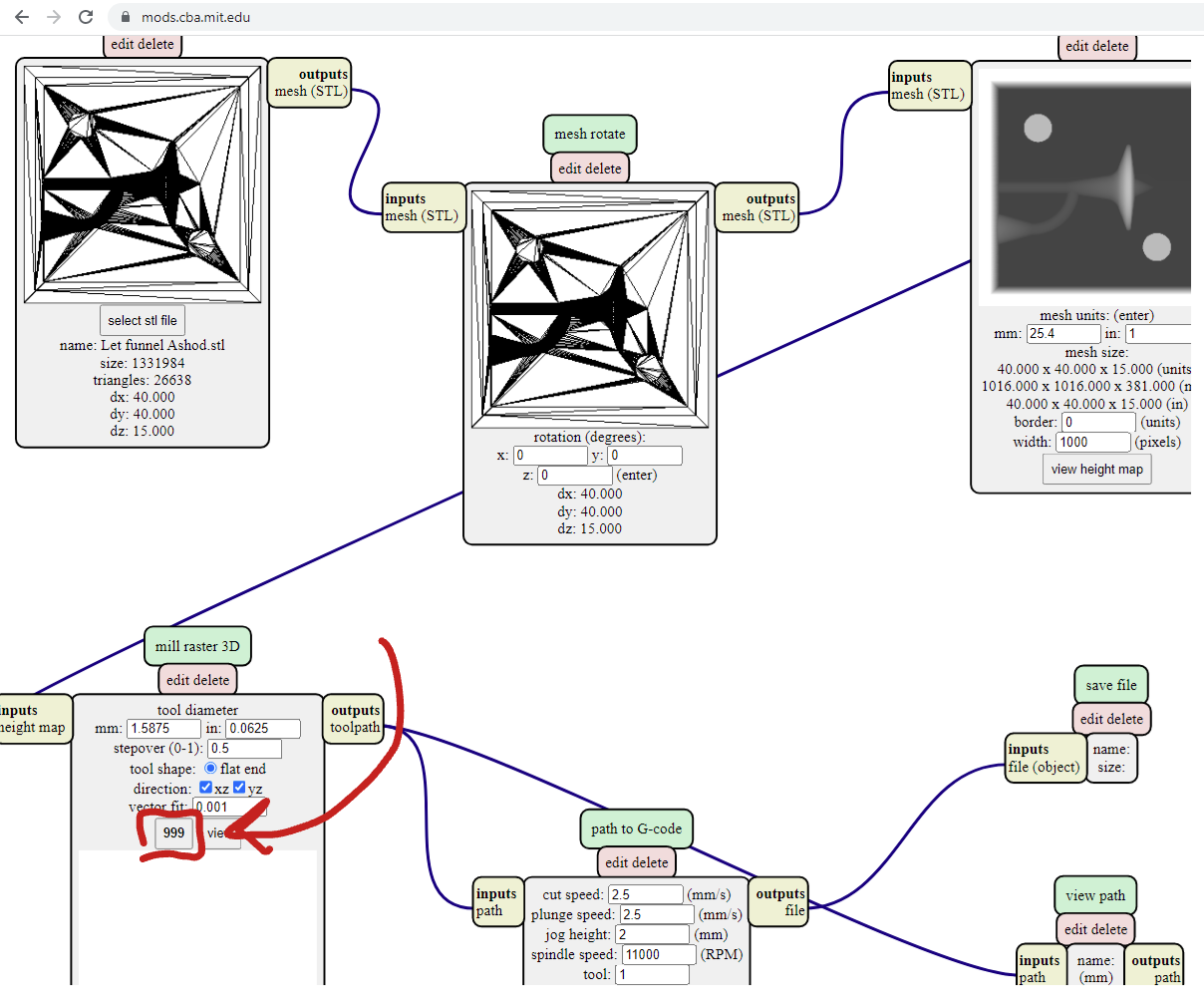
FABMods
We tried to use FabMods, but it was impossible because everytime we tried to upload files, the numbers that goes down (999, 998, 998…etc) didn’t go down and they stayed at 999. After a while it says ‘out of memory’ so we finally used VCarve
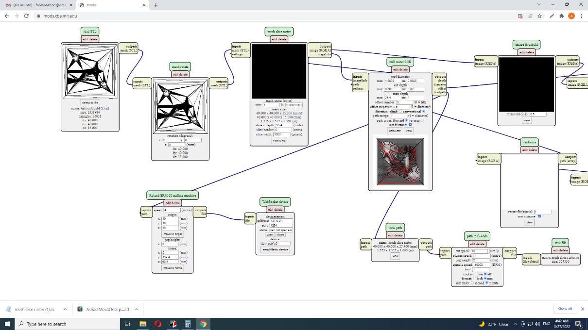

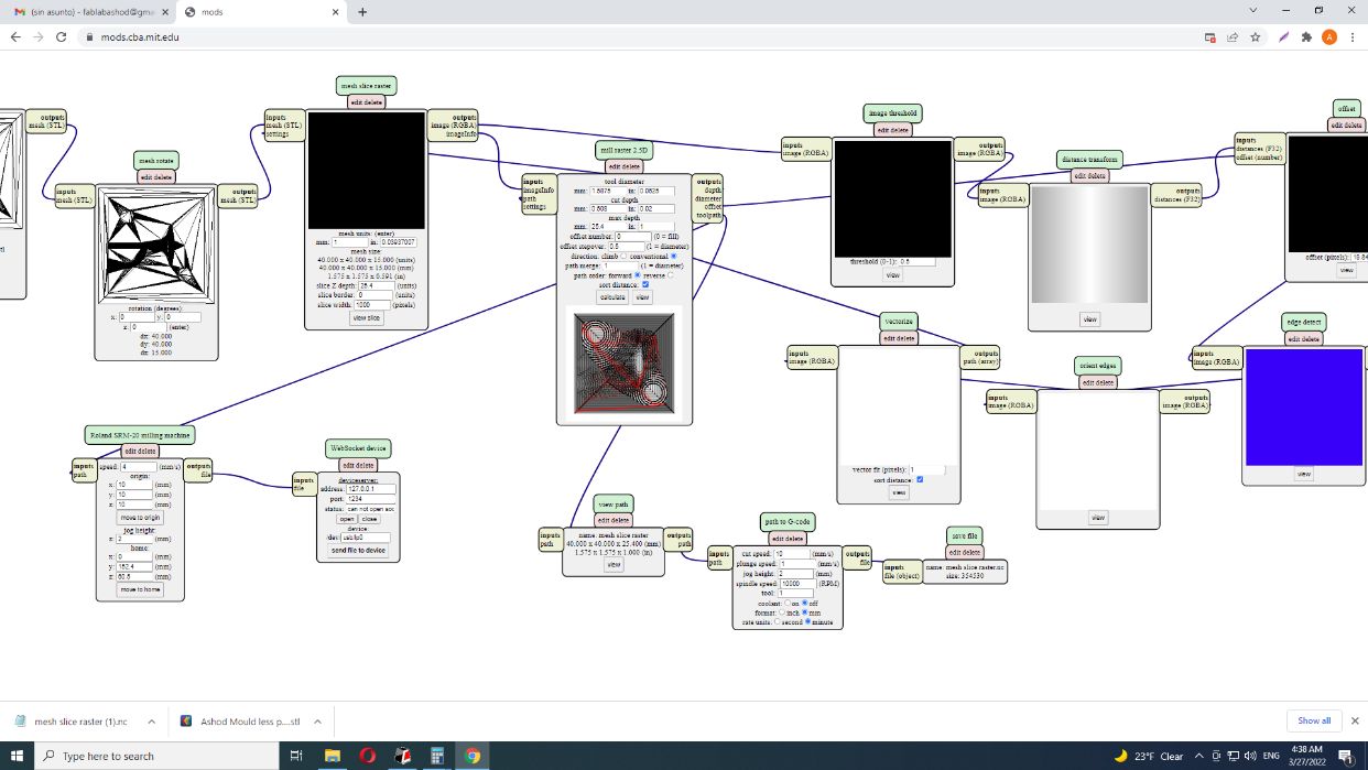
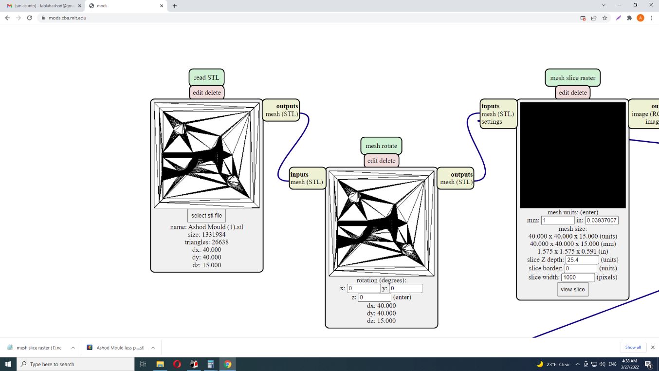
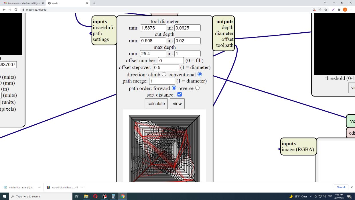
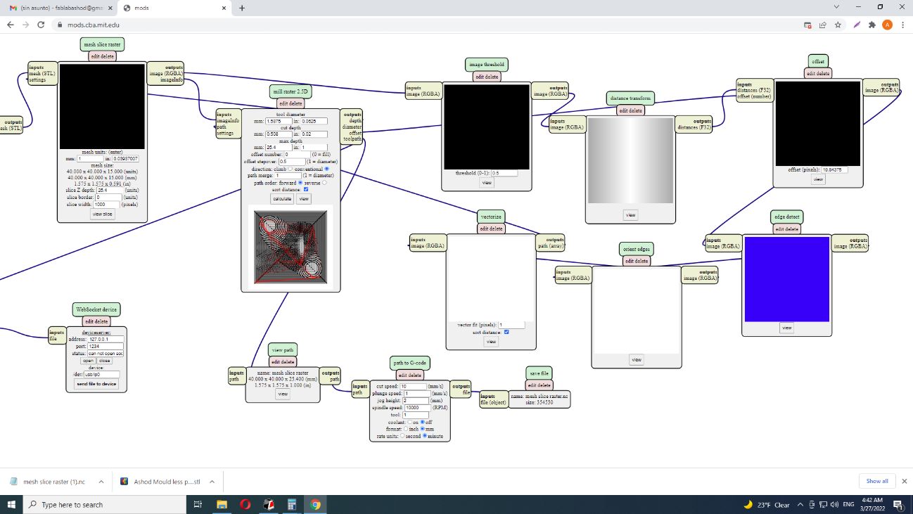
As you can see it stays in 999 and it doesn’t go down.

VCarve
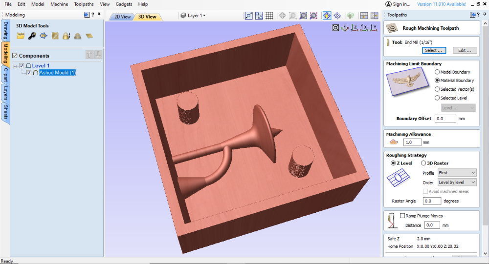
After using FreeCAD software I put my file into VCarve and started to do the traces of 2.5D and 3D:
This is 2.5D traces.
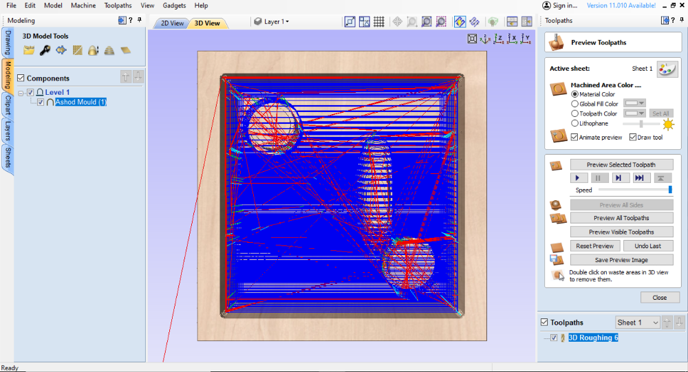
This is 3D traces
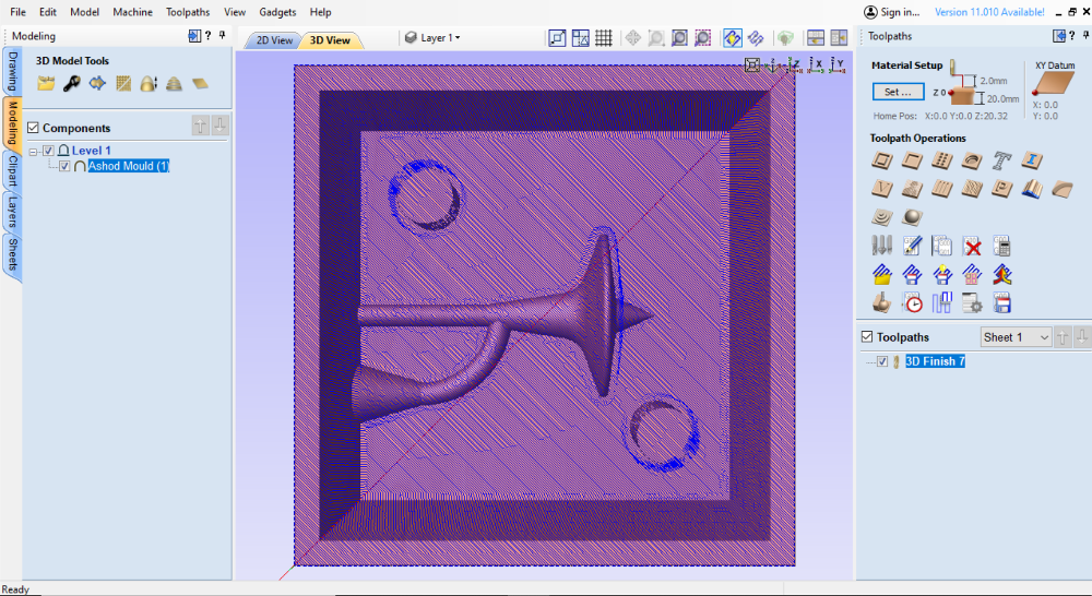
Then, I exported the files as .rol
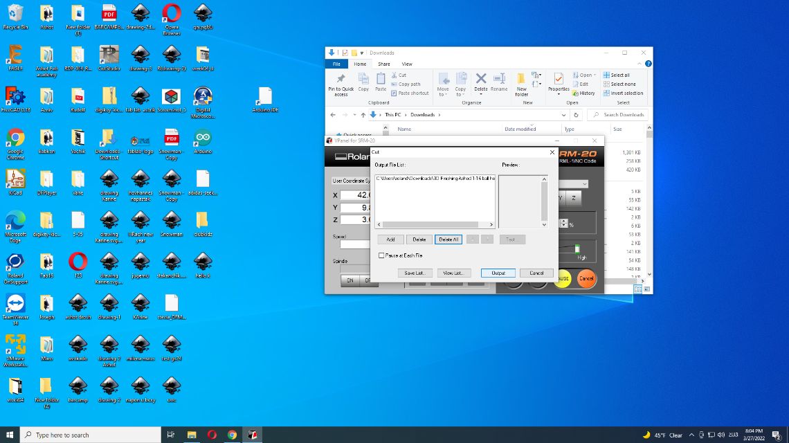
Milling
I started importing the files into the Srm-20 software.


You can see a comparison between the 2.5D cutting and a 3D cutting very well:
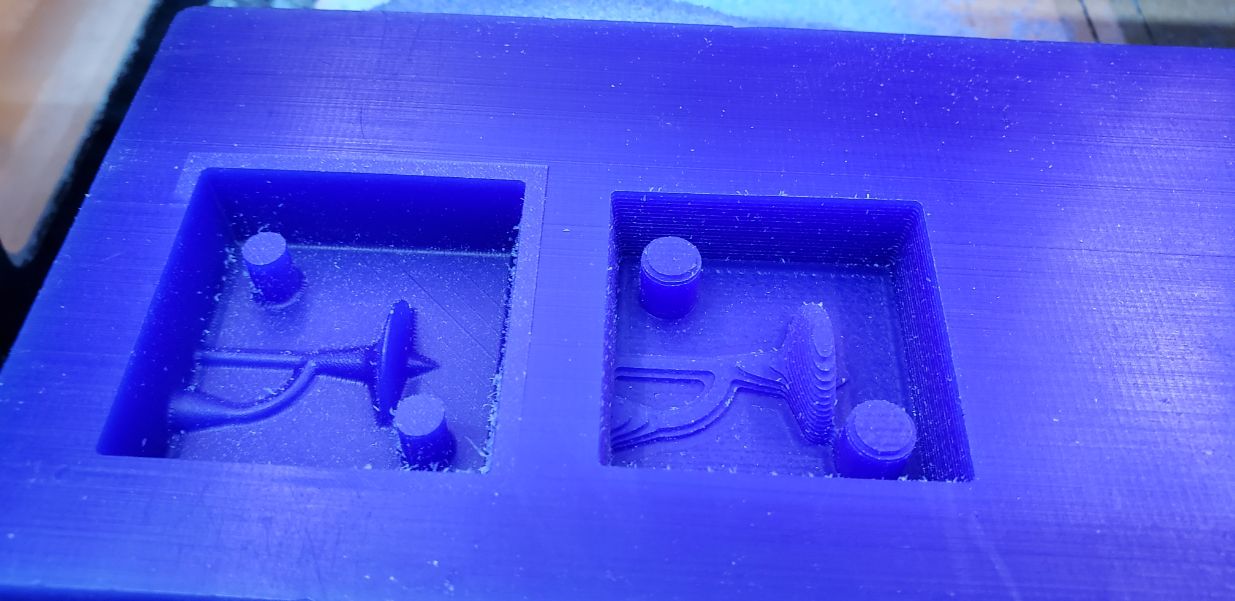
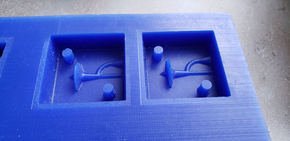
After it I cleaned and recycled everything.
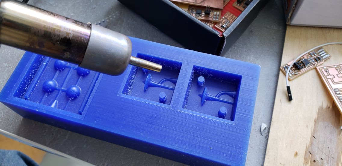
The moulds had a bit of chips and that can affect the final mould
So I used the blower for soldering to get rid of them.
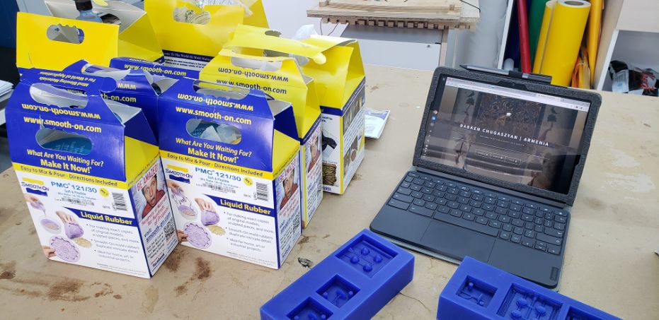
Moulding
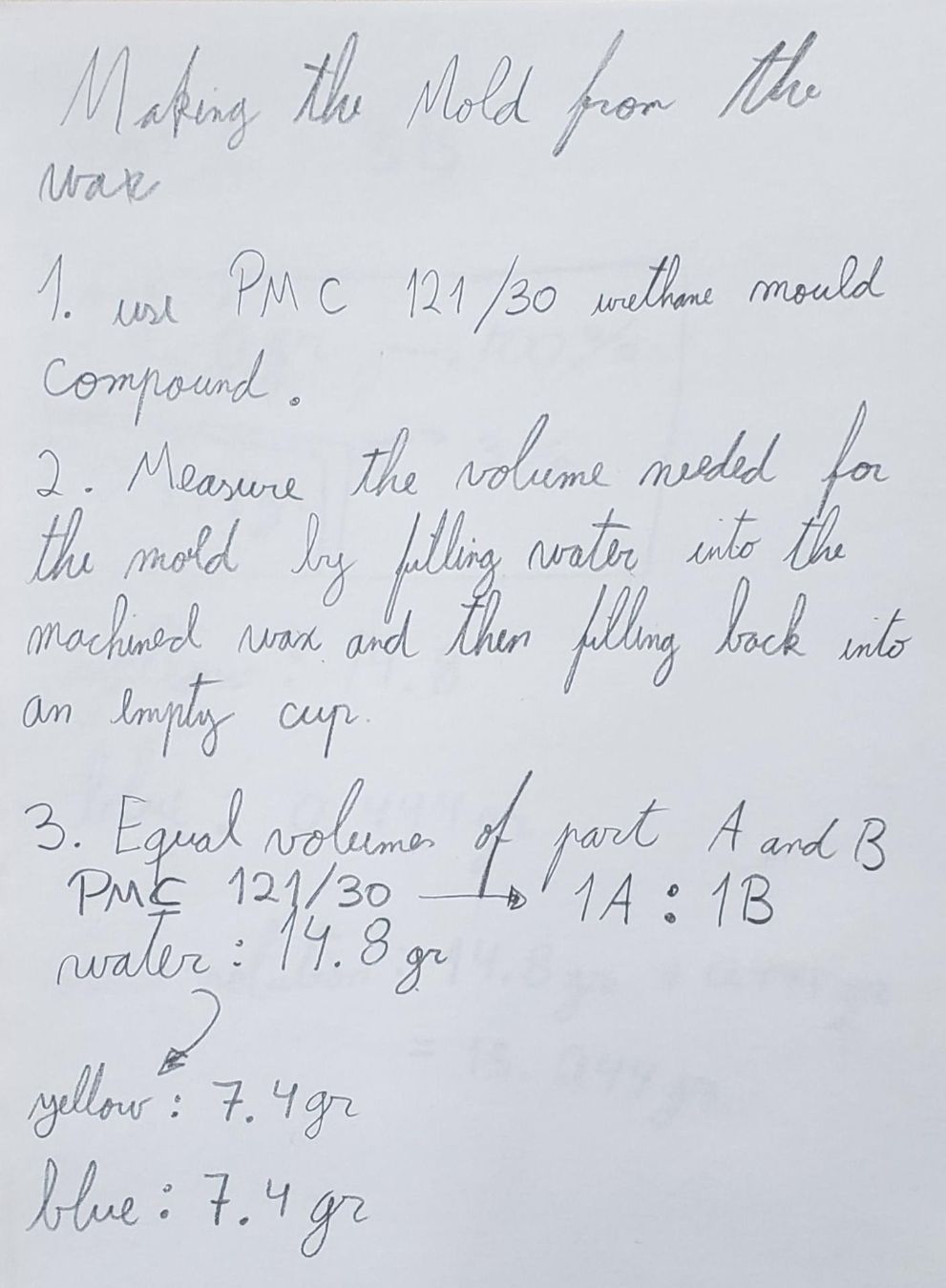
In the beginning I wanted to use the PMC 121/30, but unfortunatelly the yellow jar was solidified.
Any way here are my annotations.
So I changed into the Mold Max 60. You can mould metal with this material. The ratio is 100A:3B
 .
.
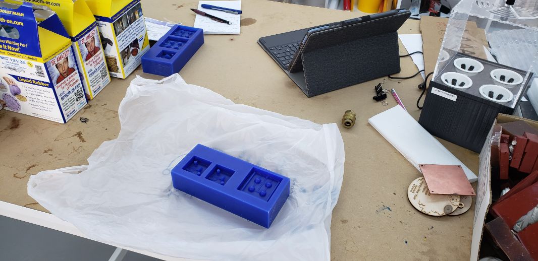
I started the process of moulding:
I put a bag under the mould blocks to not make the table dirty
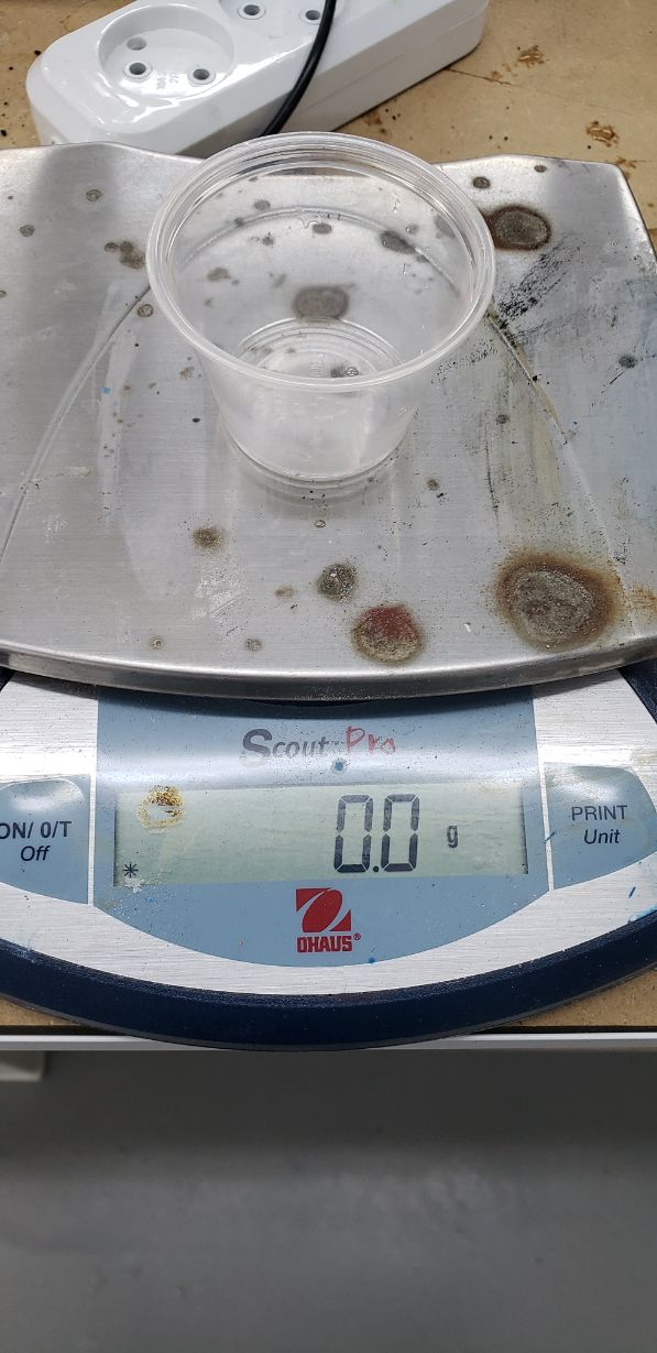
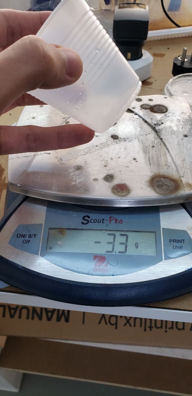
First to measure the volume I took water with a cup and filled into the mould
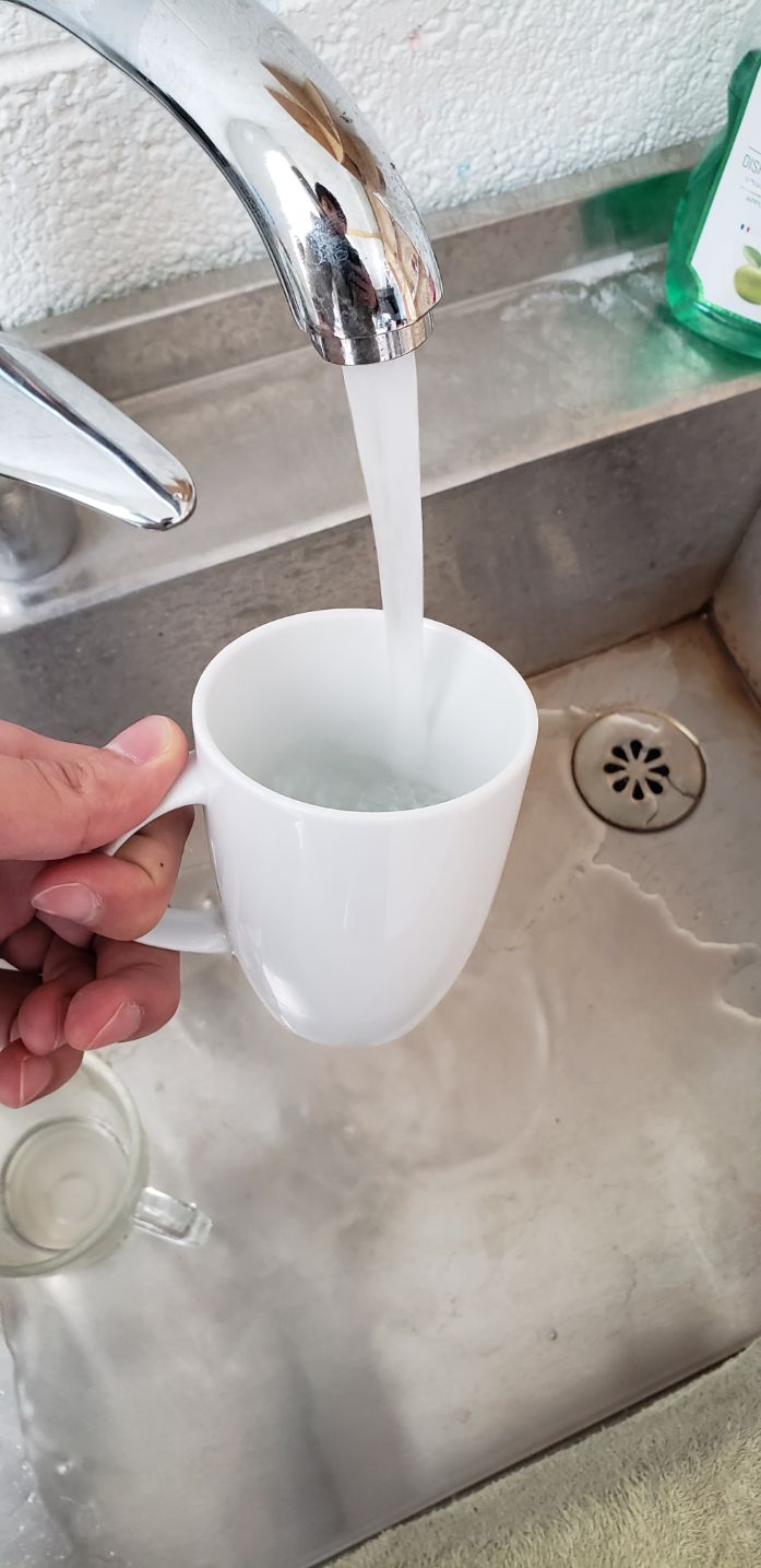
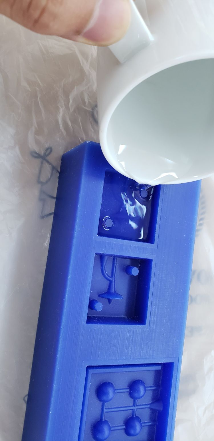
Then with an empty cup I put the water again on it and I measure it.
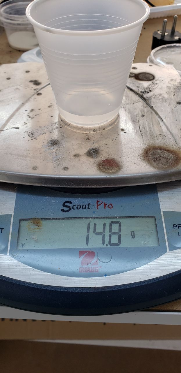
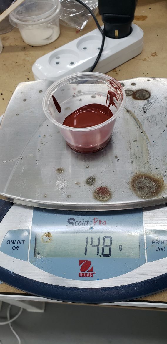
After this I put the same quantity of the red material or the 100A until get into the number of 14.8
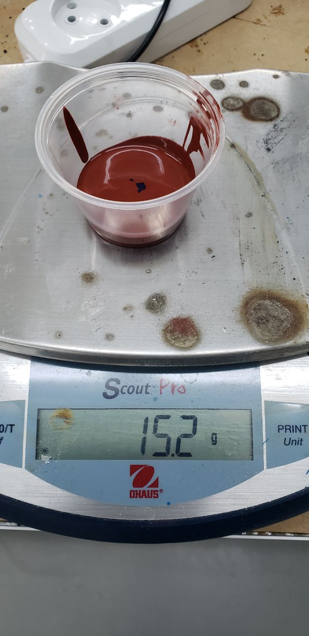
Then I added the 3% of the total for the blue component.
And finally I mixed it horizontally with a cotton bud.
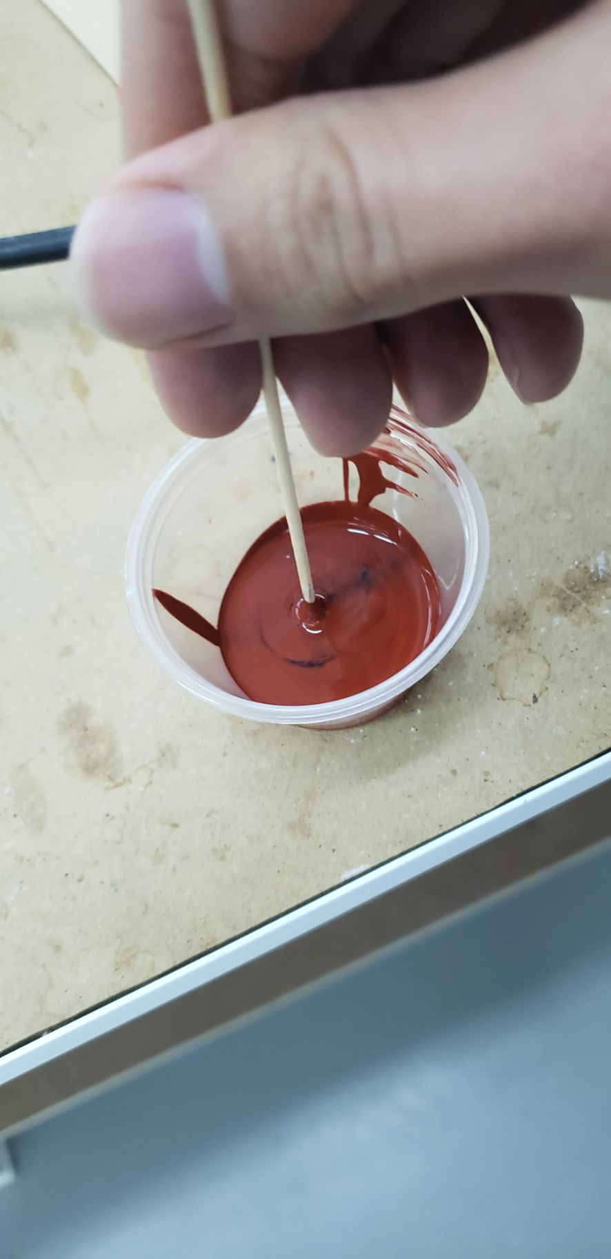
If you have more questions about how to stir, there is a good video (not so known) about how to stir. I took this method from an old video of Neil about “Preparing Rubber for Mould. Please take a look at it, it’s instrumental, and it explains a lot of things about the Moulding and Casting process, as well as how to stir properly without bubbles:
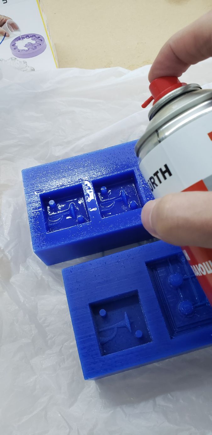
Then I put a little bit of silicone lubricant into the moulds, so they won’t get stick to the machined mould later.
And I put the material into the mould.
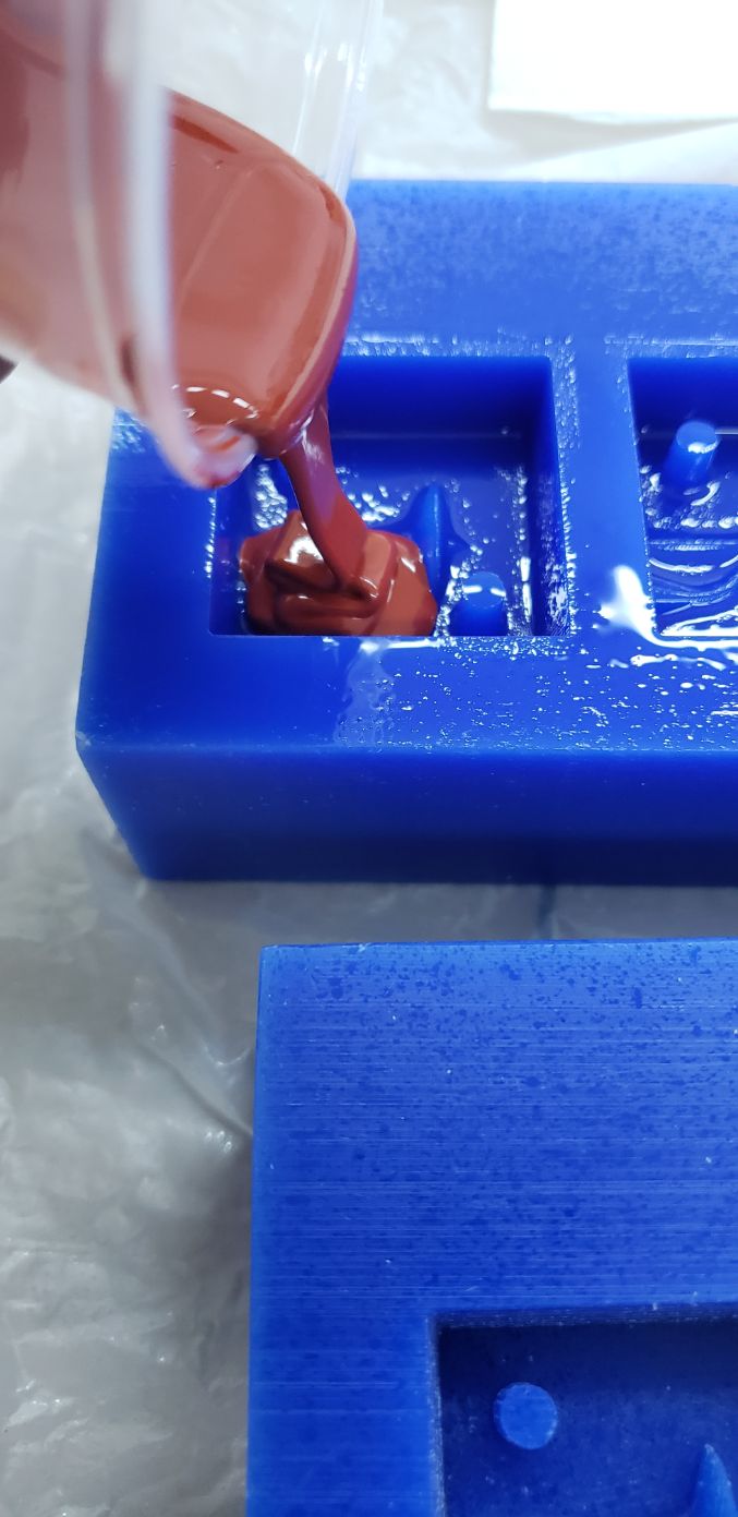
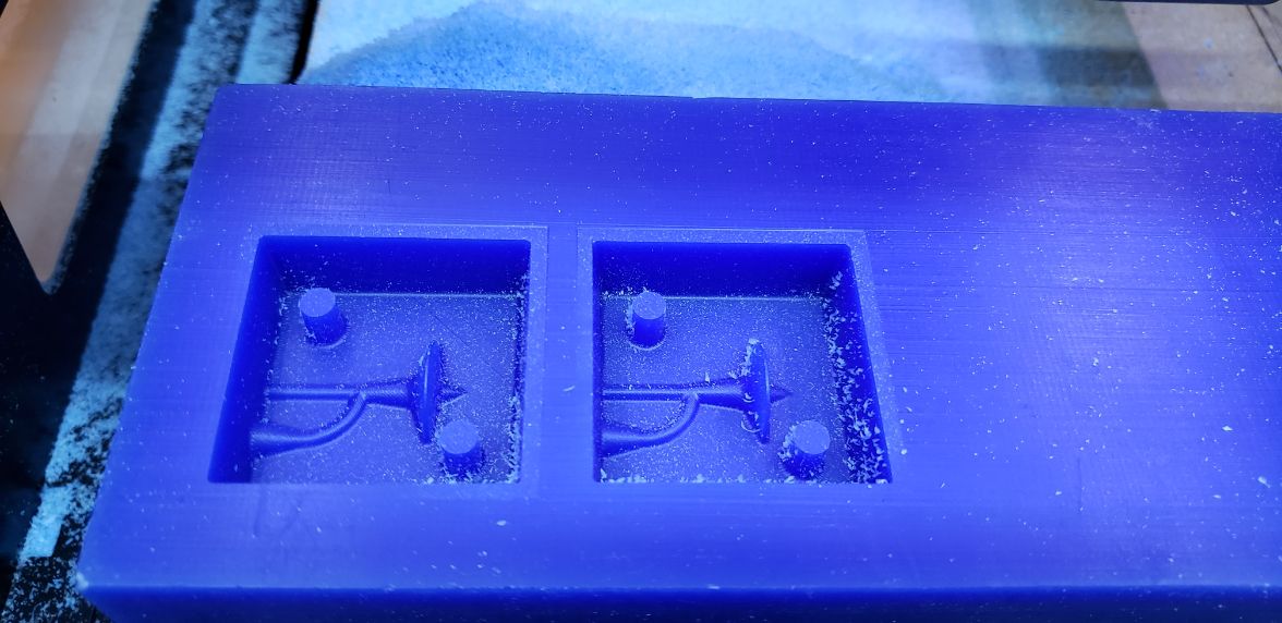
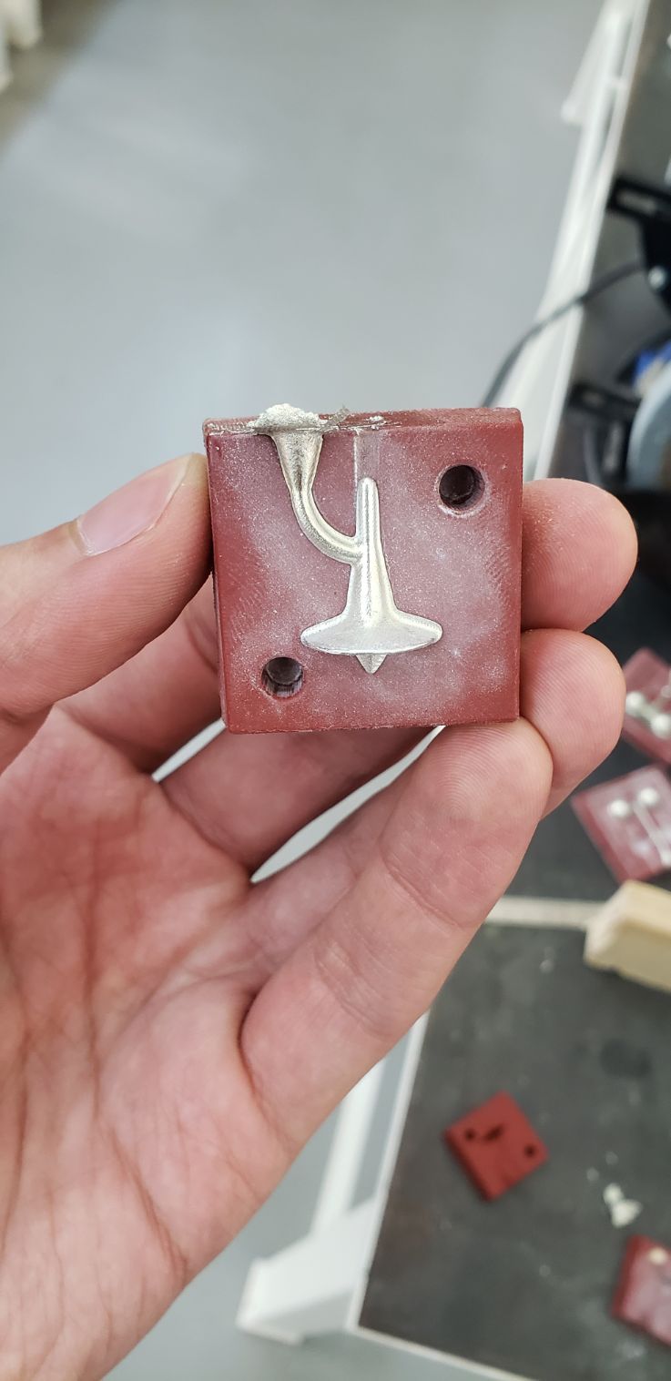
Having a result like this.
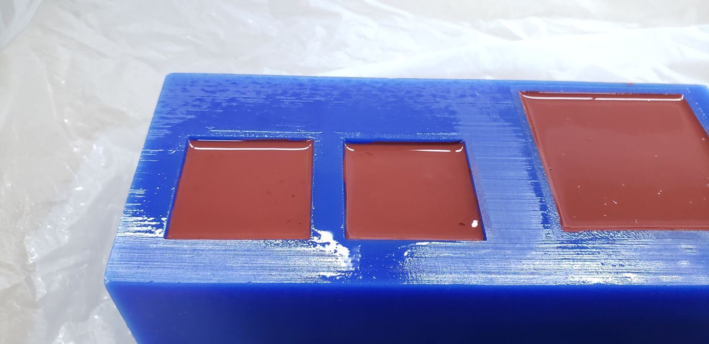
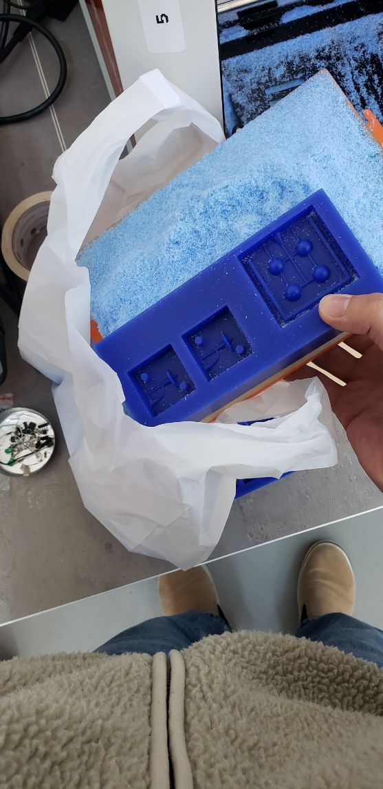
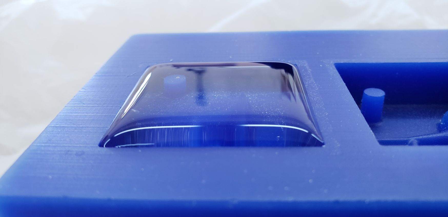
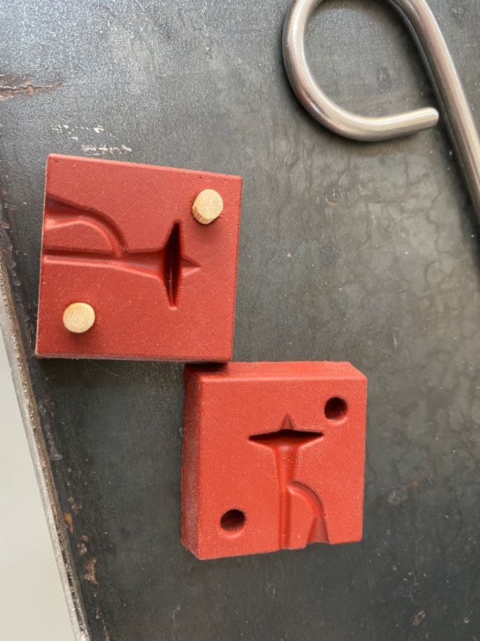
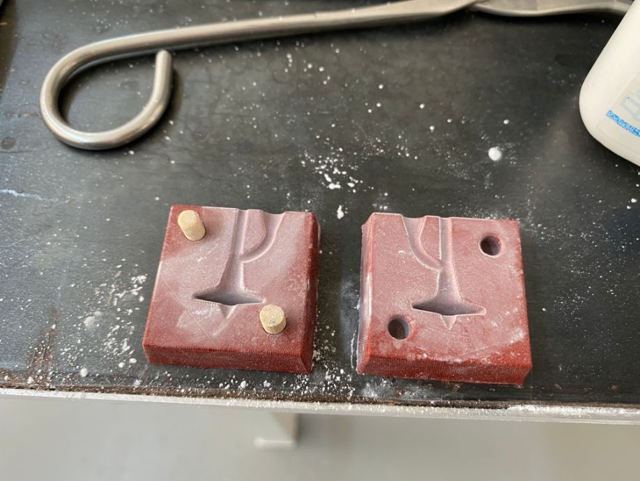
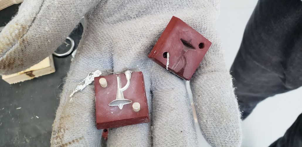
After 24 hours, I had the final result of my mould:
Metal (Babbitt alloy)
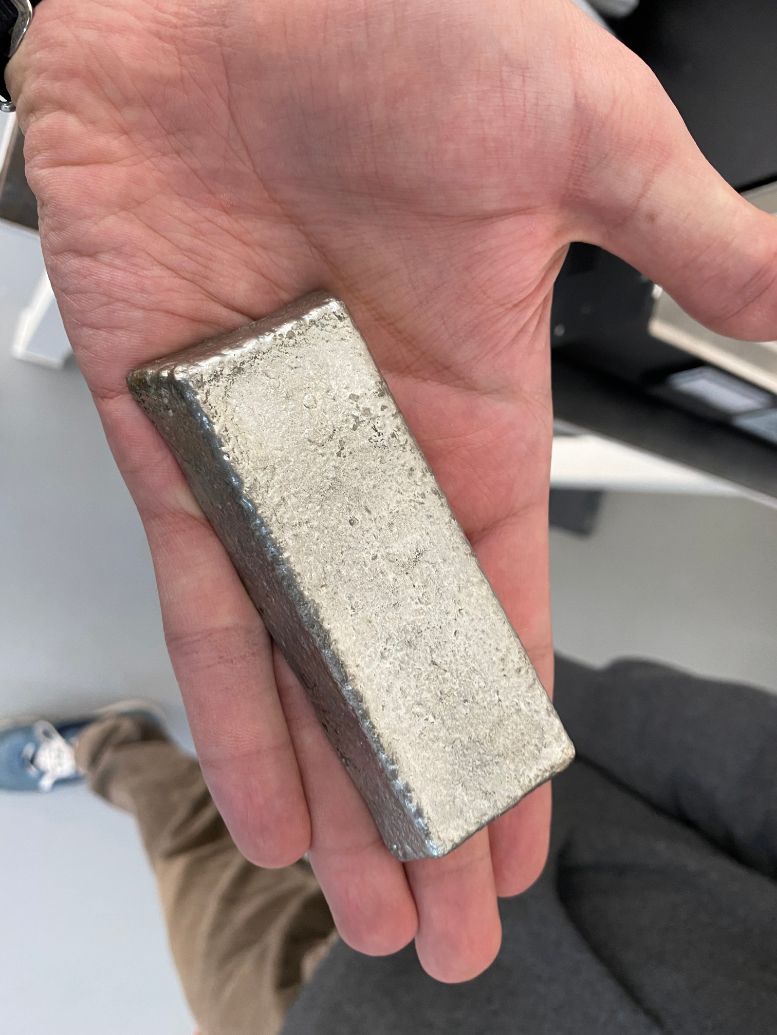
The material that I’m going to use for the metal is called Babbitt, according to the website RotoMetals, the Babbitt that I am using is a Grade 2 which description is:
RotoNickel Babbitt Pewter is a durable Babbitt alloy consisting of approximately 89% Tin, 3.45% Copper, 7.5% Antimony, and .15% of Monel which contains Nickel. Some times called High Speed Nickel Babbitt or 4 times Nickel Babbitt, this Babbitt is suitable for bearings which are exposed to high temperatures and friction. The melting temperature of this alloy is 466°F (241.1111°C) and the proper pouring temperature 795°F (423.8889°C). Each ingot weighs approximately 1 pound and measures 3/4” x 1-1/2” x 4”.
According to Belmontmetals, the SDS or “Safety data sheet” of the babbitt is quite extensive, and its regardless that this metal can be very toxic in its powder form.
| But as we only manipulated the babbitt in its solid and then almost “molten” form, it didn’t release any amount of smoke. |
|---|
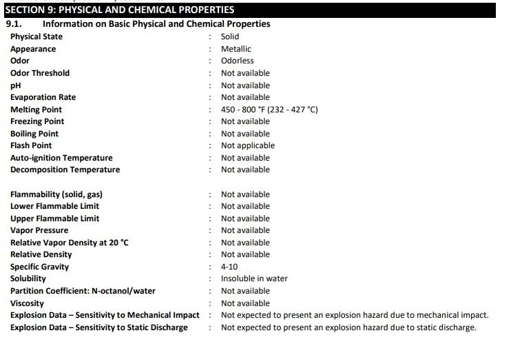 |
| As well as we stayed far from the mortar, due to we were holding it with a pair of tongs for safety porpuses. |
| For this reason, I consider that the best part of all the safety data sheet that I need to highlight is the following: |
|---|
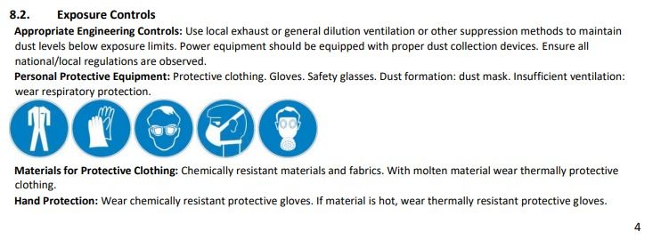 |
| That’s why a pair of gloves and tongs were striclty necessary in our case. |
 |
| (SOURCE: WALLMART) |
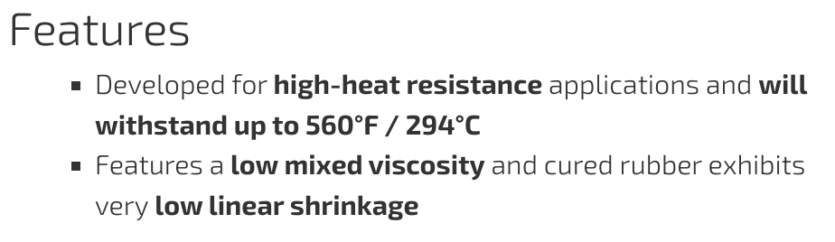
Now according to the website of Smooth-ON: Mold Max™ 60 is a Shore 60A tin catalyzed silicone mold rubber formulated for applications requiring high heat resistance (up to 560°F/294°C).
Now, the interesting thing here, is that the proper pouring temperature of the Babbitt is 424°C and the Mold Max™ 60 heat resistance is up to 294°C. But for some reason the Mold Max 60 heat resistance is superior than the mentioned. And I know this, because Babken’s documentation and because I heat the Babbitt as well, around 350°C and then I poured it to the mould.
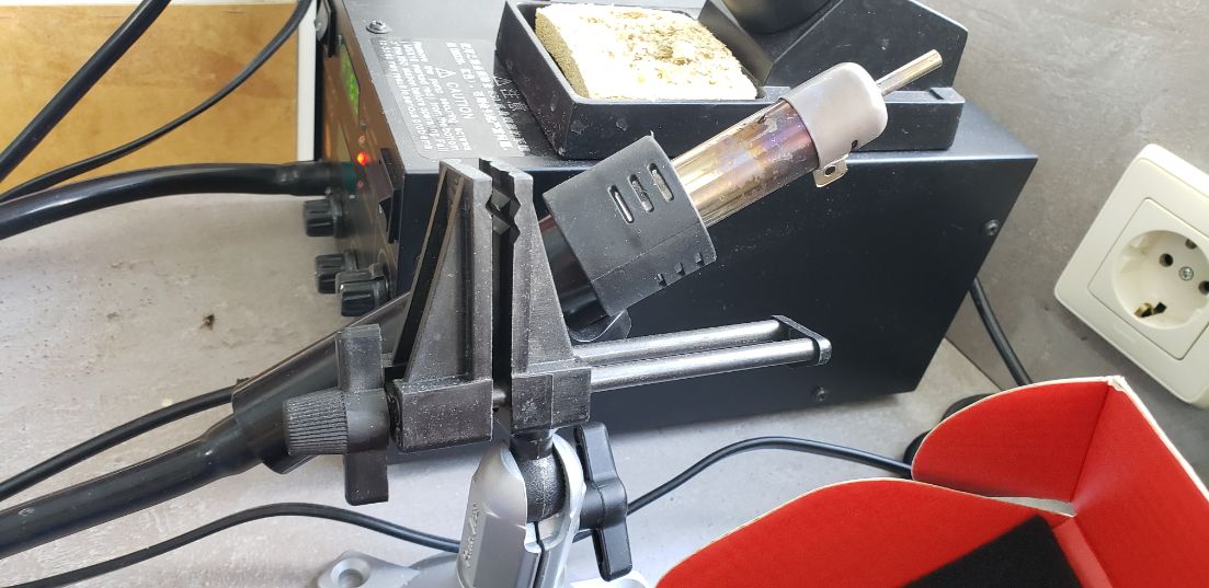
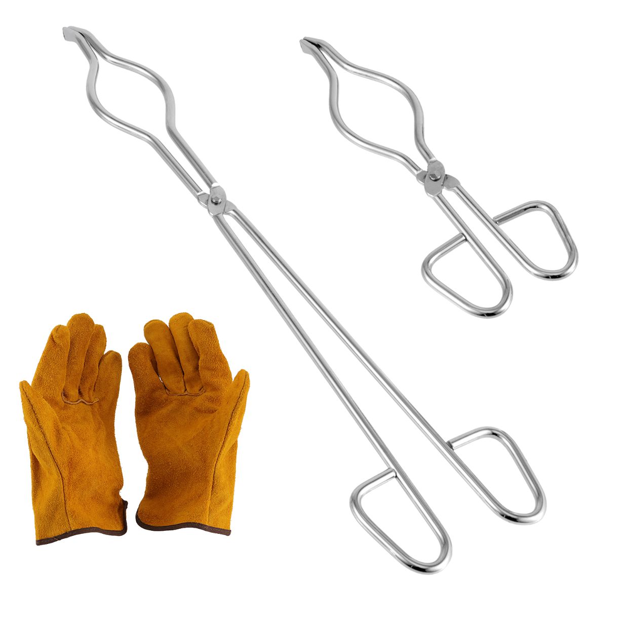
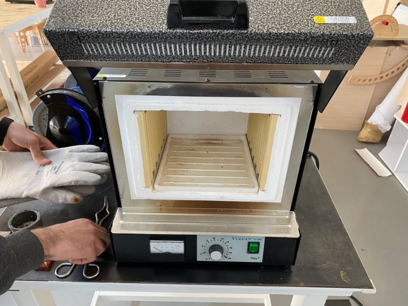
For melting the Babbitt I used a Vulcan A-550:
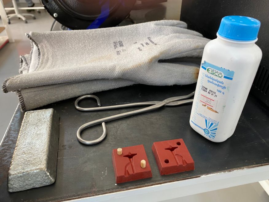
The materials that I used were the following ones:
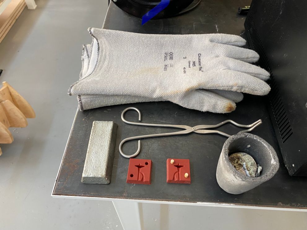
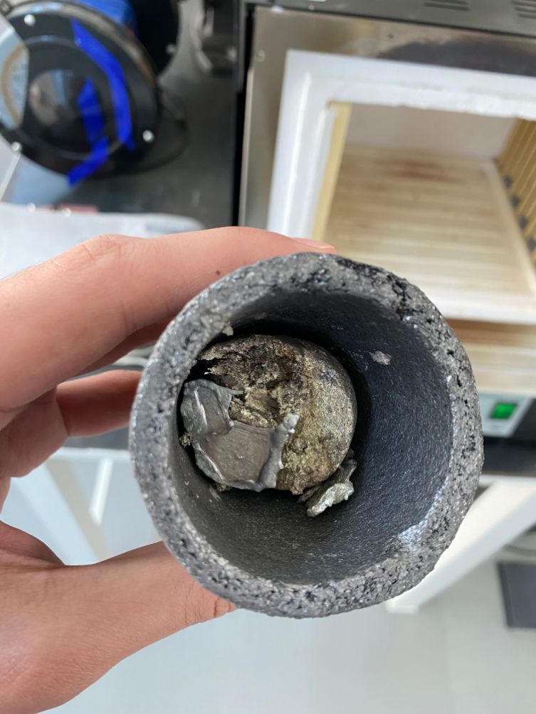
The babbitt is inside of the stone pot that I put inside of the furnace, I didn’t have to wear some protection, because the furnace was turned off.
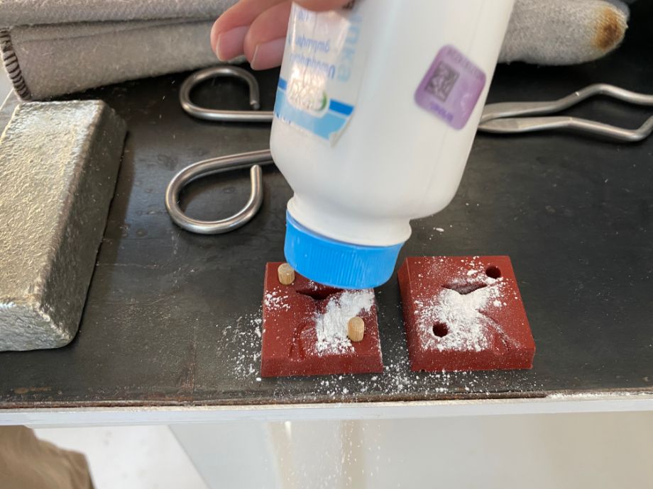
While the Babbitt was getting melted, I took advantage of preparing the mould putting talcum powder on it.
While the Babbit was getting melted, I noticed that some parts weren’t fully melted.
My mentor explained to me that it was because of the oxid that some pieces can present, and that I can easily remove it with a stick or something like that.
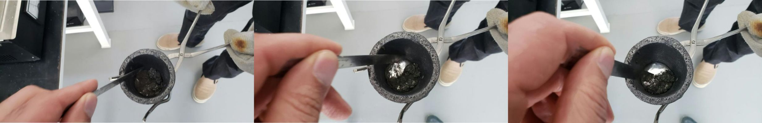
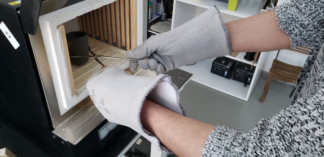
I put the Babbitt in the furnace again and I waited.
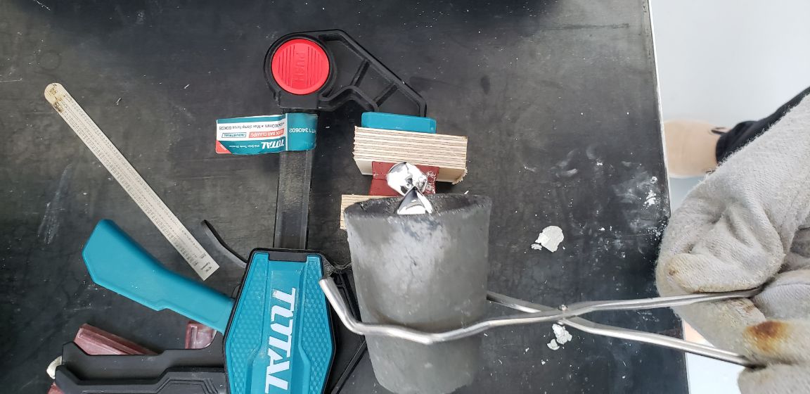
After a couple of minutes I took the melted babbit from the furnace, now with a help of a pair of gloves and the tongs.
After this I poured it into the mould that was held by clambs.
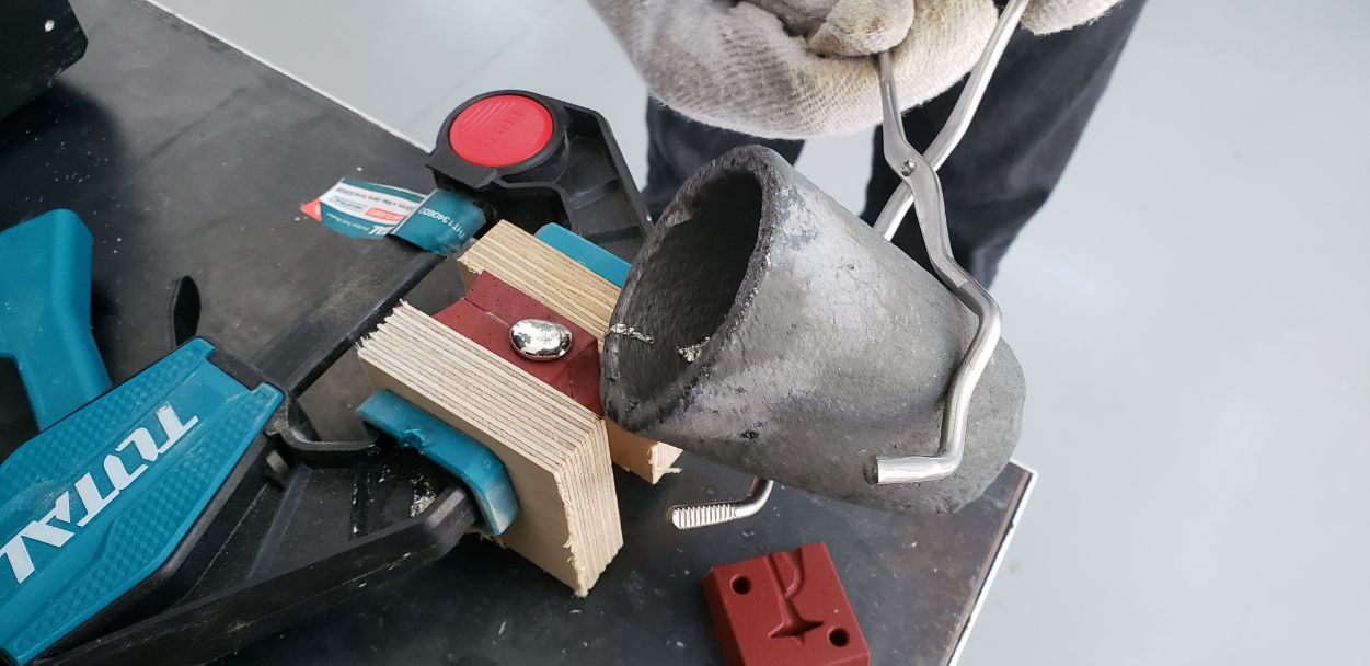
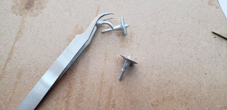
I waited around 10 seconds, again using the pair of gloves and I separated it.
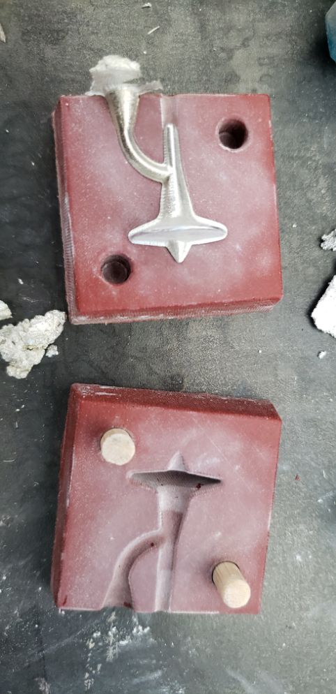
This spinner was not well moulded.
After I cut the funel and sanded some parts it didn’t spin good.
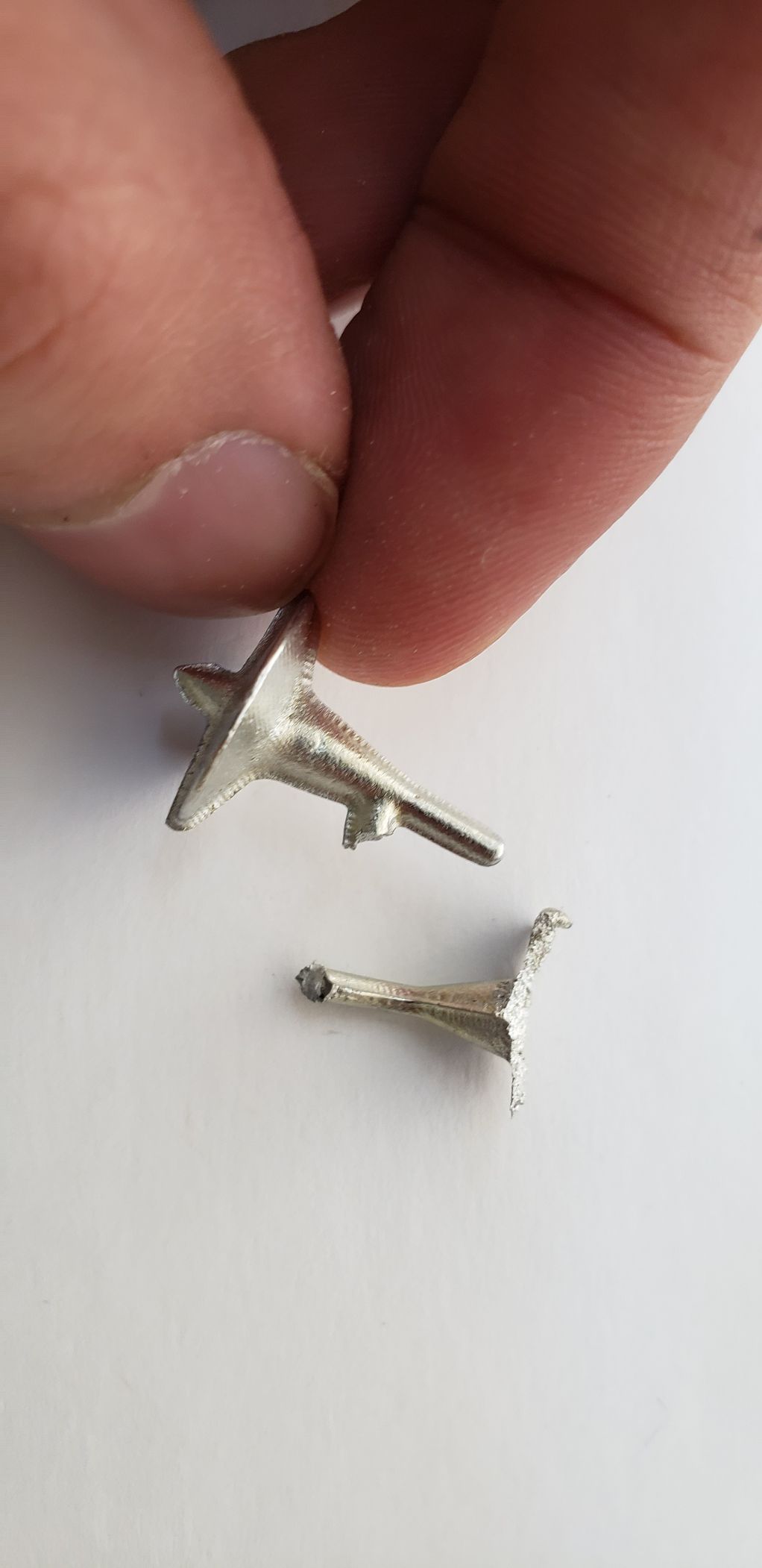
That’s why I repeated the process one more time, and this time, it looked so much better:
Result
Errors
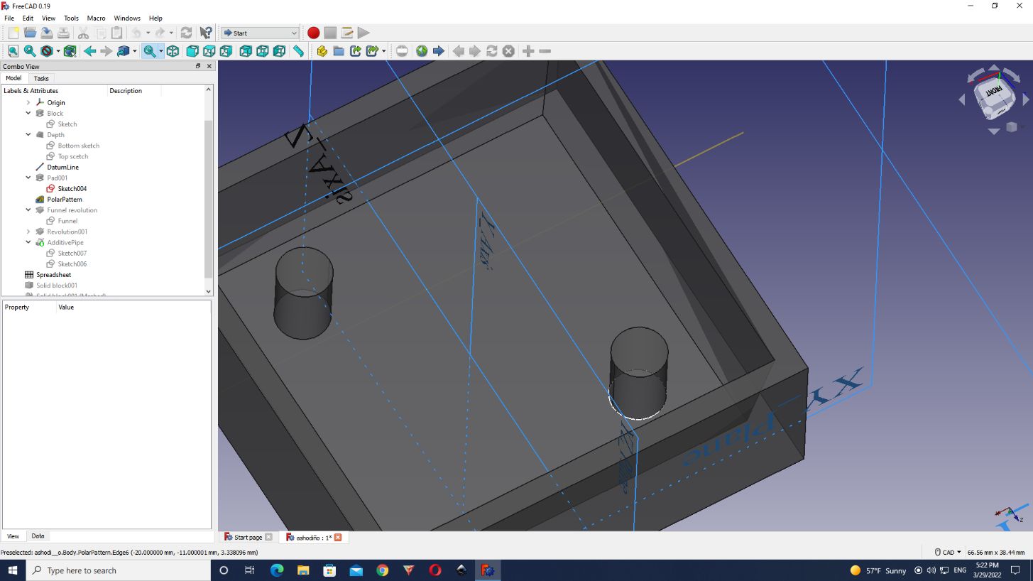
First I took the DatumLine and change It was not necessary to make changes in the “PolarPattern”, FreeCAD automatically change the other pilar.
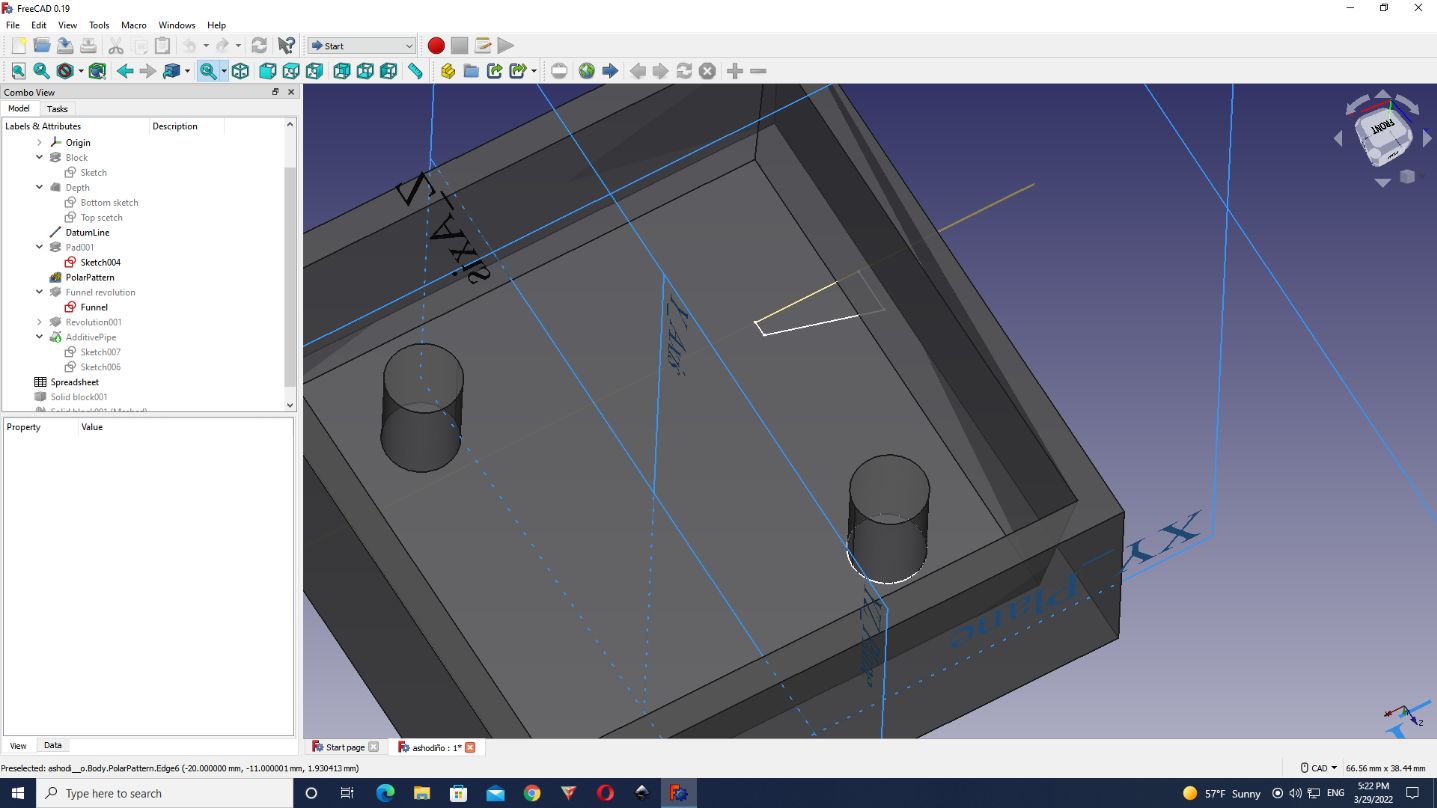
What I had to change is the “AdditivePipe”, because it remained to the original side as it was not attached to the funnel. It was like a type of “continuation”.
I opened the sketch again and tried to do the same thing as I did with the pilar. Just change the parameter.
As the line was created from the semi-circunference, I had to change first the semi-circunference, and then the line, because that value (-7) was considered with the semi-circunference
Downloads
FreeCAD
FCStd
G-Codes
roughing (flat)
finishing (ball head)
STL FILE
Mould