12. Networking and communications
This week was a bit complicated for me, as I needed more knowledge in programming than ever.
I received much help for completing this week.
Group Assignment
If you want to check our group assignment website, you can click here
I was amazed about how the communications between PCBs were possible and the benefits for it as well.
Tons of ideas came through my mind that I want to build. I can work with BlueTooth, Wi-Fi or even create my own server to receive and send information using a PCB that I made. The limitations are small.
This capability of using linked or networking devices is awesome.
I remembered how our teacher Neil pressing just a button from Boston assisted virtually and with a pair of scissors opened Fab Lab Oulu.
Things are incredible when you are connected.
First, I did my research and I found a good tutorial in Youtube about an LED in a breadboard (because I’d never used a breadboard before or something similar).
This is the code that I used
/*
 * Bas on Tech
 * This course is part of the courses on https://arduino-tutorials.net
 *
 * (c) Copyright 2018-2019 - Bas van Dijk / Bas on Tech
 * This code and course is copyrighted. It is not allowed to use these courses commerically
 * without explicit written approval
 *
 * YouTube:    https://www.youtube.com/c/BasOnTech
 * Facebook:   https://www.facebook.com/BasOnTechChannel
 * Instagram:  https://www.instagram.com/BasOnTech
 * Twitter:    https://twitter.com/BasOnTech
 *
 */

// The setup() function only runs when the program starts
void setup() {
  // Initilize the digital pin LED_BUILTIN as output
  pinMode(LED_BUILTIN, OUTPUT);
}

// The loop() function runs infinitely
void loop() {
  digitalWrite(LED_BUILTIN, HIGH);   // Turn the built-in LED on
  delay(1000);                       // Pause for 1 second (1000 milliseconds)

  digitalWrite(LED_BUILTIN, LOW);    // Turn the built-in LED on
  delay(1000);                       // Pause for 1 second (1000 milliseconds)
}
I’m so happy about this, it’s a small start maybe for others, but for me it’s a big step!
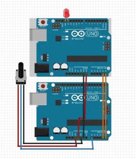
Now, in the websita of Create.Arduino, I found something similar that I was doing but with another Arduino. And as well, in that website, they were talking about the I2C Protocol. Just the thing that I needed!
| These images were taken from the website |
|---|
 |
 |
But this is just a blink, I actually want to send a message.
So I found this cool Youtube video:
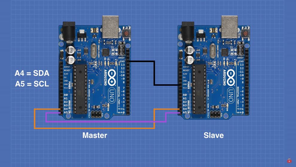
Here I found out things that I never would have known. For example that the simply connection between Arduinos. And as well the following thing:
| Master | to | Slave |
|---|---|---|
| GND | to | GND |
| A4 = SDA (data line) | to | A4 = SDA (data line) |
| Some Arduinos have separate SDA in SCL connection | ||
| A5 = SCL (clock) | to | A5 = SCL (clock) |
Note about the code
The original code had a delay of 50, but in the video it shown the exchange of data (message between the project) very fast, that’s why I deceided to change it to 1000 (that is one second).
The original code for the master is this one:
/*
  I2C Master Demo
  i2c-master-demo.ino
  Demonstrate use of I2C bus
  Master sends character and gets reply from Slave
  DroneBot Workshop 2019
  https://dronebotworkshop.com
*/

// Include Arduino Wire library for I2C
#include <Wire.h>

// Define Slave I2C Address
#define SLAVE_ADDR 9

// Define Slave answer size
#define ANSWERSIZE 5

void setup() {

  // Initialize I2C communications as Master
  Wire.begin();

  // Setup serial monitor
  Serial.begin(9600);
  Serial.println("I2C Master Demonstration");
}

void loop() {
  delay(50);
  Serial.println("Write data to slave");

  // Write a charatre to the Slave
  Wire.beginTransmission(SLAVE_ADDR);
  Wire.write(0);
  Wire.endTransmission();

  Serial.println("Receive data");

  // Read response from Slave
  // Read back 5 characters
  Wire.requestFrom(SLAVE_ADDR,ANSWERSIZE);

  // Add characters to string
  String response = "";
  while (Wire.available()) {
      char b = Wire.read();
      response += b;
  }

  // Print to Serial Monitor
  Serial.println(response);
}
And this is the code for the slave
/*
  I2C Slave Demo
  i2c-slave-demo.ino
  Demonstrate use of I2C bus
  Slave receives character from Master and responds
  DroneBot Workshop 2019
  https://dronebotworkshop.com
*/

// Include Arduino Wire library for I2C
#include <Wire.h>

// Define Slave I2C Address
#define SLAVE_ADDR 9

// Define Slave answer size
#define ANSWERSIZE 5

// Define string with response to Master
String answer = "Hello";

void setup() {

  // Initialize I2C communications as Slave
  Wire.begin(SLAVE_ADDR);

  // Function to run when data requested from master
  Wire.onRequest(requestEvent);

  // Function to run when data received from master
  Wire.onReceive(receiveEvent);

  // Setup Serial Monitor
  Serial.begin(9600);
  Serial.println("I2C Slave Demonstration");
}

void receiveEvent() {

  // Read while data received
  while (0 < Wire.available()) {
    byte x = Wire.read();
  }

  // Print to Serial Monitor
  Serial.println("Receive event");
}

void requestEvent() {

  // Setup byte variable in the correct size
  byte response[ANSWERSIZE];

  // Format answer as array
  for (byte i=0;i<ANSWERSIZE;i++) {
    response[i] = (byte)answer.charAt(i);
  }

  // Send response back to Master
  Wire.write(response,sizeof(response));

  // Print to Serial Monitor
  Serial.println("Request event");
}

void loop() {

  // Time delay in loop
  delay(50);
}
You can find more information in the webiste of the Youtube creator
| Here are some useful infographics |
|---|
 |
 |
And here is my video:
Later, I tried to do something with LCD.
For this, I modified the code a bit.
The code for the Master is this one
/*
  I2C Master Demo
  i2c-master-demo.ino
  Demonstrate use of I2C bus
  Master sends character and gets reply from Slave
  DroneBot Workshop 2019
  https://dronebotworkshop.com
*/

// Include Arduino Wire library for I2C
#include <Wire.h>

// Define Slave I2C Address
#define SLAVE_ADDR 9

// Define Slave answer size
#define ANSWERSIZE 5

void setup() {

  // Initialize I2C communications as Master
  Wire.begin();

  // Setup serial monitor
  Serial.begin(9600);
  Serial.println("I2C Master Demonstration");
}

void loop() {
  delay(5000);
  Serial.println("Write data to slave");

  // Write a charatre to the Slave
  Wire.beginTransmission(SLAVE_ADDR);
  Wire.write(0);
  Wire.endTransmission();

  Serial.println("Receive data");

  // Read response from Slave
  // Read back 5 characters
  Wire.requestFrom(SLAVE_ADDR,ANSWERSIZE);

  // Add characters to string
  String response = "";
  while (Wire.available()) {
      char b = Wire.read();
      response += b;
  }

  // Print to Serial Monitor
  Serial.println(response);
}
The code for Slave is this one
/*
  I2C Slave Demo
  i2c-slave-demo.ino
  Demonstrate use of I2C bus
  Slave receives character from Master and responds
  DroneBot Workshop 2019
  https://dronebotworkshop.com
*/


#include <LiquidCrystal_I2C.h>

LiquidCrystal_I2C lcd(0x27,20,4);  // set the LCD address to 0x27 for a 16 chars and 2 line display


// Include Arduino Wire library for I2C
#include <Wire.h>

// Define Slave I2C Address
#define SLAVE_ADDR 9

// Define Slave answer size
#define ANSWERSIZE 5

// Define string with response to Master
String answer = "Hello";

void setup() {

  lcd.init();                      // initialize the lcd

    lcd.backlight();
  lcd.setCursor(0,0);


  // Initialize I2C communications as Slave
  Wire.begin(SLAVE_ADDR);

  // Function to run when data requested from master
  Wire.onRequest(requestEvent);

  // Function to run when data received from master
  Wire.onReceive(receiveEvent);

  // Setup Serial Monitor
  Serial.begin(9600);
  Serial.println("I2C Slave Demonstration");
}


void receiveEvent() {

  // Read while data received
  while (0 < Wire.available()) {
    byte x = Wire.read();
  }

  // Print to Serial Monitor
  Serial.println("Receive event");

}

void requestEvent() {

  // Setup byte variable in the correct size
  byte response[ANSWERSIZE];

  // Format answer as array
  for (byte i=0;i<ANSWERSIZE;i++) {
    response[i] = (byte)answer.charAt(i);
  }

  // Send response back to Master
  Wire.write(response,sizeof(response));

  // Print to Serial Monitor
  Serial.println("Request event");

}


void loop() {


  lcd.print("H");
  lcd.print("e");
  lcd.print("l");
  lcd.print("l");
  lcd.print("o");


  // Time delay in loop
  delay(5000);
}
Note about Arduino IDE
Did you know that you can open 2 different Arduino IDE projects, and work at the same time in the same computer? For example I worked with the “Master” and the “Slave” using different COM.
Here is the video:
Step 1: Getting the code
So the first thing I needed to do was to look for a specific program code called “LiquidcRYSTAL_I2C”. And of course, one of my questions was “What does it mean I2C and what is it made for?”
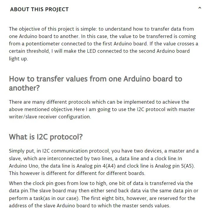
What is I2C?
According to the page TotalPhase.com:
The I2C protocol is used to establish communication between two or more ICs (Integrated Circuits), hence why it’s known as Inter-Integrated Circuit (I2C) communication. However, it should be noted that I2C could also be used as a communication protocol between two ICs that are located on the same PCB.
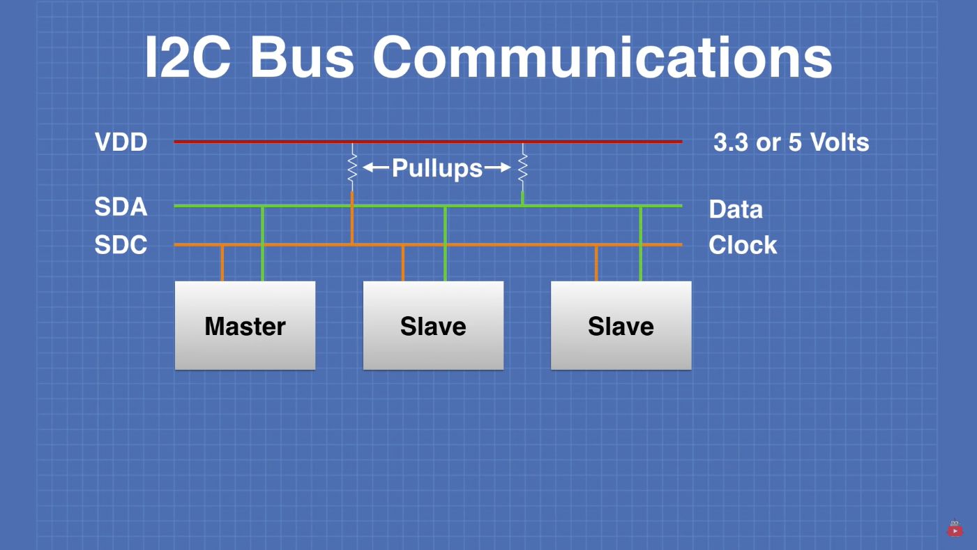
Where and how is it used?
In short, when you need to establish short distance communication within the same board or device, you can use I2C. It requires only two bidirectional wires for transmitting and receiving information. You also need to know that I2C protocol supports serial communication only. The protocol is very popular and multiple peripheral ICs are connected in master-slave configurations. Talking about master-slave configuration, you have a lot of flexibility when it comes to using the I2C protocol. I2C allows designers to establish two-way communication between multiple master ICs and slave ICs. In fact, you can connect as many as 1008 slave devices.
So it is all set! I2C allows to establish two-way communication between multiple master (my pcb in my case) and slave (the arduino that I’m going to use)
First the echo-hello button code
So, for having an idea how it might work the code, I programmed my PCB with the following code, just for testing wether the PCB will send something like a “message” with an actionable button
First I upload the code in my PCB:
And then I tested it the Arduino IDE software
Code for the Chi-le (echo.hello.button)
//
//
// hello.button.45.c
//
// button hello-world
//    9600 baud FTDI interface
//
// Neil Gershenfeld
// 10/31/10
//
// (c) Massachusetts Institute of Technology 2010
// This work may be reproduced, modified, distributed,
// performed, and displayed for any purpose. Copyright is
// retained and must be preserved. The work is provided
// as is; no warranty is provided, and users accept all
// liability.
//

#include <avr/io.h>
#include <util/delay.h>

#define output(directions,pin) (directions |= pin) // set port direction for output
#define input(directions,pin) (directions &= (~pin)) // set port direction for input
#define set(port,pin) (port |= pin) // set port pin
#define clear(port,pin) (port &= (~pin)) // clear port pin
#define pin_test(pins,pin) (pins & pin) // test for port pin
#define bit_test(byte,bit) (byte & (1 << bit)) // test for bit set
#define bit_delay_time 102 // bit delay for 9600 with overhead
#define bit_delay() _delay_us(bit_delay_time) // RS232 bit delay
#define half_bit_delay() _delay_us(bit_delay_time/2) // RS232 half bit delay

#define input_port PORTB
#define input_direction DDRB
#define input_pin (1 << PB4)
#define input_pins PINB
#define serial_port PORTB
#define serial_direction DDRB
#define serial_pin_out (1 << PB1)

void put_char(volatile unsigned char *port, unsigned char pin, char txchar) {
   //
   // send character in txchar on port pin
   //    assumes line driver (inverts bits)
   //
   // start bit
   //
   clear(*port,pin);
   bit_delay();
   //
   // unrolled loop to write data bits
   //
   if bit_test(txchar,0)
      set(*port,pin);
   else
      clear(*port,pin);
   bit_delay();
   if bit_test(txchar,1)
      set(*port,pin);
   else
      clear(*port,pin);
   bit_delay();
   if bit_test(txchar,2)
      set(*port,pin);
   else
      clear(*port,pin);
   bit_delay();
   if bit_test(txchar,3)
      set(*port,pin);
   else
      clear(*port,pin);
   bit_delay();
   if bit_test(txchar,4)
      set(*port,pin);
   else
      clear(*port,pin);
   bit_delay();
   if bit_test(txchar,5)
      set(*port,pin);
   else
      clear(*port,pin);
   bit_delay();
   if bit_test(txchar,6)
      set(*port,pin);
   else
      clear(*port,pin);
   bit_delay();
   if bit_test(txchar,7)
      set(*port,pin);
   else
      clear(*port,pin);
   bit_delay();
   //
   // stop bit
   //
   set(*port,pin);
   bit_delay();
   //
   // char delay
   //
   bit_delay();
   }
void put_string(volatile unsigned char *port, unsigned char pin, char *str) {
   //
   // print a null-terminated string
   //
   static int index;
   index = 0;
   do {
      put_char(port, pin, str[index]);
      ++index;
      } while (str[index] != 0);
   }
int main(void) {
   //
   // main
   //
   // set clock divider to /1
   //
   CLKPR = (1 << CLKPCE);
   CLKPR = (0 << CLKPS3) | (0 << CLKPS2) | (0 << CLKPS1) | (0 << CLKPS0);
   //
   // initialize pins
   //
   set(serial_port, serial_pin_out);
   output(serial_direction, serial_pin_out);
   set(input_port, input_pin); // turn on pull-up
   input(input_direction, input_pin);
   //
   // main loop
   //
   while (1) {
      //
      // wait for button down
      //
      while (0 != pin_test(input_pins,input_pin))
         ;
      put_string(&serial_port, serial_pin_out, "Chi");

      //
      // wait for button up
      //
      while (0 == pin_test(input_pins,input_pin))
         ;
      put_string(&serial_port, serial_pin_out, "le");
      }
   }
Finding the code for LiquidcRYSTAL_I2C
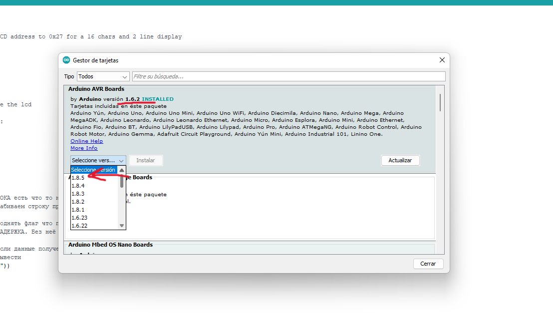
Finding a code for my assignment was a bit difficult, and it’s all resumed because I’m using Windows 11. So there are some problems of compatibilities with Arduino IDE.
A simple but annoying problem:
One problem that took me a while to solve was the constant colapse of the programmer and as well the program at the moment of submitting it.
One good solution that I found was to “downgrade” the software Arduino IDE. And problem solved!
| As you can see in the image, the last version for Arduino IDE is the 1.8.5 |
|---|
| But I have the version 1.6.2 installed |
 |
Code LiquidcRYSTAL_I2C
This is the code for the LiquidCrystal_I2C that I used
/*
 * Displays text sent over the serial port (e.g. from the Serial Monitor) on
 * an attached LCD.
 * YWROBOT
 *Compatible with the Arduino IDE 1.0
 *Library version:1.1
 */
#include <Wire.h>
#include <LiquidCrystal_I2C.h>

LiquidCrystal_I2C lcd(0x27,20,4);  // set the LCD address to 0x27 for a 16 chars and 2 line display

void setup()
{
  lcd.init();                      // initialize the lcd
  lcd.backlight();
  Serial.begin(9600);
}

void loop()
{
  // when characters arrive over the serial port...
  if (Serial.available()) {
    // wait a bit for the entire message to arrive
    delay(100);
    // clear the screen
    lcd.clear();
    // read all the available characters
    while (Serial.available() > 0) {
      // display each character to the LCD
      lcd.write(Serial.read());
    }
  }
}
Receive text from Serial to string
Now I needed to add another piece of the code for making the serial that I’m going to send “readable”.
A person of Fab Lab found this website of a russian guy called Alex Gyver and in this website we found the right part that we had missing.
Code
/*
  Данный код позволяет принять данные, идущие из порта, в строку (String) без "обрывов"
*/
String strData = "";
boolean recievedFlag;
void setup() {
  Serial.begin(9600);
}
void loop() {
  while (Serial.available() > 0) {         // ПОКА есть что то на вход
    strData += (char)Serial.read();        // забиваем строку принятыми данными
    recievedFlag = true;                   // поднять флаг что получили данные
    delay(2);                              // ЗАДЕРЖКА. Без неё работает некорректно!
  }
  if (recievedFlag) {                      // если данные получены
    Serial.println(strData);               // вывести
    strData = "";                          // очистить
    recievedFlag = false;                  // опустить флаг
  }
}
Mixing all together
After having both codes we started to get rid off the things that were unnecessary, and keeping and modifying the parts that we were going to use.
After the modifications the code looked like this:
#include <Wire.h>
#include <LiquidCrystal_I2C.h>

LiquidCrystal_I2C lcd(0x27,20,4);  // set the LCD address to 0x27 for a 16 chars and 2 line display

String strData = "";
boolean recievedFlag;

void setup()
{
   Serial.begin(9600);
  lcd.init();                      // initialize the lcd
  lcd.init();
    // if there's any serial available, read it:
  // Print a message to the LCD.
  lcd.backlight();
  lcd.setCursor(0,0);
}


bool n= 1;
void loop() {
  while (Serial.available() > 0) {         // ПОКА есть что то на вход
    strData += (char)Serial.read();        // забиваем строку принятыми данными
    strData.trim();
    recievedFlag = true;                   // поднять флаг что получили данные
    delay(2);                              // ЗАДЕРЖКА. Без неё работает некорректно!
  }
  if (recievedFlag) {                      // если данные получены
    Serial.println(strData);               // вывести
    if(!(strData == "clear" || strData == "newl"))
    lcd.print(strData);
     if (strData == "clear")
    lcd.clear();
    if (strData == "newl"){
    lcd.setCursor(0,n);
    lcd.print("                            ");
    lcd.setCursor(0,n);
    n=!n;
    }
    strData = "";                          // очистить
    recievedFlag = false;                  // опустить флаг
  }
}
Set-up
Now I have to connect all the wires to the correct pins (or pinout).
| Actually it was not necessary to look for the pins for the LCD, because in the back it came with all the information: |
|---|
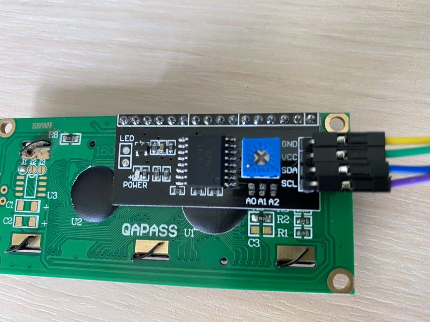 |
I just see the pin names and connect the pins of the LCD to the same pins of the Arduino. This was very easy.
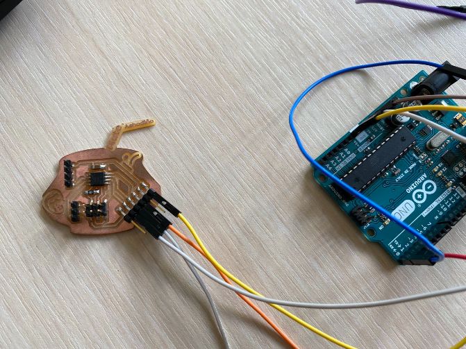
| Now for the PCB to the Arduino, I used the other GND pin of Arduino and I used the 3.3V pin of Arduino to “give power” to my PCB. |
|---|
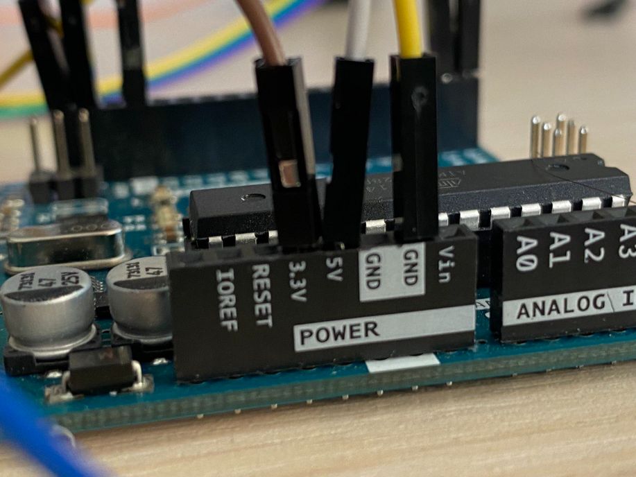 |
Note about the connections
Arduino has only two “V” available. The 5V pin and the 3.3V pin.
The 5V pin was already used by the LCD. That’s why I connected the PCB in the 3.3V pin.
| And for transmiting and receiving information I needed to connect the RX and TX pins to the TX and RX pins of my PCB respectively: |
|---|
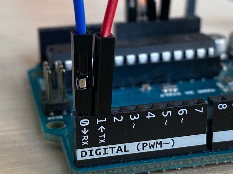 |
 |
So basically the connection was like this:
| PCB | to | Arduino |
|---|---|---|
| VCC | to | VCC |
| GND | to | GND |
| TX | to | RX |
| RX | to | TX |
In this video you can watch how this networking operates:
Downloads
PCB
You can find the PCB design and download files through my assignments as well