3. Computer controlled cutting
Group Assignment
This is the link to our group assignment website.
We experimented the different parameters in the machine properties, playing and chaning focus, power, speed, and frequency.

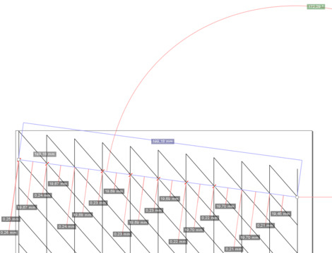
For the kerf what I did was measuring this way.
Making eleven (11) cuts and measuring the size of the last line (the gap between the rectangle and the border)

1. Vinyl Cutter
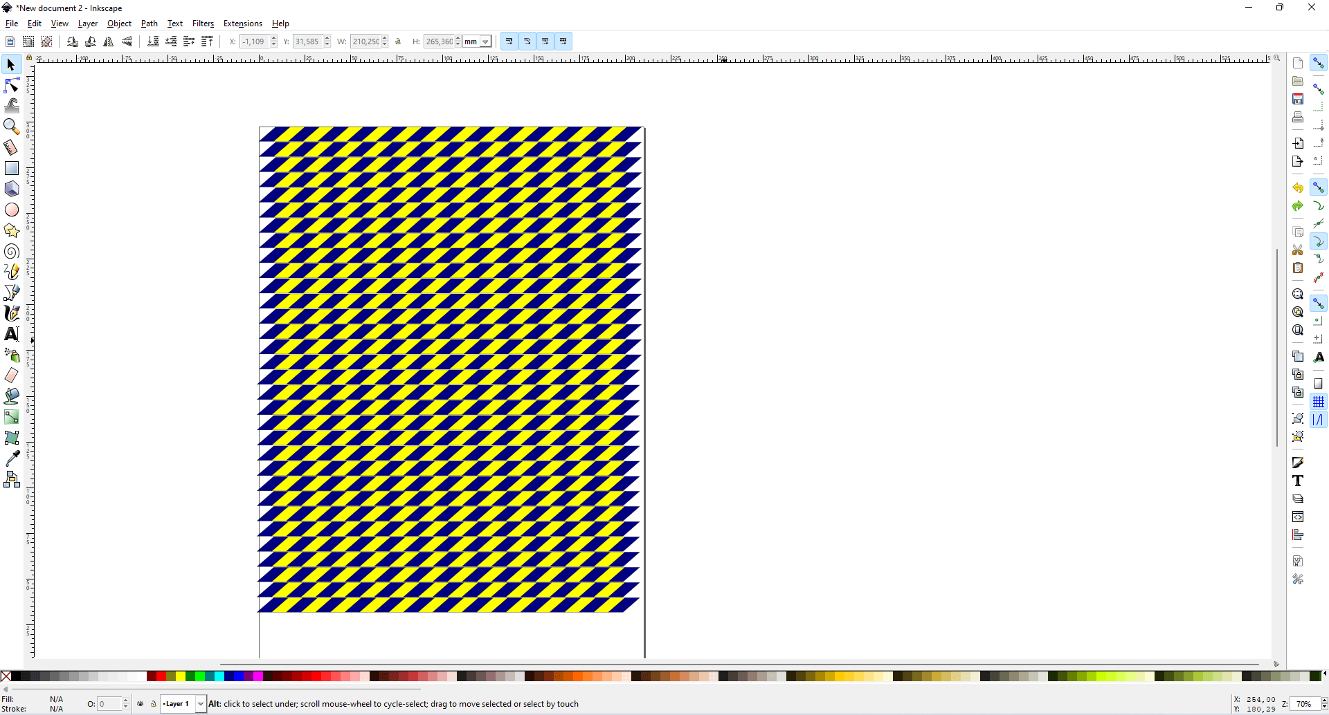
We wanted to put a tape in the floor for the laser cut machine, so the zone of it will be determined. For this reason we are going to use the software inkscape for working.
After choosing the colour and imitating the typical “danger zone” tapes, we finished the design with something like this:
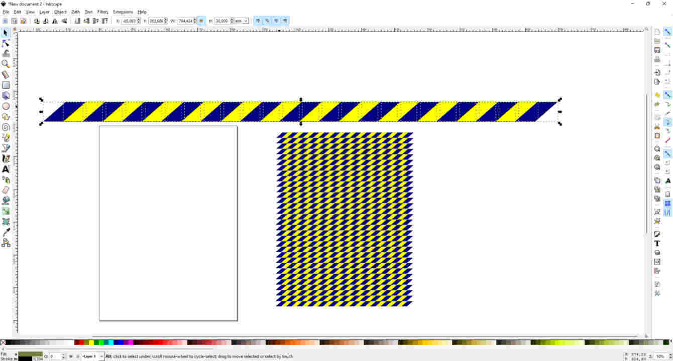
Once the image and design were ready, it was time to scale it to the size (large x wide).
We decided 3cm x 110cm As in Inkscape we worked with milimeters, we had to convert the unit of measurement.
When it was ready to print, an inconvenient happened.
Important note
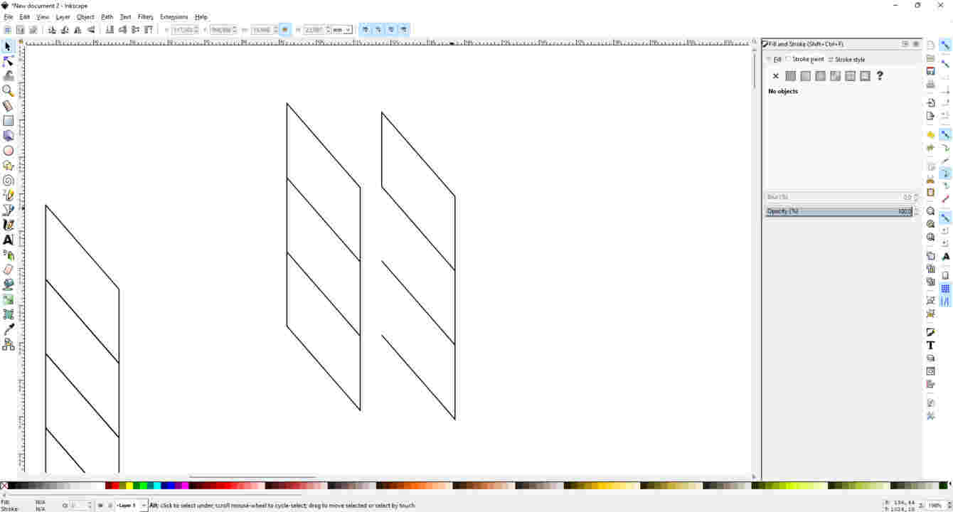
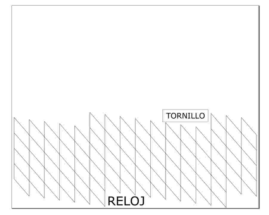
Our instructor said that if we just copy 2 figures one next to the other, we are going to see 5 lines (2 for height, 2 for lenght and 1 in the middle).
But the program will detect 6 lines, (2 for height, 2 for lenght and 2 in the middle).
And this was not a problem, but it was not a smart thing to do.
Because the machine will cut twice in the same part (the middle) as Inkscape will tell the machine that there, there are 2 lines. So the machine not only will cut a part that is already cut, but the lifetime of the cutter and the machine, will be reduced for no reason.
Due to this, we needed to do something about it.
We started to eliminate some lines, so when they will get attached in the program, the machine will not cut the same part twice.
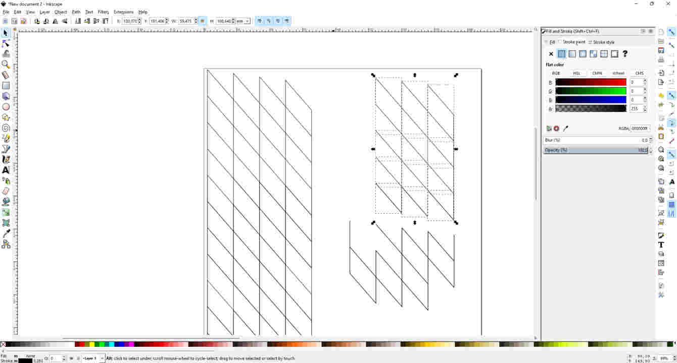
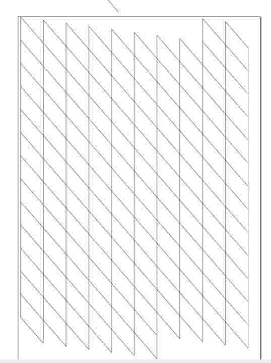
Now, for one reason that we don’t know, if we create a line between the figures, we can see that the figures are not straight, they have a slope.
| Every figure that I add next to the other is going down 2mm. |
|---|
 |
| After some editions and I ended up with these designs |
 |
 |
The printer that I used it was a CAMM1-Servo.
 My instructor first said that I need to read the manual to get the best information that I can. So before to use the Vinyl Cutter that is what I did.


After reading the manual I needed to see how much force the cutter will make. There is an option in the machine for it, very easy to test.
If the circle gets out with the square = too much force
If not the circle nor the square get out = too less force
If the circle gets out but not the square = the force is just fine.


As you can see from the image above, the best result of the test was with 180g/f
The machine has three option for loading the material.
1) Piece
2) Roll
3) Edge
You can find more information in the Manual Instruction
Usually we use “piece” option, and when loading correctly, the machine detects the size of the material and displays the values on the screen.
| see image below. |
|---|
 |
After getting the values, I change the page size accordingly in Inkscape, in order to do that we go to
File>>Document Properties.
 The final step in order to print the job we need to tell the driver to get the material size from the machine.
In order to do this we need to hit print or ctrl+p then select our machine Roland GX24 then click on Preferences
and click Get from Machine (see image below).
The final step in order to print the job we need to tell the driver to get the material size from the machine.
In order to do this we need to hit print or ctrl+p then select our machine Roland GX24 then click on Preferences
and click Get from Machine (see image below).

The result were a great success!
I thought that some of the stickers might look nice on my laptop

As well on the laser cutter machine

I grab a piece of blue sticker, for making the “caution area” for the laser cut machine.


2 Laser Cut
First what I did, was to calculate the thickness of the material that I wanted to cut.
In this case was a simple cardboard.
| The thickness of it was 4mm |
|---|
 |
After this I had to calculate the kerf.
2.1 Kerf
I had to create the “ruler” to calculate the KERF.
In simple words, the KERF is the additional material burned away when laser cutting.
| For doing this, I created a simple rectangle and started to modify the parameters. I created a parameter called “step increment” which reduced the size of every theeth in 0.05. |
|---|
 |
 |
Once everything was settled down, I went to coreldraw and started to copy the figures that I created on FreeCAD, with the precaution of deleting one line that connects so the laser won’t cut in the same place twice.

To print the comb, I just follow the rules and patterns of what I learnt in the group assignment giving this result:


I realised that the KERF was about 0.25mm.
2.1.2 Applying Kerf
Having this number (0.25mm) I started to re-design my figures, because the joint won’t be constrained as desired if I don’t change the value of it.
| I went back to my figures on FreeCAD and I applied a parameter called “Kerf” where I put it on the gap of the joints. |
|---|
 |
| Now I put it that value on the sketch. For this I need to “call” the parameter into the sketch. |
 |
Now my figures have the correct joint gap!
Having the correct joint gap will allow me to have perfect connections between the joints. Not too tight and not too loose.
Now I can print my figures without having any mistake on the dimension.
2.2 Printing
| After using FreeCAD to design my figures |
|---|
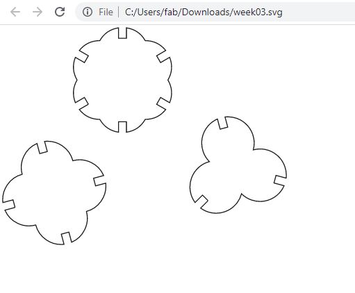 |
The next task was to print them.
For this, I will use the software CorelDraw, because for some reason, we can’t print to the lasercut using Inkscape. At the beginning a pop-up will appear asking you what dimension do you want to apply to your workbench.
As this machine is an Epilog-Laser Mini, the dimensions are in inches:
24in x 12in
I imported my figures to CorelDraw, and they got filled with black colour. To remove this, actually is very easy:
| I have the colours in my right side of the software, and I just clicked on the first colour that looks like an “x”, this is to empty the inside colours. |
|---|
 |
 |
 |
| After this I changed the border line of my figures, to “hairline”. |
|---|
 |
| And I started to copy and paste my figures in the workbench: |
|---|
 |
| Before printing you should be carefull and notice that the right parameters of the colours and lines are okay: |
|---|
 |
| When everything is good, I printed the my figures using the following steps: |
|---|
 |
Once I opened the preferences, I had to edit some parameters.
| This is a very important step: |
|---|
 |
Raster is used when you want to print with engraves.
Vector is used when you want to cut.
Combined is used when you want to do both.
As in this case I need to cut, I will used Vector.
I followed the group project assignment for the values of vector:

| Knowing the values, I ended up with something like this: |
|---|
 |
1 Is for the type of printing you want to do.
2 Is for the workbench dimension (24inx12in), but this depeneds on your machine.
3 Is for the values that you want to use for cutting certain materials.
After everything is set-up and cut, this is my result:


2.3 Tips for Corel Draw
-
- Alt + Q = Will make a text turn into a vector figure
-
- Pressing f10 and then right-clicking on the side a figure, will mark it and then you can press delete to delete that specific line.
-
- If you want to cut a specific line or a part of the line watch this video =D
3. Downloads
And these are my files:
Vinyl Cutter
Vinyl