2. Computer Aided design
- Babken Chugaszyian, my mentor, gave to the students an excellent presentation about CAD.
I don’t know anything about CAD, so I started to do my research:
1. Research
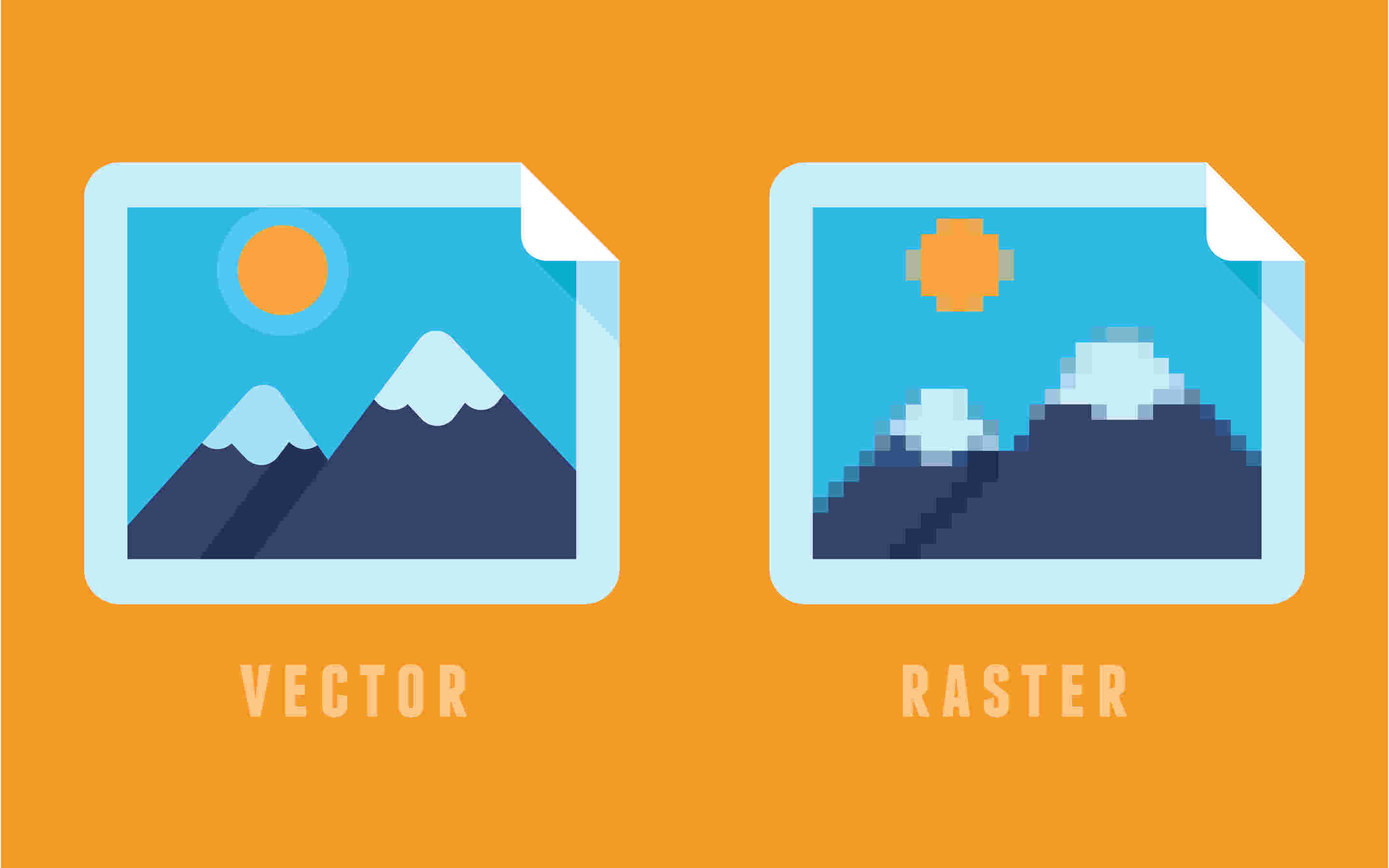
First, I wanted to know what does it mean “Raster graphic file”, to have a general idea of what am I going to work with.
(Source: SHUTTERSTUCK.com)
What I’ve found is basically that:
(Source: SIGNSOFSEATTLE.com)
-
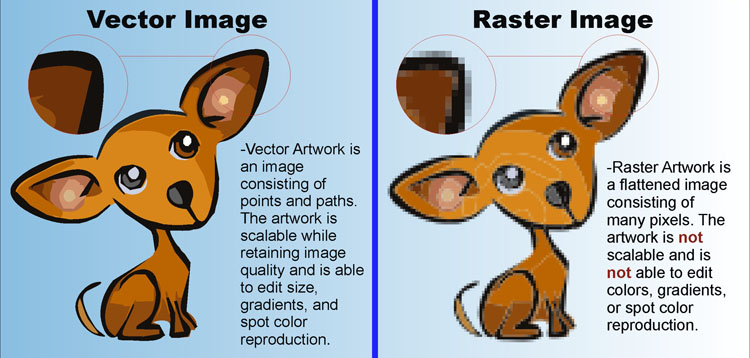
Raster (bitmap image) is used to alter non-line images, like digitalized photos, scanned art, or detailed illustrations or graphics. It consist in gradiatons and it is able to modify pixel by pixel.
-
Vector is used for design and illustration work, like logos. It uses mathematical equations, lines and curves with fixed points on a grid to produce an image. Because the mathematical formula recalibrates to any size, you can scale a vector image up or down without impacting its quality.
2. Softwares
I looked on the Internet about what are the bests CAD in the market on 2022:
2.1.1 Top Raster
The comparisson was made by the website WindowsReport. This top contains paid versions
- Adobe Photoshop: most popular raster graphics editor out there.
- Corel Painter: one of the most widely used raster graphics editor applications.
- Corel PaintShop Pro: is a top-rated raster graphics editor, which is specially designed for Windows computers. However, PaintShop Pro is not just a raster graphics editor, it is also a vector graphics editor.
- GIMP: is specially built to simplify the art of photo/image editing. It can be employed to retouch any type (format) of photos, and also change images from one format to another.
- Artweaver: it rounds up our list of best raster graphics editors. It is similar to Adobe Photoshop and Corel Painter in terms of functionality.
2.1.2 Top Vector
The comparison was made by the website Fixthepath. This top has only free Vector softwares
- Inkscape: vector program that provides advanced tools for working with shapes. You can also try cloning objects during operation, which will save your time.
- Vectornator: the unique features of this free vector program are advanced work with layers and the possibility to use an unlimited number of them to create the most complex illustrations.
- Vectr: This is one of the best free vector graphics software as it offers a large number of tutorials on managing layers, creating and editing paths, rotating and scaling objects, etc.
- Vecteezy: If you need a vector online editor that is free and very easy to use, then Vecteezy is what you need.
- Carbon: Carbon will be the best free vector graphics software for those who want to create clipart, logos, illustrations or photorealistic vector images. However, for these purposes, you can also use any Adobe Illustrator alternative too.
2.2. Using GIMP
First question when I opened GIMP “How do I use this?”.
I realised that GIMP works with layers, but still, nothing about a blank page to start my draws.
I was feeling that GIMP will requiere A LOT of time to learn it.
I gave up and I went to youtube to find a tutorial in Youtube, I will try to do something from this video.
So the first thing that I learnt was that for creating a blank space where I can work with, is that I have to go to “File”, and then click on “New…”.
And honestly, the setting that you can change from GIMP are a lot
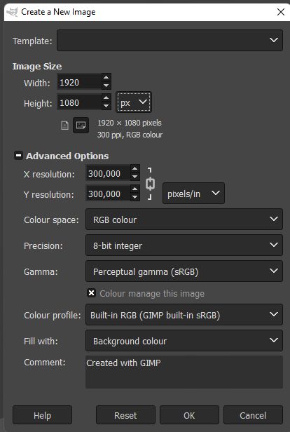
Just click “OK”. Now it’s moment to create the Layout
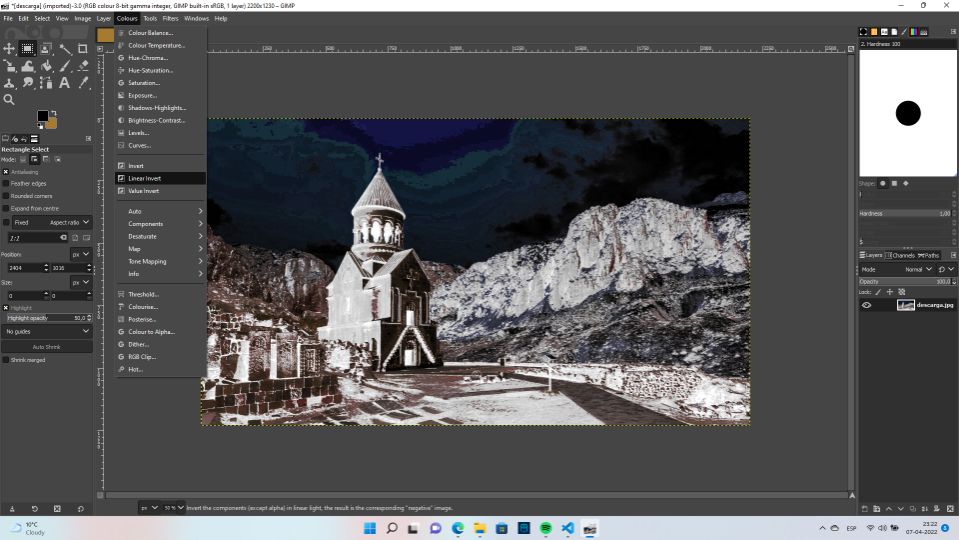
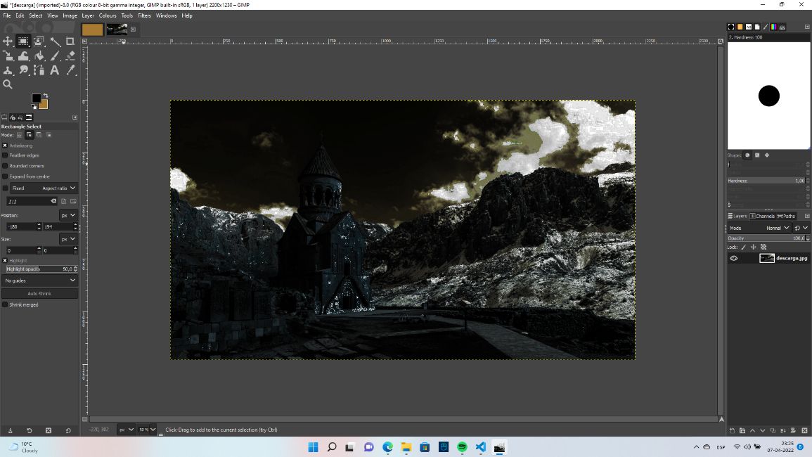
I’m going to try to edit and play with the picture of one of the old monasteries in Armenia.
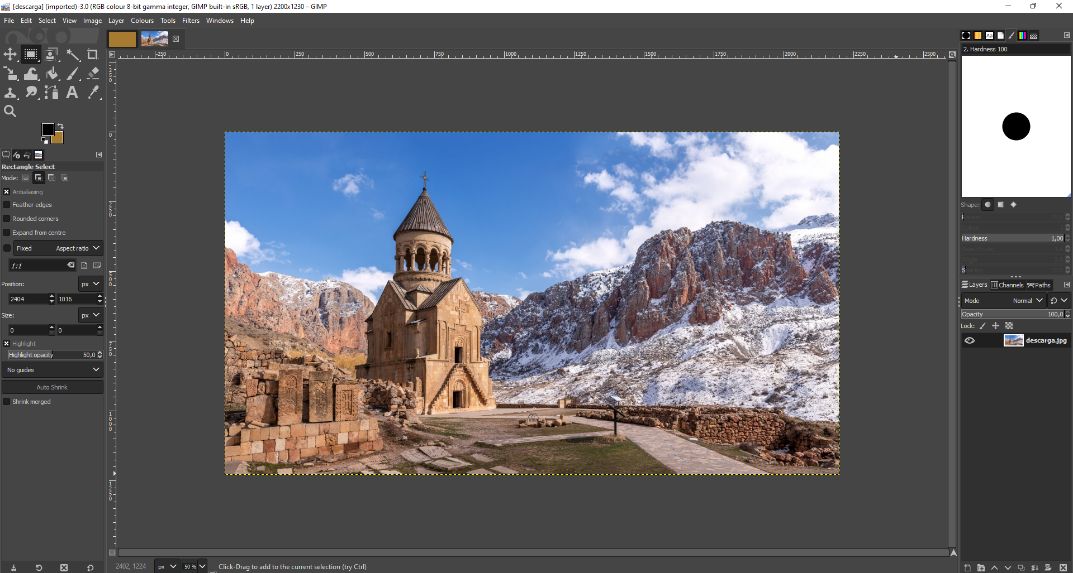
Playing a bit with the “Colour” toolbar, I turned the day into a night.
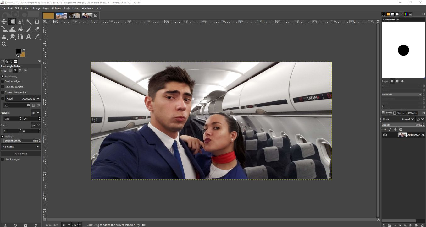
I don’t remember if I was here or not, but I’m going to try to be virtually.
For this, I opened another picture where I was with one of my old co-workers when I was a flight attendant.
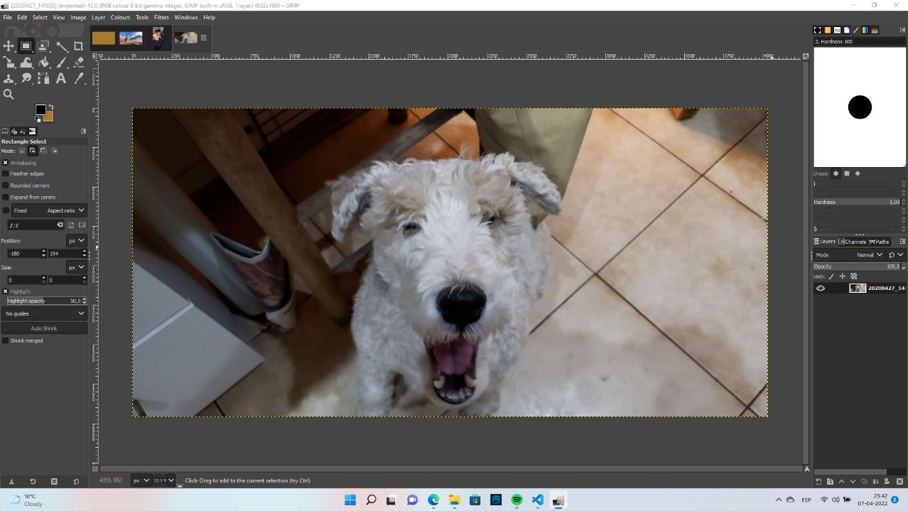
And as well I’m going to invite my dog “Kun” to this journey.
Sometimes, the “Fuzzy select” will not work that well. For this reason I would like to recommend an aplication made by Microsoft called Paint-3D
2.3. Inkscape
The first that using Inkscape I realised that it’s very intuitive and detailed about what you’re doing. I started putting random circles, and as soon as I started to draw. I saw vectors and no pixels. The circles can be deformed very well, with a variaty of options.
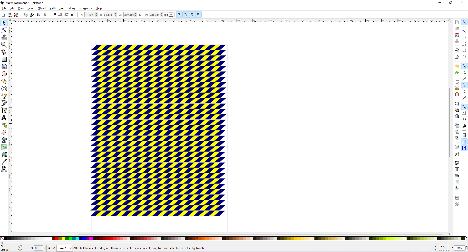
We wanted to put a tape in the floor for the laser cut machine, so the zone of it will be determined. For this reason we are going to use the software inkscape for working.
After choosing the colour and imitating the typical “danger zone” tapes, we finished the design with something like this:
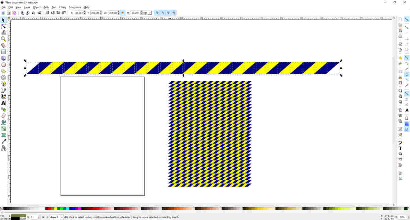
Once the image and design were ready, it was time to scale it to the size (large x wide).
We decided 3cm x 110cm As in Inkscape we worked with milimeters, we had to convert the unit of measurement.
When it was ready to print, an inconvenient happened.
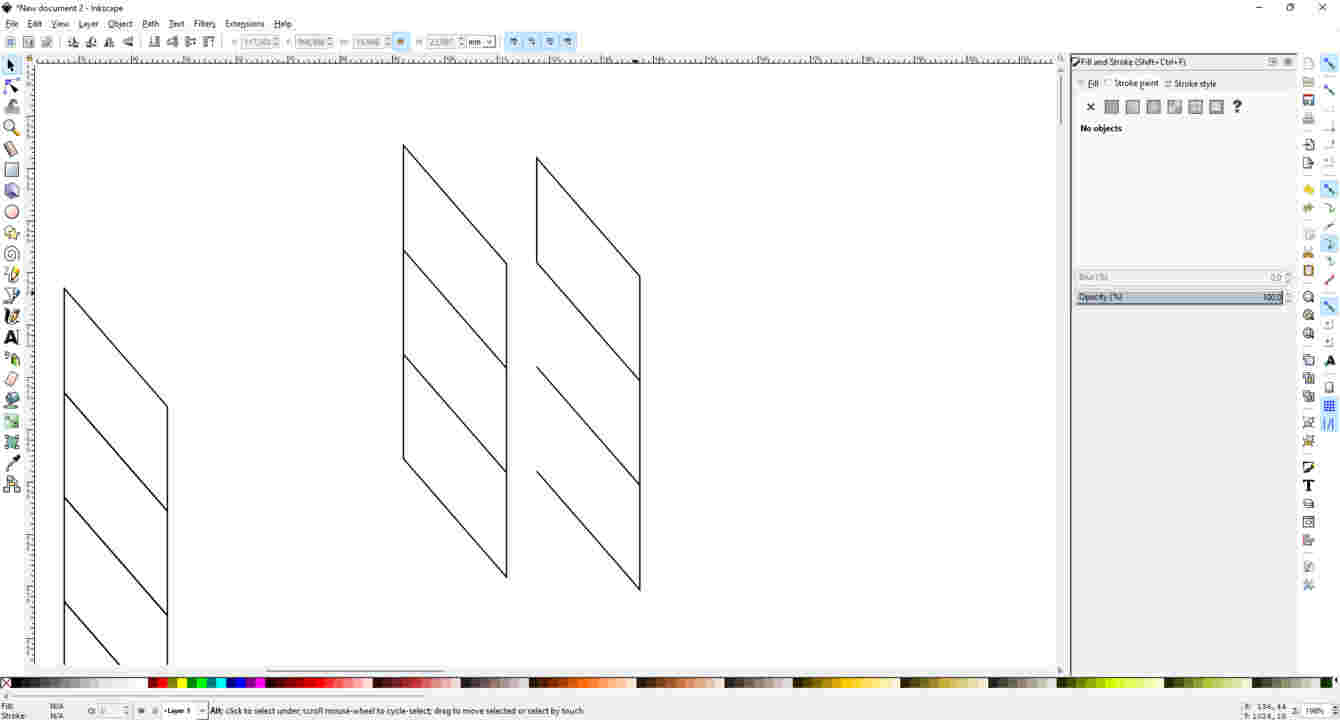
----> Our instructor said that if we just copy 2 figures one next to the other, we are going to see 5 lines (2 for height, 2 for lenght and 1 in the middle).
But the program will detect 6 lines, (2 for height, 2 for lenght and 2 in the middle). \ And this was not a problem, but it was not a smart thing to do. Because the machine will cut twice in the same part (the middle) as Inkscape will tell the machine that there, there are 2 lines. So the machine not only will cut a part that is already cut, but the lifetime of the cutter and the machine, will be reduced for no reason.\
Due to this, we needed to do something about it.
We started to eliminate some lines, so when they will get attached in the program, the machine will not cut the same part twice.
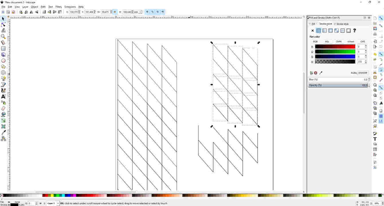
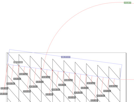
Now, for one reason that we don’t know, if we create a line between the figures, we can see that the figures are not straight, they have a slope. Every figure that I add next to the other is going down 2mm.
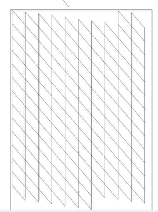
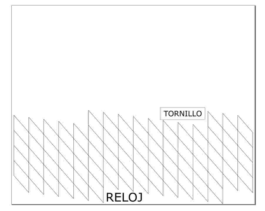
After some editions and I ended up with these designs
2.4 Blender
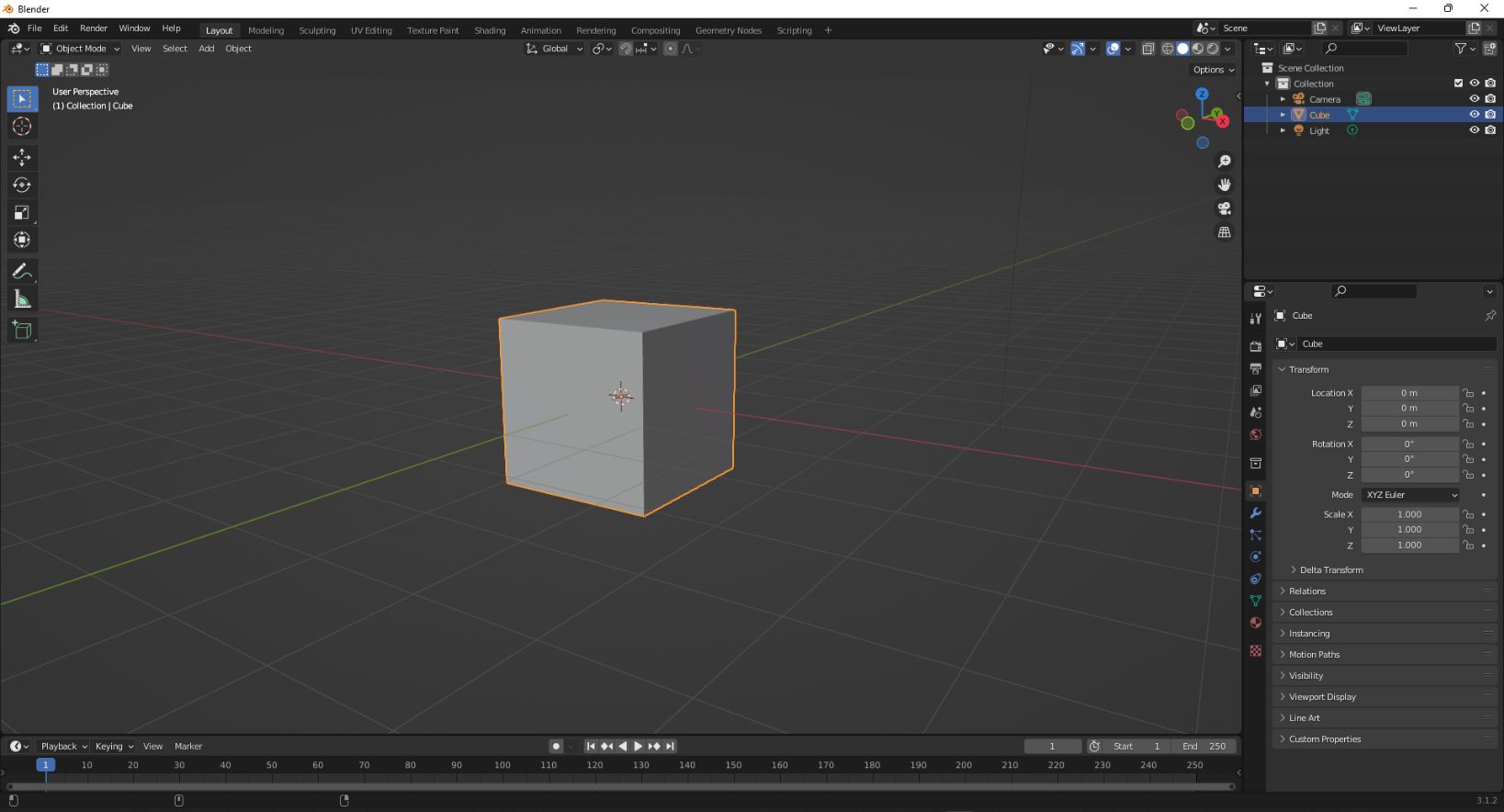
I chose Blender as it is a powerful open-source 3d software. For me it is a real new experience all this world, and I don’t have much talent on using this kind of programs.
At the beginning I could see a cube, I really didn’t know for what is this.
For this, I watched “Blender for nooobs”, a tutorial on Youtube
From the video I learnt that there are two most usefull short-keys:
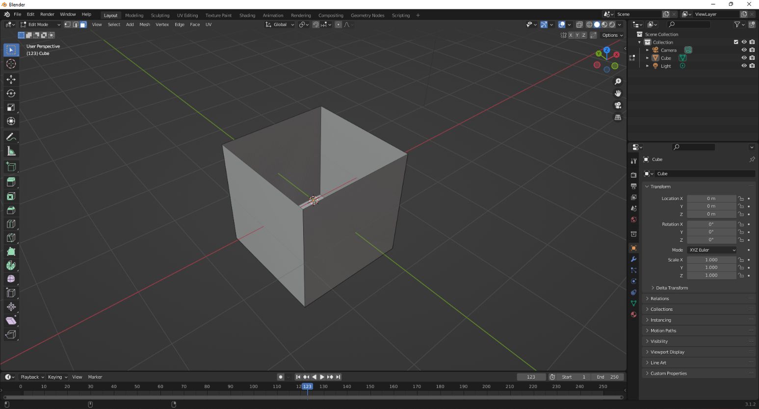
1. E : is for extrude.
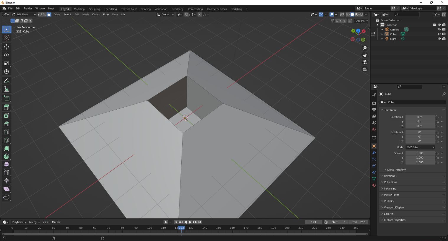
2. S : is for scale.
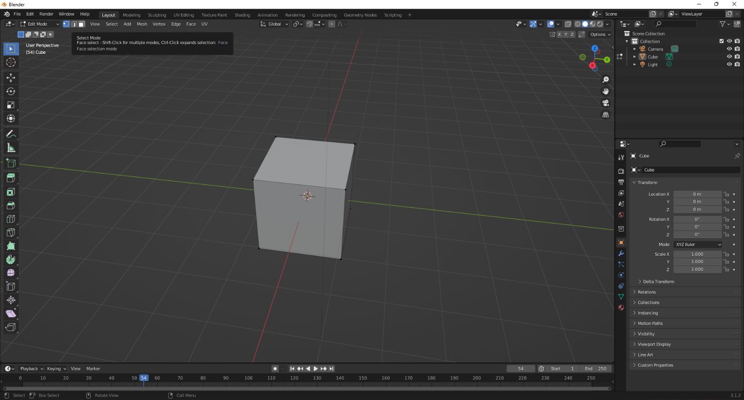
So pressing the “TAB” on the keyboard will open the “edit mode”
There are three different selections modes:
1. Vertex mode.
2. Line select mode.
3. Face select mode.
I’m going to use the Face select mode on this occasion.
Here you can see that I’m extruding this cube. The change that I did was to make a hole so now it looks kinda a box
Here you can see that I’m using the scale and I made sort of a “piramid shape”.
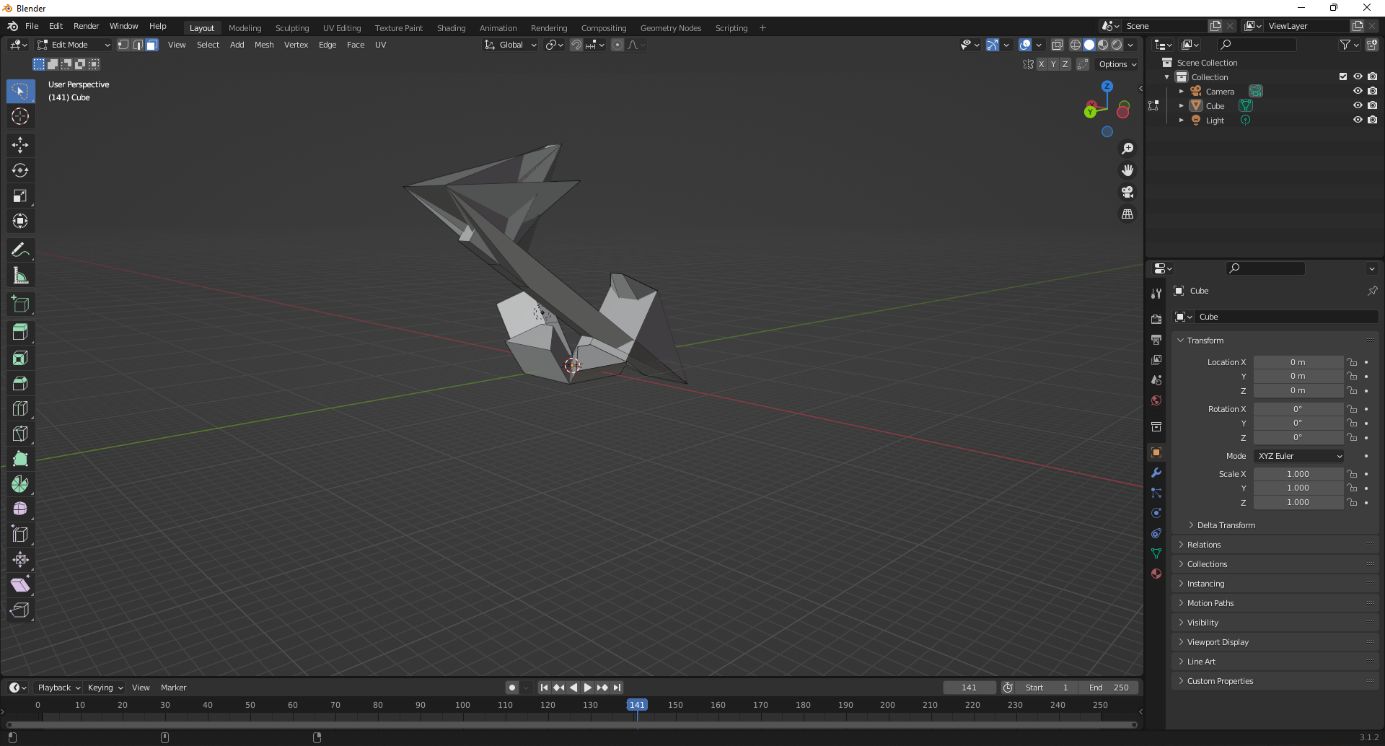
After playing a while it is fantastic how you can go from a simple cube to a figure that kinda looks like a statue.
3. Laser cut
After the tutorial of my instructor Babken in his workshop, I needed to do by myself.
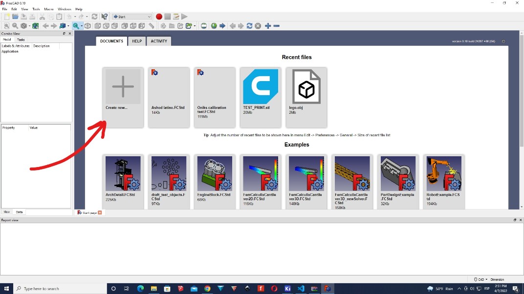
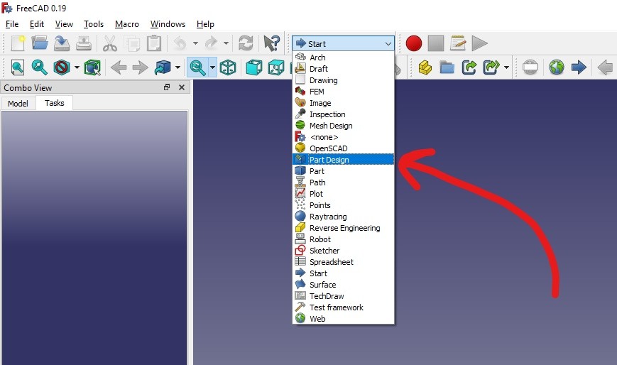
For this task I will use FreeCad
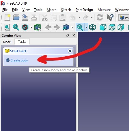
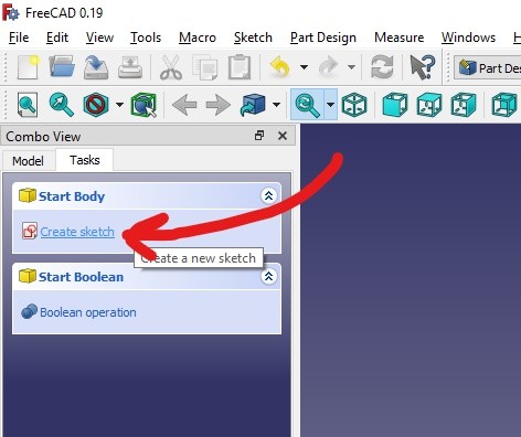
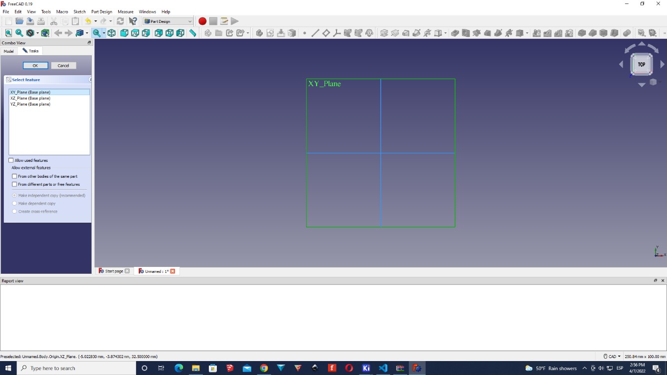
The first thing that I did was to click on “Create new…” and then I approach to the toolbar and select “Part Body”, and then I clicked on “Create body”. After this I selected “Create sketch” and then I select the plane “XY_Plane” and I clicked on “OK”.
     |
|---|
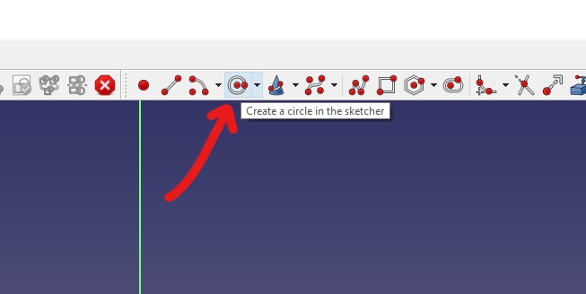
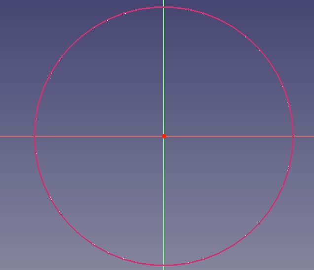
Now I have two axes, so what I did was to create a circle as a guide.
For this I selected the option “Create a circle in the sketcher” in the toolbar and I put it just right in the middle of the plane. And then just click and create a circle.
  |
|---|
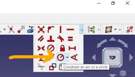
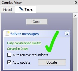
After this, to make your circle parametric, you need to go to the toolbar and select “Constrain an arc or a circle”.
In my case it wasn’t showing, so in my case I had to first, click on the “>>” symbol.
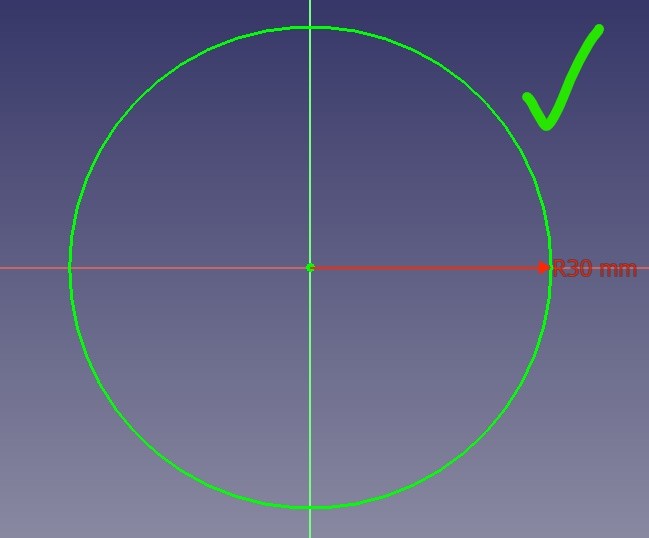
Then I clicked on the edge of the circle (where the red border is), and it will turn yellow. And then I put a number that it was reasonable.
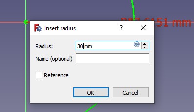
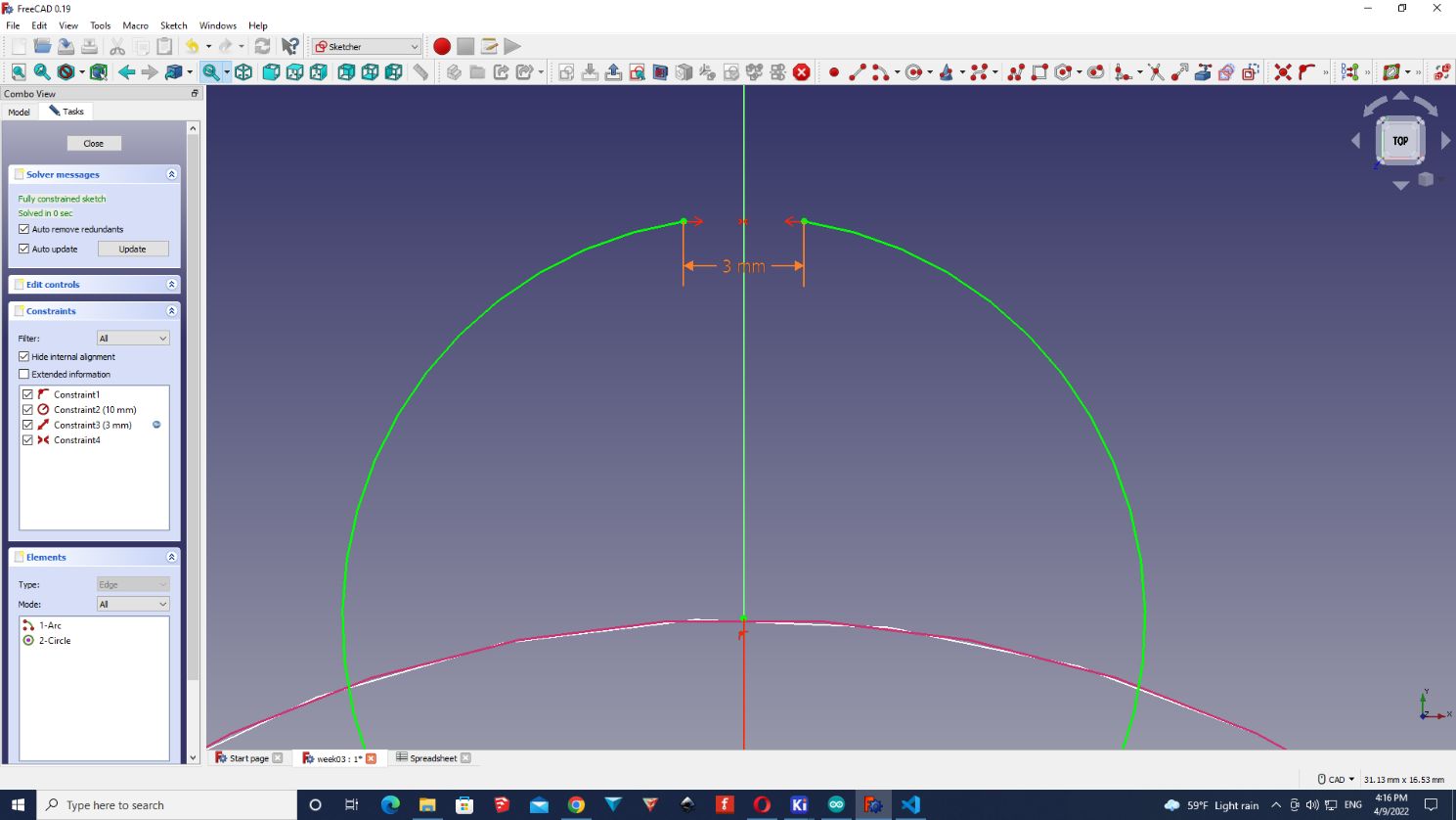
In the menu of the left, you can see a box called “Fully constrained sketch. Solved in 0 sec”. This means that the figure won’t move, or change. And this is a good thing for FreeCAD.
  |
|---|
So far we are playing with colours.
| Main Colours of FreeCAD |
|---|
| Red: When the sketch is not constrained (you can move it, change it). |
| Yellow: When you can select a line, arc or dot in the “Sketcher”. |
| Green: When the sketch is fully constrained (you can’t modify the figure). |
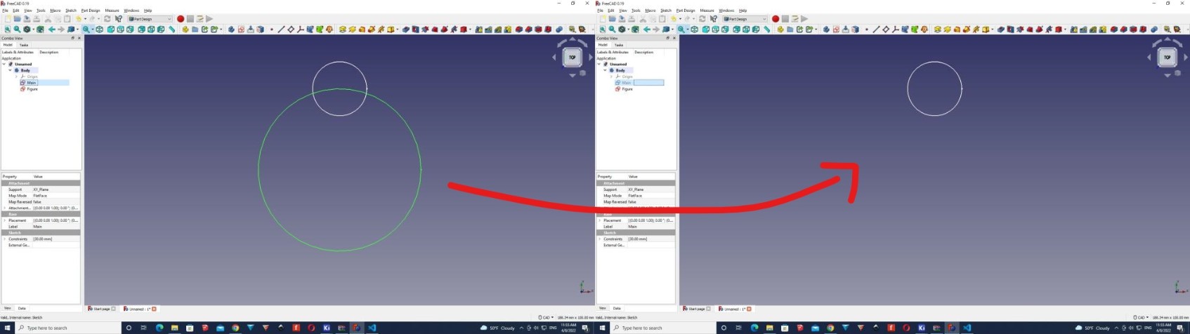
Now that we have our main circle, or our guideline, I’m going to start designing my parametric figures.
For this, I will create a new sketch using the same plane (X,Y).
I’m going to follow the same steps than before, but this time I’m going to use this usefull tool that doesn’t have a name, but it is detailed as “Create an edge linked to an external geometry (x)”

Note
According to the FreeCAD website it is called “Sketcher External” and it’s used when you need to apply a constraint between sketch geometry and something outside of the sketch.
Using this tool allows me, to work with a previous sketch as a reference without making any change on it.
So you can see how it paints the sketch that I want to make as reference like a dark red colour.
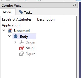
It is a good idea to change the name of your sketches, or bodies, so you will be organized and you won’t loose time searching for a design that you want.
 |
|---|
Pressing the key “space” will dissapear/appear the sketch that you want.
I’m pressing “space to dissapear the “Main” sketch, so I can work with the “Figure” sketch freely.
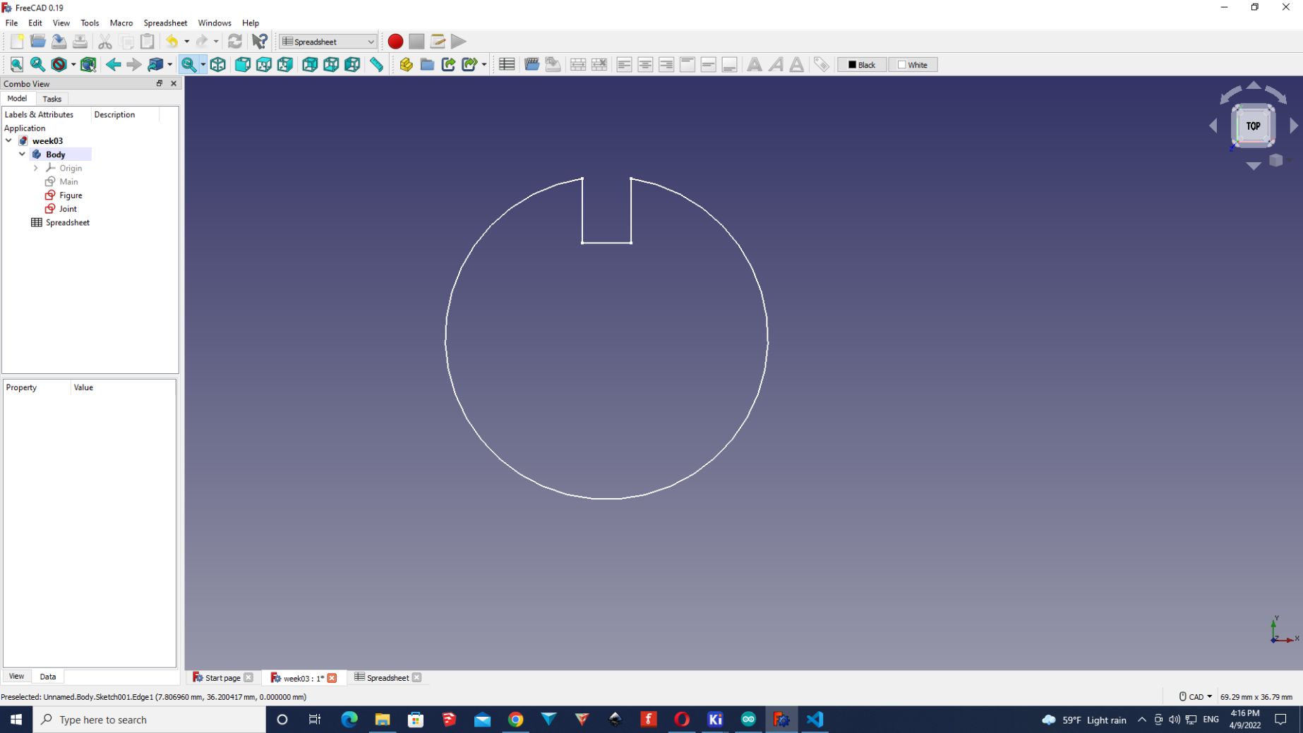
As the design that I’m doing now it will be the design that I’m going to cut in the next week, I will create joints. About the size I decided to make it 4mm x 4mm.
So I used the same method as before
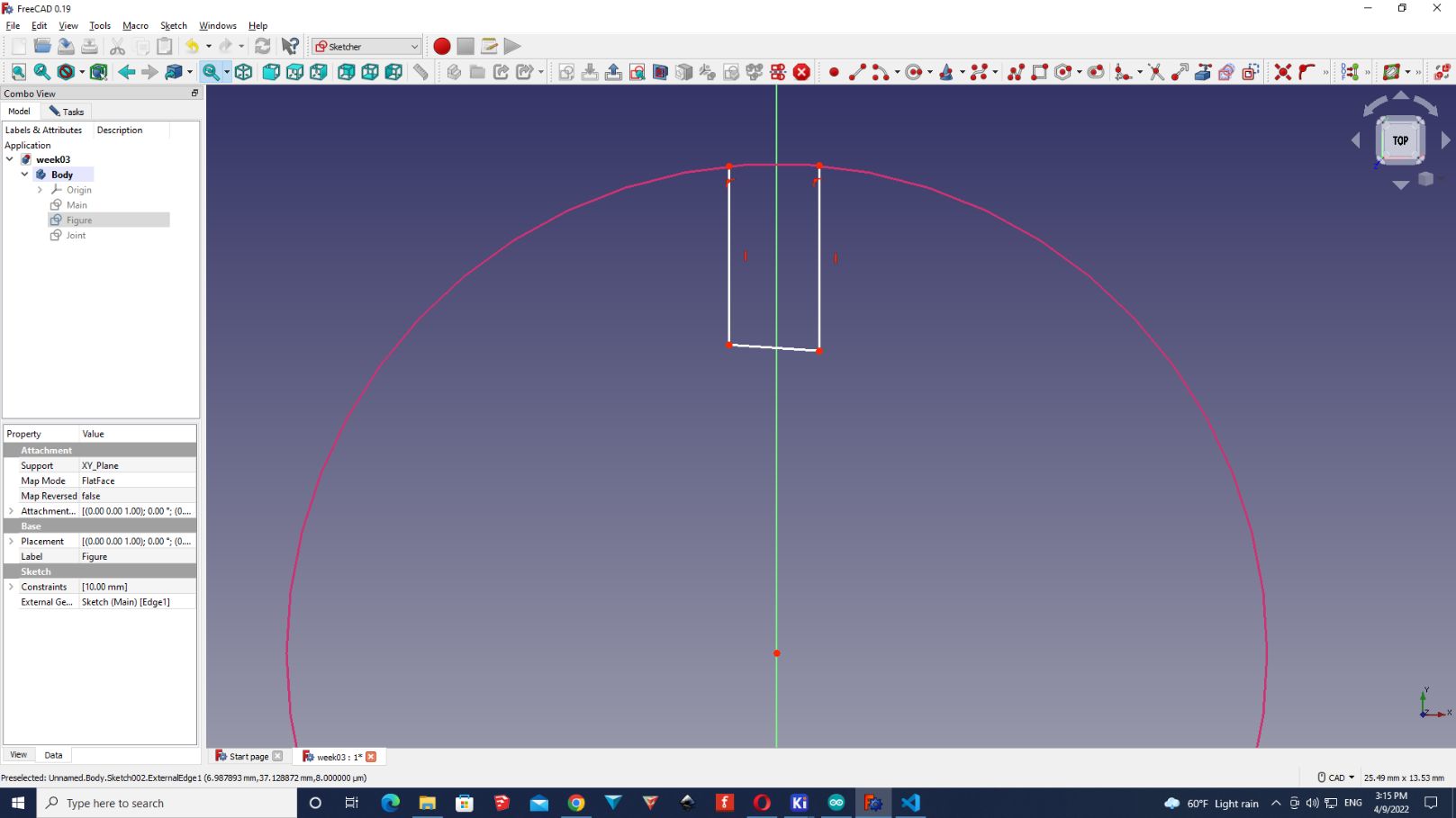
Now, as you can see , the joint it’s a little bit ugly. The reason is, because is not parametric.
So for making it parametric, we will need to use the “Spreadsheet” tool.
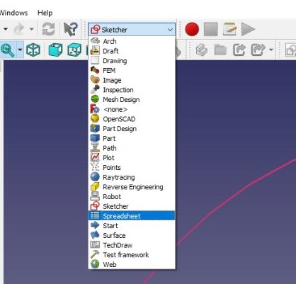
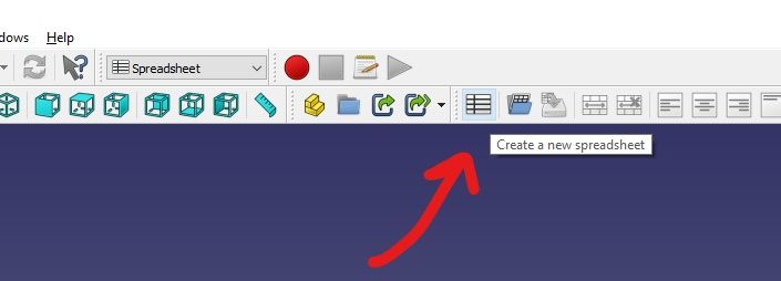
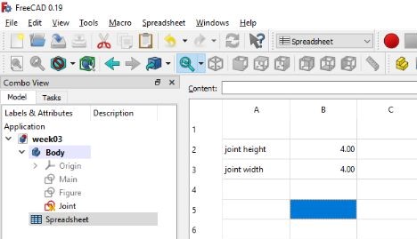
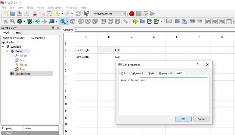
I put some values to the joints, but this doesn’t mean that they are parametric. For doing this I will have to right-click on the number, properties and then, click on “Alias”, this will allow me to “call” the parameter when working with the lines.
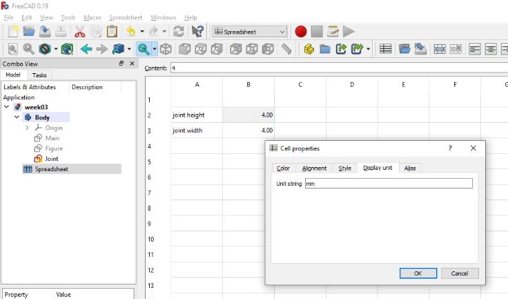
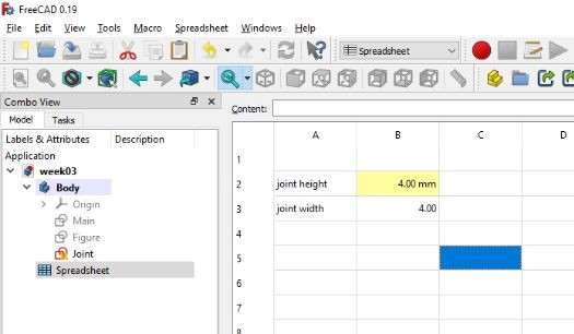
As well, click on “Display unit” and write the unit that you are working with. For my case it’s in mm.
You can see how this number is painted yellow, this means that is a parameter now.
Next, when you go to the sketch of the joint, I clicked on one line of the joint and made the shortcut shift+D. This will open the “Insert Lenght” option. Click on this icon and then write
Spreadsheet.
followed by the parameter that you want to “call”.
For example:
Spreadsheet.jointy
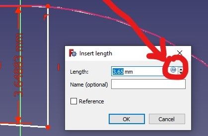
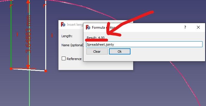
It will automatically assign the value that you set before.
Now I did the same with the other lines and I used two very handy tools that can be helpfull.
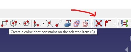
If you want to attach two points in one use this tool.
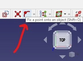
If you want to attach a curve into a line use this tool.
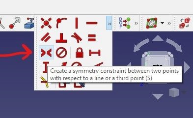
If you want to make a symetry (equal distance) between two points use this tool.
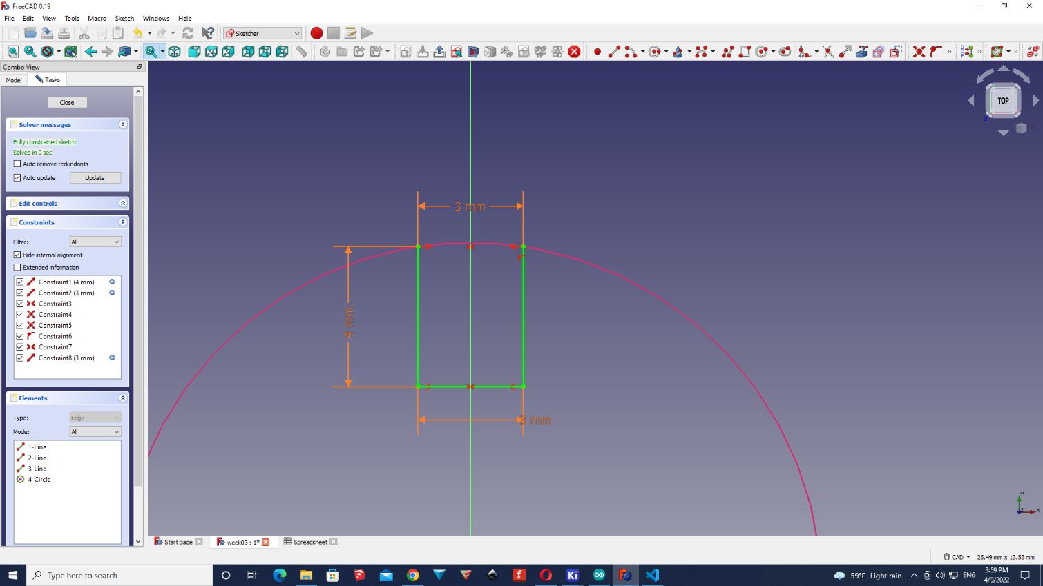
And after some fixes, my joint is fully constrained and parametric.
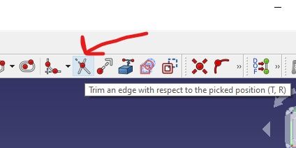
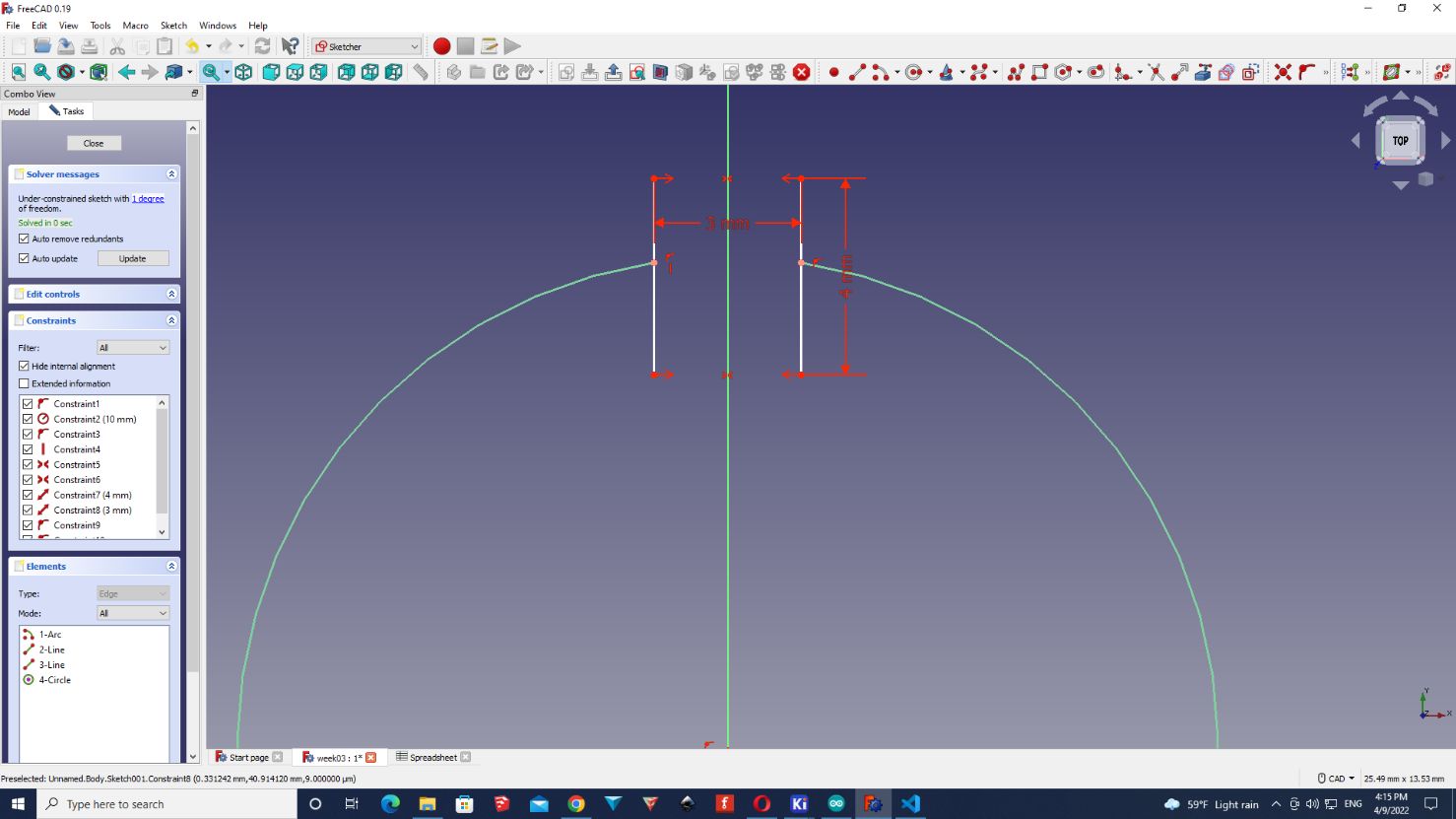
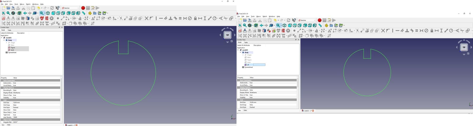
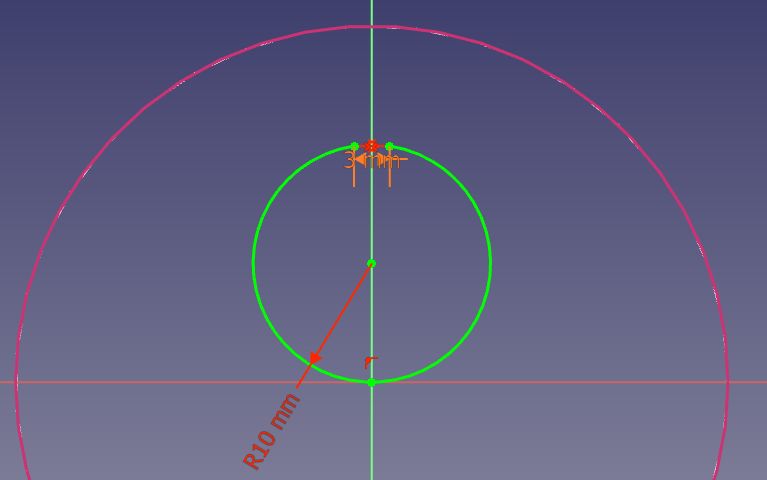
Now, one problem that I’m facing is that the circle is blocking the entrance of the joint, for this reason I used this tool to cut the arc between the joints.
One problem that I had is that as the joint and the circle don’t belong to the same sketch, so I had to simply create two lines symetry with the y-axis, with distance of 3mm in the sketch of the circle. The rest was easier.
Whenever I tried to PAD my figure, as I had two “open” sketches, this error always jumped.
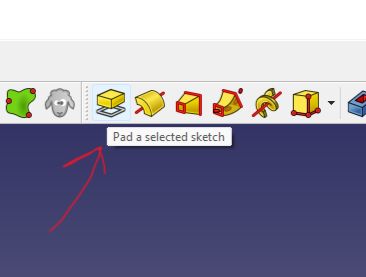
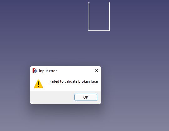
So what I had to do, was to put both sketches in one.
For this, I went to the “sketcher” menu, and I selected both sketches. After this, I clicked on this icon.
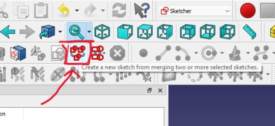
And I ended up with a 3D model in FreeCAD
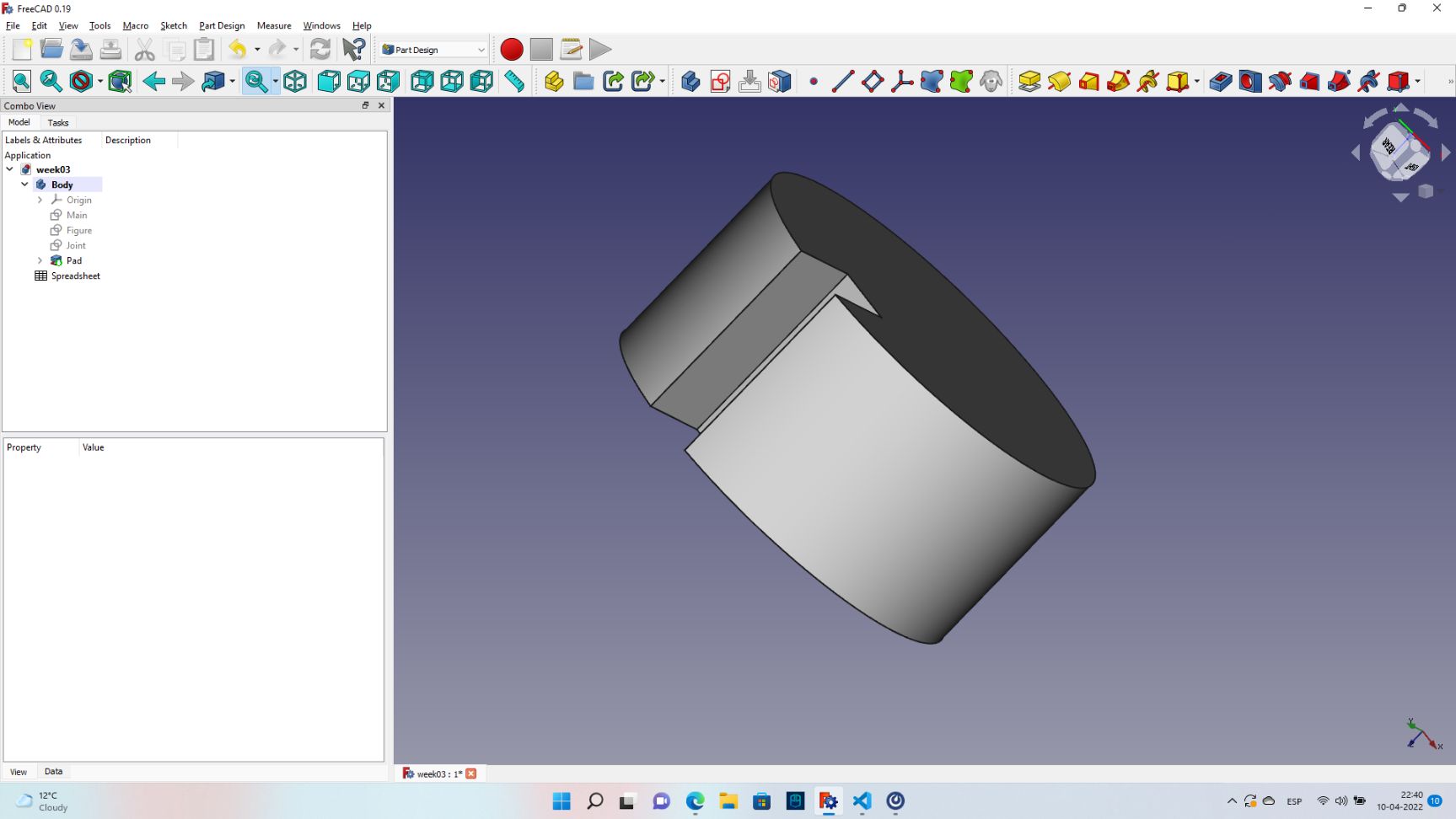
I will continue working on this, because I will need to use the laser cut machine for cutting this figure.
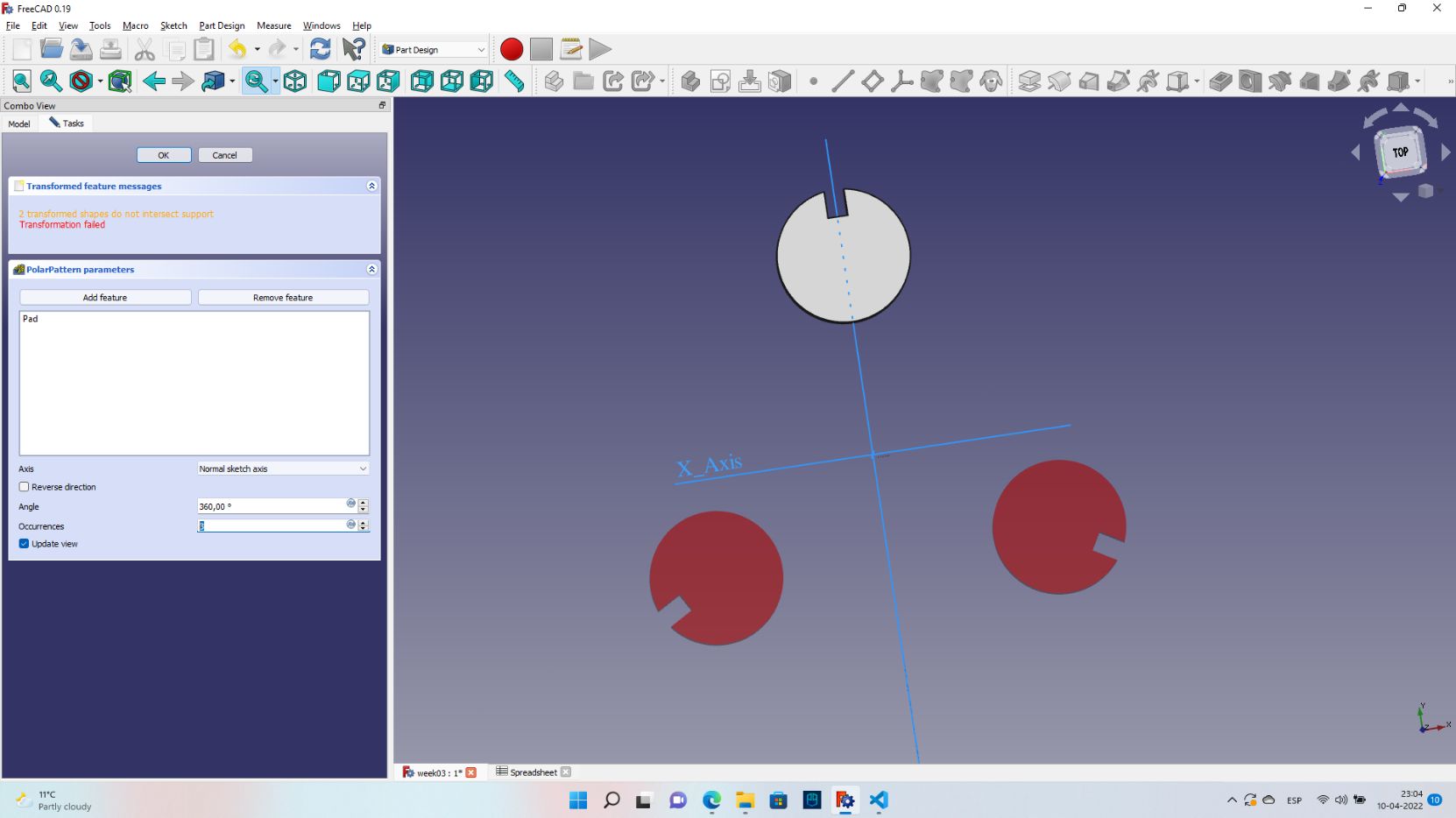
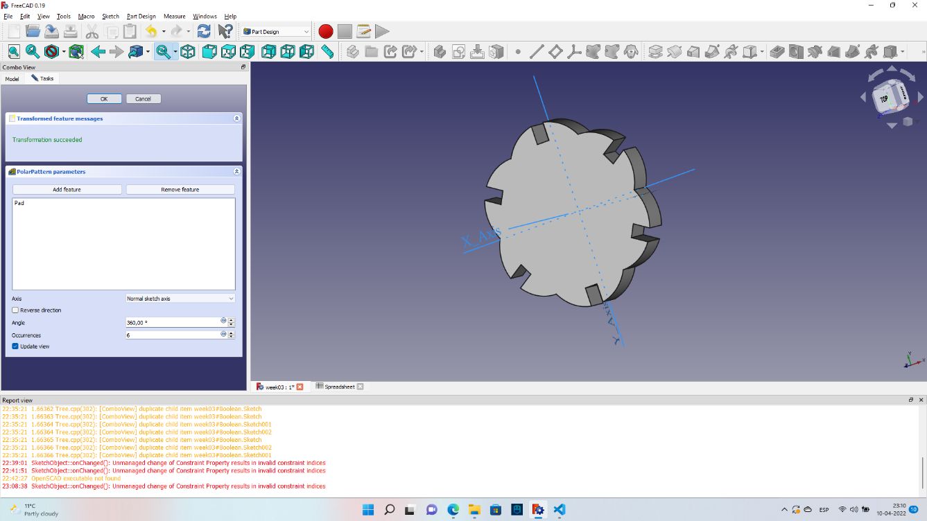
So I will start using the tool “Polar Pattern” to generate joints.
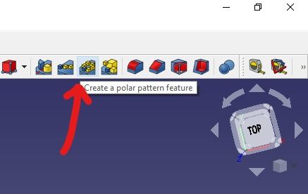
One error that I found, is that if the figures that I’m adding don’t touch one with each other, it will be impossible for them to generate another figure. so it would be good if I work in the center of the sketch (0,0), because the angle there it will be less.
Now it looks nice!
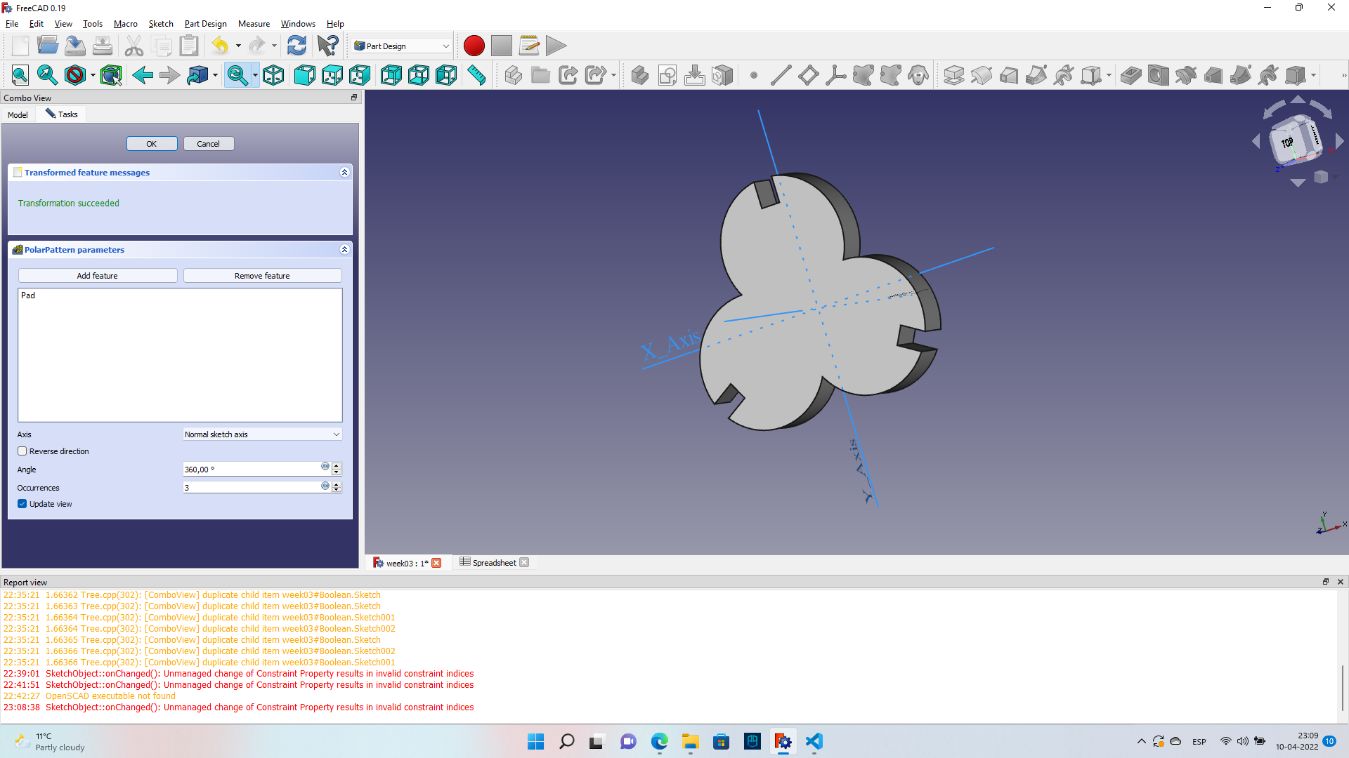
I can even increase the number of conections.
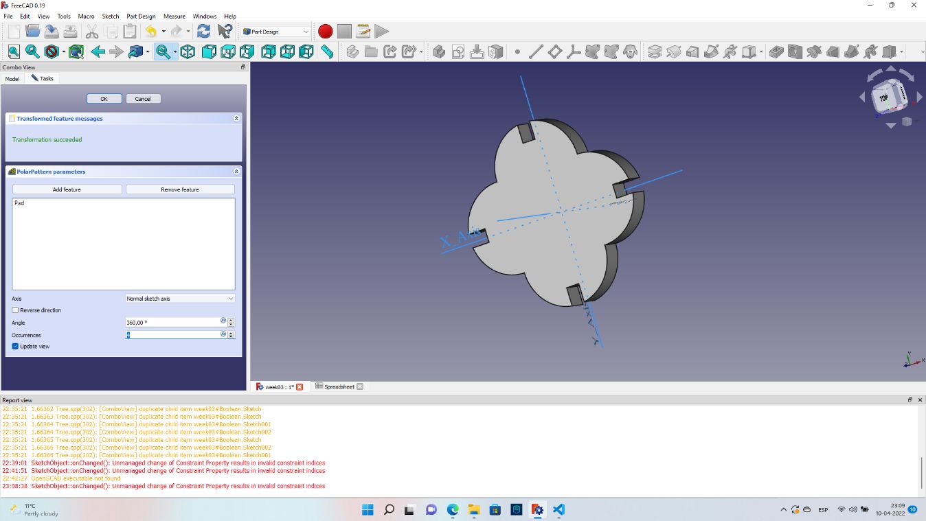
Now that I have a body and I have my spreadsheet, I can start making copies.
For this, in the workbench (menu) of “part” I need to go to the toolbar in the top and click on:
Part>>Create a copy>>Create a simple copy
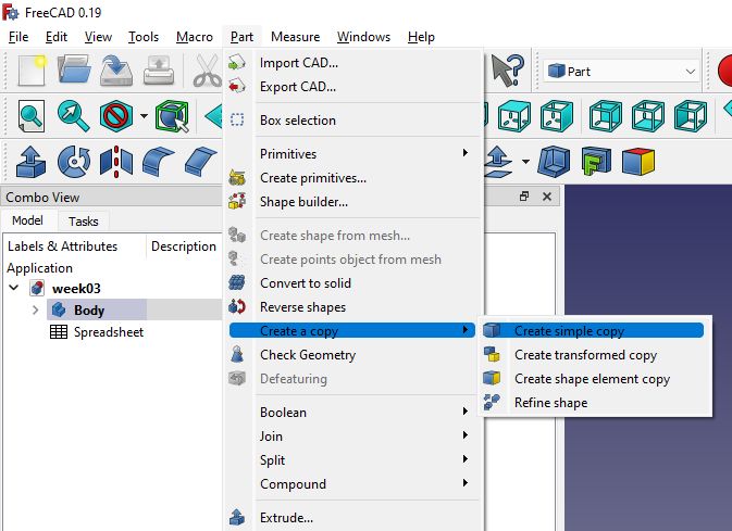
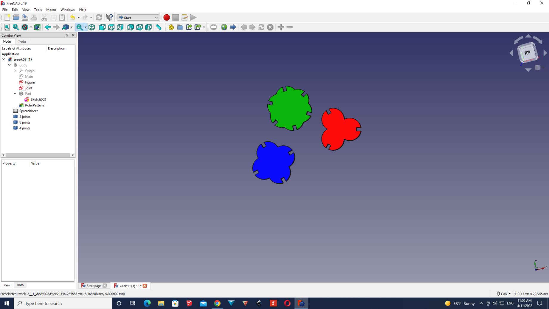
So with this I can save the figures with different joint numbers.
I even change the colour of them to differentiate them better.
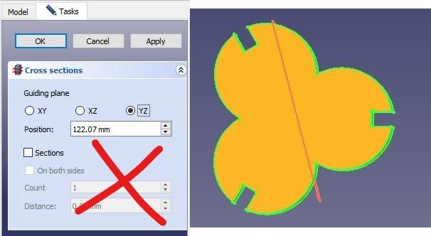
Now, we are going to use the tool “Cross-sections”, if I click it, it will show me the planes where I want to cut it.
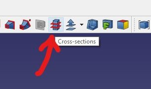
Obviously, I’m going to select the “Guilding plane” of XY. And then I hit apply.
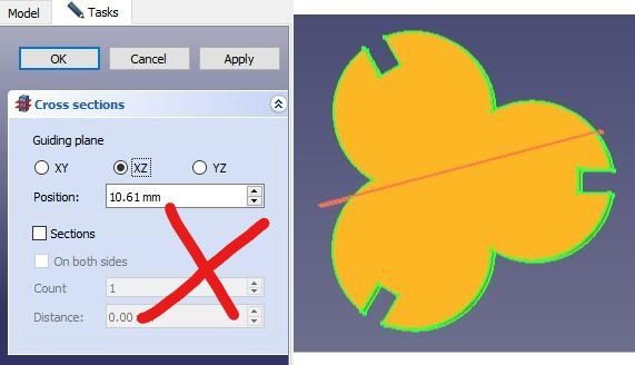
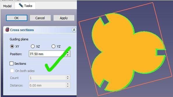
At this point, there is no such a difference, but if I hide my 3D model by hitting “space bar” on the keyboard, I will have my 2D model of my figure.
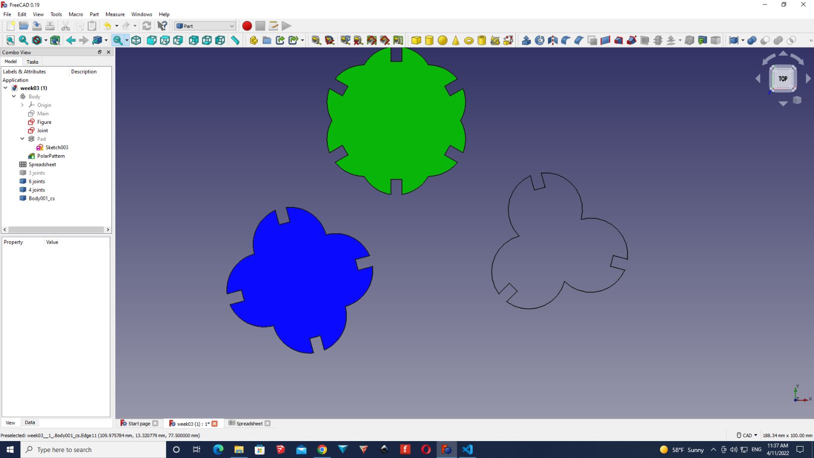
I will do the same for the other two figures.
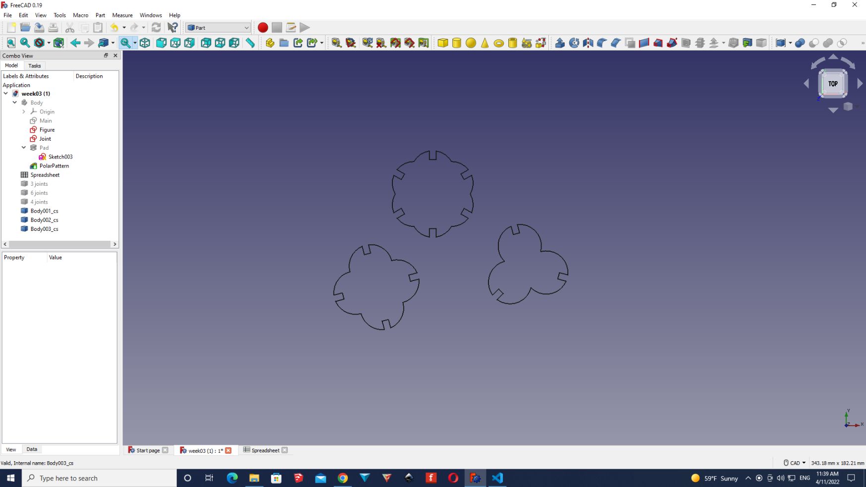
Now for exporting this files, I can select them all and click on
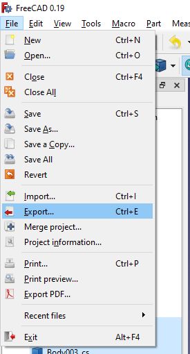
File>>export
And select [.dxf] or [.svg].
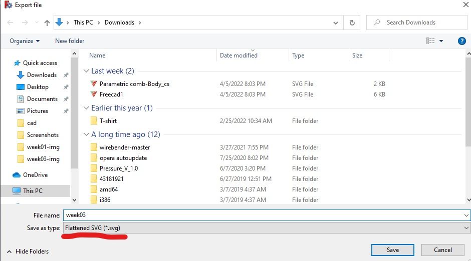
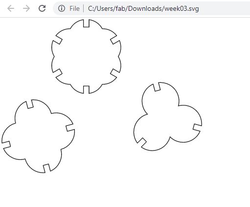
I will select .svg, and as you can see my files have a clean shape, that I can re-draw it or laser cut it.
3. Downloads
[Inkscape]
.SVG