11. Input Devices
Group assignment page:
If you want to check out our group assignment page, check this link
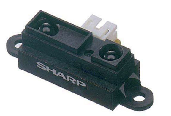
For this week, I wanted to use a distance measuring sensor unit.
Specifically the Sharp GP2Y0A21.
Measuring distance: 10 to 80 cm
Analog output type.
This sensor will allow me to complete my final project as I want it to be a touch-less instrument, that you can play without strings. Like a theremin.
I found a very good explanation about Input/Output Interfacing, it’s in PDF and you can download it from this link
By “simple” digital input we mean input from switches or other devices that produce a few bits to indicate their state. For example, a car electronic managment system may wish to monitor 10 switches indicating whether 5 seats are occupied and 5 seat-belts buckled; or a chemical plant might wish to report whether valves are shut or not.
In input devices what it matters is the “Physical world”, whatever stimulus from the real world, it will convert the stimulus into data, and the microcontroler will read the data and export it to the Output device (if you have one).
From the website Components101, for example, it explains about “What is an ADC (Analog to Digital Converter)?”:
An analog to digital converter is a circuit that converts a continuous voltage value (analog) to a binary value (digital) that can be understood by a digital device which could then be used for digital computation. These ADC circuits can be found as an individual ADC ICs by themselves or embedded into a microcontroller. They’re called ADCs for short.
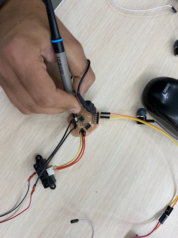
Probe Analog Signal
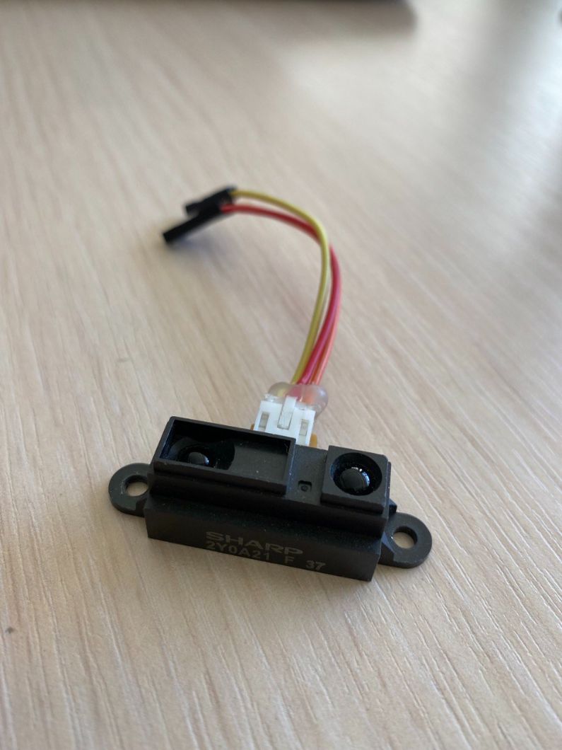
For the analog signal we used a Sharp Distance Sensor - gp2y0a21.
| We connected this distance sensor to an Arduino: |
|---|
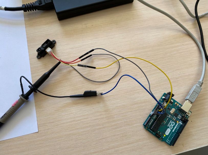 |
| The way we connected to the Arduino was using simply the data sheet of the distance sensor |
| You can find the data sheet and everything in the top of this “Probe |
| For making easy to understand |
|---|
| These colours are from the Distance Sensor |
| Yellow cable -> VCC (connected to Arduino) |
| Red cable -> GND (connected to Arduino) |
| Orange cable -> Vo (Connected to Oscilloscope) |
| We connected as well the Oscilloscope to the GND of Arduino |
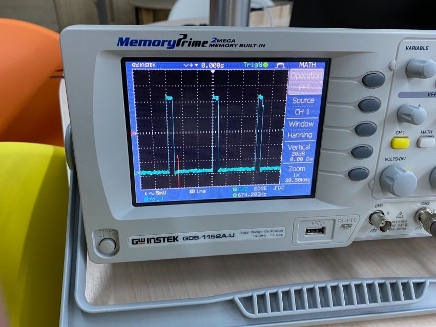
| This is the Oscilloscope that we used |
|---|
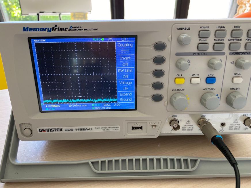 |
| And this is how the oscilloscope was getting the “information” from the Distance sensor |
|---|
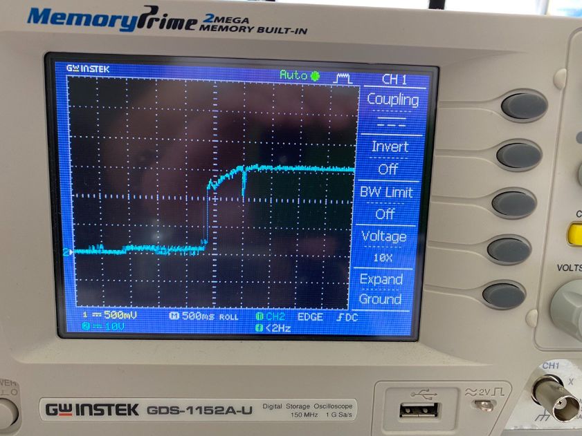 |
| Here what is showing us, is that the distance sensor has a fluctuation of 3V as the output voltage |
| You can see it better in the video below |
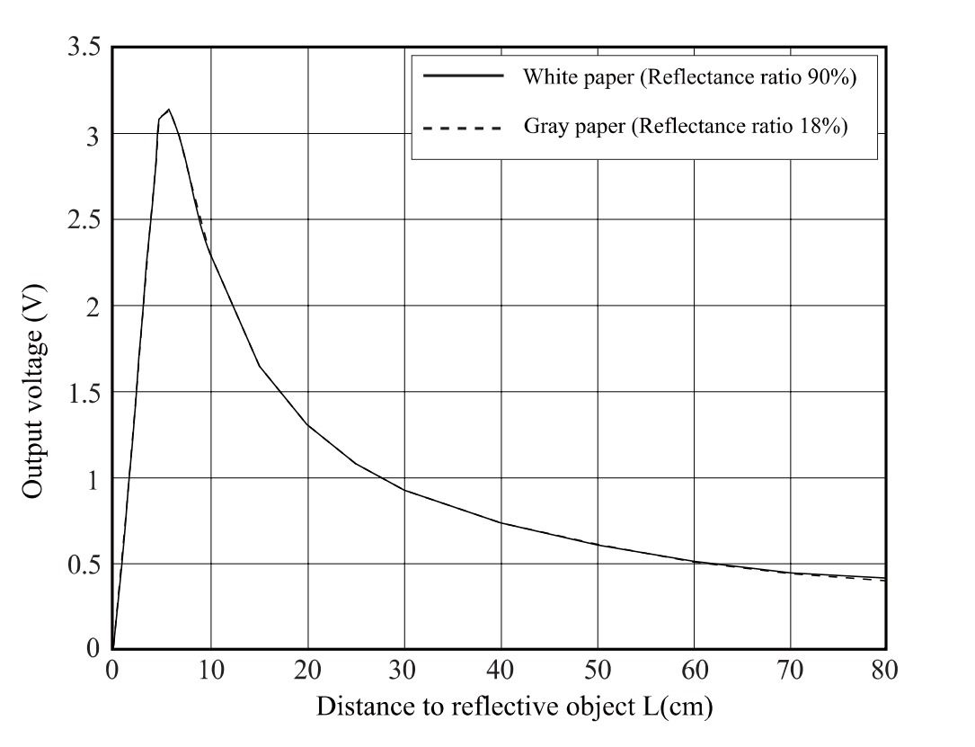
Which is absolutely incredible, because if we go to the data sheet of the distance sensor, in the page number 5, it shows exactly the measuring characteristic as we detected using the oscilloscope
| Here you can see the “Distance to reflective object” |
|---|
 |
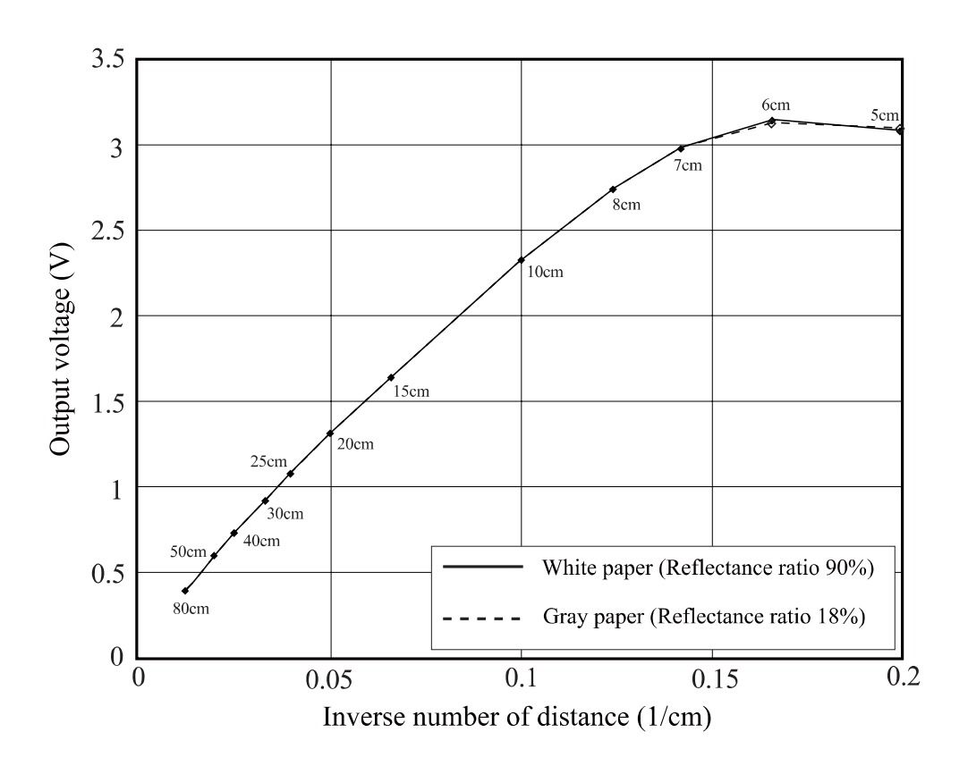
| And for more detailed characteristic, here is the “Inverse number of distace” |
|---|
 |
Probe Digital Signal
For this one, I looked in Youtube about the “Digital Read” with a button, and I found a quite good video! It practically shows everything about using a button (digital read) with a very simple code. Basically, it read a serie of “zeros” (0000000000) and “ones”(111111) when the button is pressed.
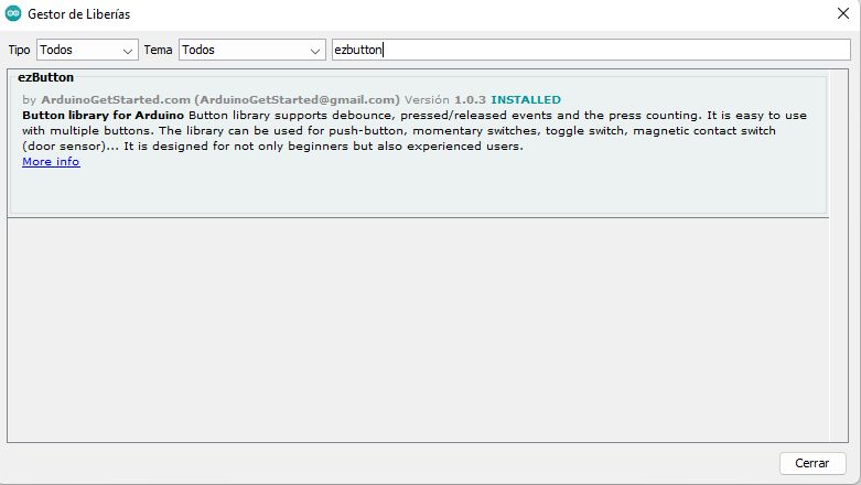
In my case I used Arduino IDE and I found a very good Library, it’s called “ezButton” and what it does it simply make it easy the programming using button. Very easy to use and understand!
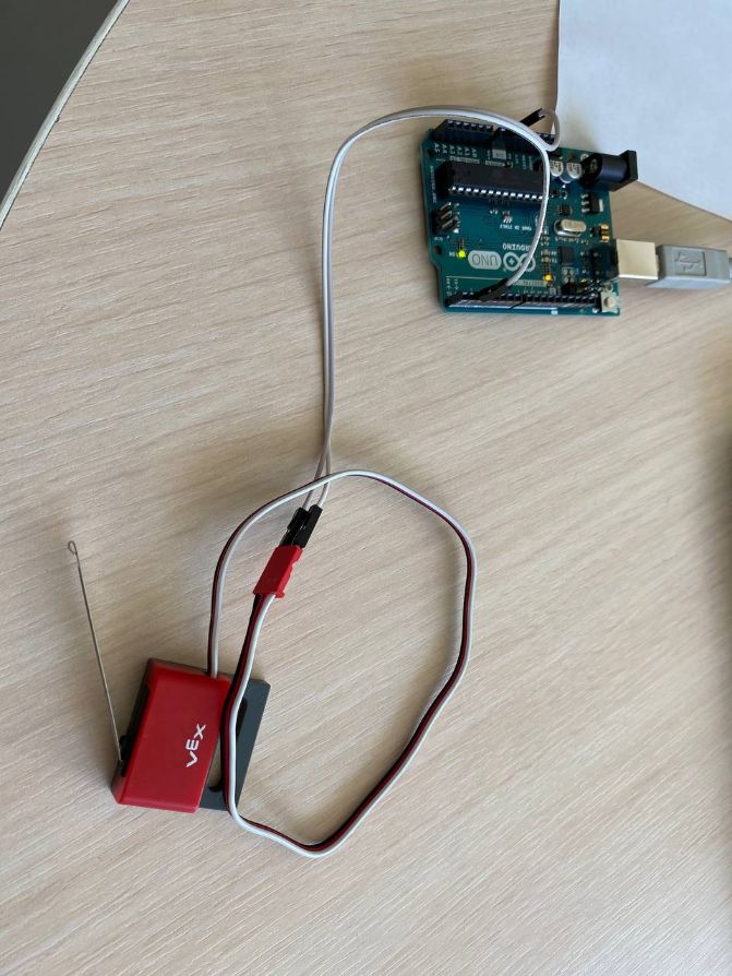
So what we did was to connect the button “Vex Limit Switch-4462AA to the Arduino.
This is what I found in the data sheet:
3-Wire Cable
Connect to a digital input:
Black: Ground
Red: No Connect
White: Control signal
As it didn’t have “VCC” I connected the white cable to the pin°2 and the black to GND.
After this I found this good code, I just simply change the pin°7 no the pin°2 that I was using, and the outpu that it will read in the monitor.
#include <ezButton.h>

ezButton button(2);  // create Button object that attach to pin 2;

void setup() {
  Serial.begin(9600);
  button.setDebounceTime(100); // set debounce time to 100 milliseconds
}

void loop() {
  button.loop(); // MUST call the loop() function first

  if(button.isPressed())
    Serial.println("Bab");

  if(button.isReleased())
    Serial.println("kiño");
}
In this video you can see it in action:
Now I had a bit of ccuriosity and, instead of “Babkiño”, I tried to use the “zero”(0) and “one”(1) as in the first video. After changing the code, instead opening the serial monitor, I opened the “Serial Ploter”.
And this is what I have:
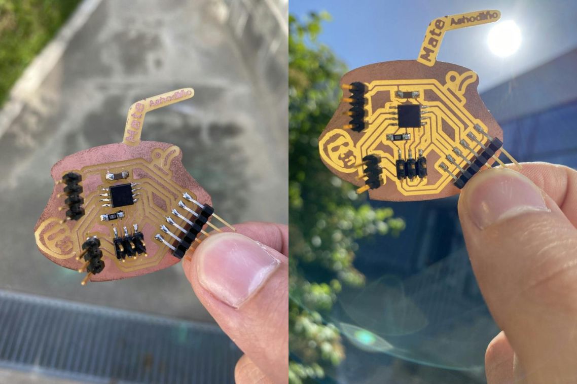
Creation of the PCB:
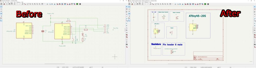
After weeks of training and development in my skills of making schematics, I finally could advance in a next level of designing in KiCAD.
You can clearly see my progress in this comparisson, I’m very proud about it:
 |
|---|
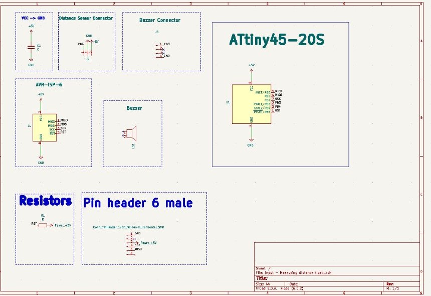
The details of my PCB are here:
 |
|---|
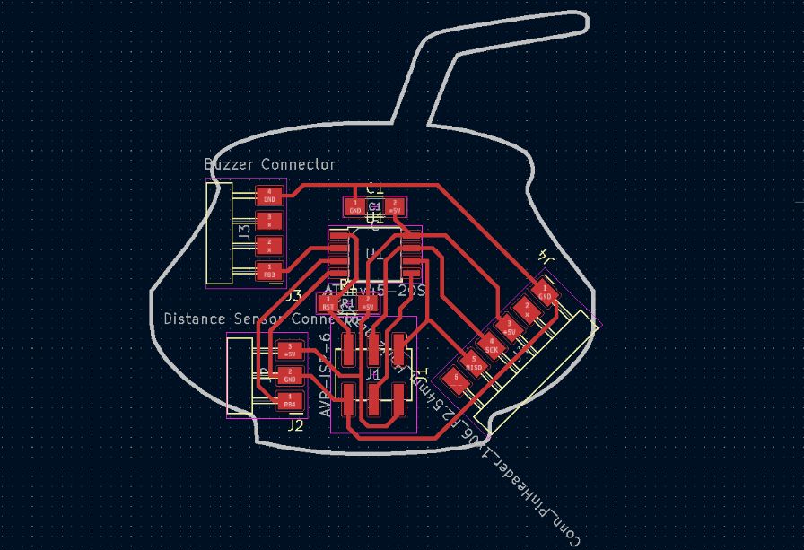 |
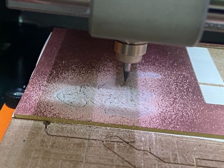
Milling process:
For milling, I just used Fabmods.
If you want to know how I used it, or you want to learn how to use it, just follow the following link. It will direct you to the *Electronic design week, where you can find a very good tutorial of mine.
Programming:
For programming I used the OS Linux, where is a very solid OS for programming.
I tried to program on my laptop that has Windows, but was impossible for me.
| I also used my old trustfull Programmer that I made on the Electronic design week for programming it. |
|---|
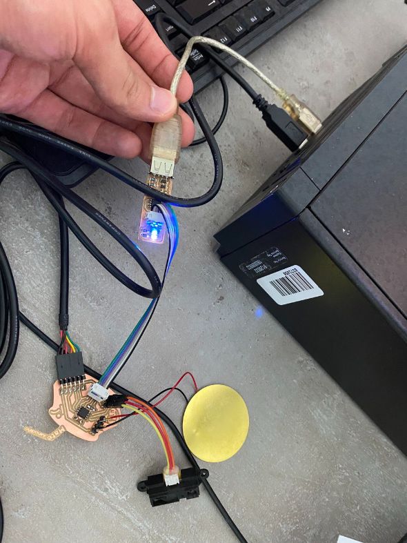 |
| Here you can see the piezzo (output-device) with the distance sensor (input-device) |
Getting different Frequencies:
So for this part, I used a beautiful chord path:
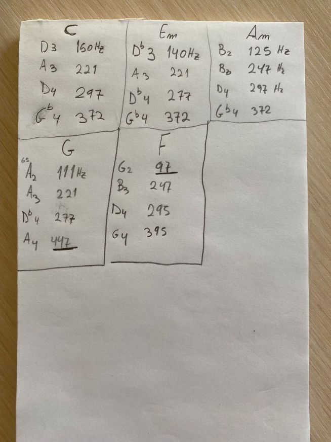
I took this frequencies from the following website
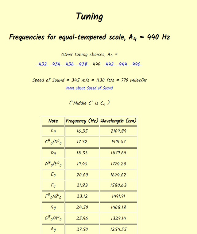
(Source: mtdu.edu)
Once that I had the frequencies that I wanted I installed an app for android called Music Note Identifier
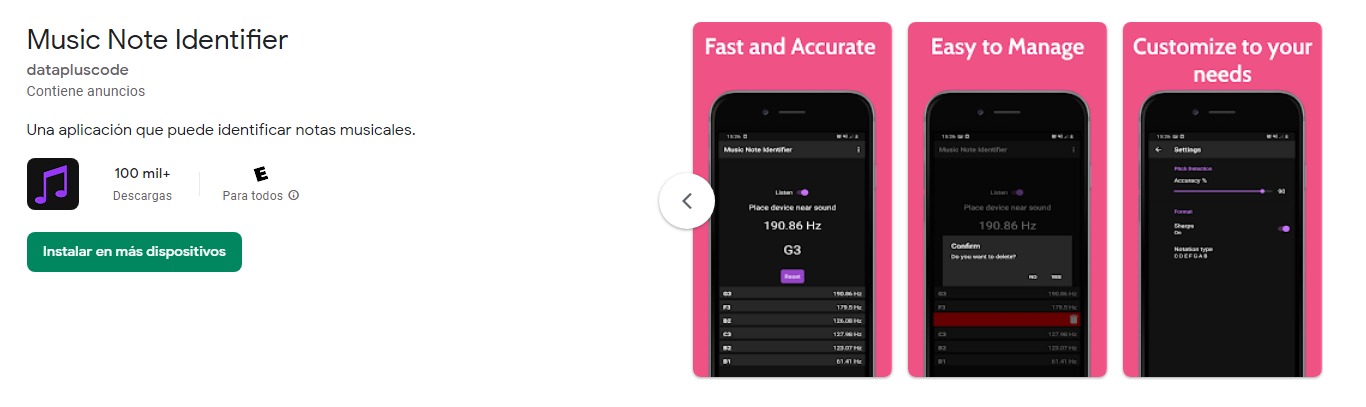
And I started to look for the appropiate frequency:
Code:
Important Note
The code that appears here is the same code for the “Output week” because both weeks are inside of my final project.
Note about the code
Inside of the code you will find the double-bars “//” that will explain the code
//
//
// Theremin
//
// simple software to measure distance and make sound delays
//
// (c) Babken Chugaszyan, Ruslan Gindullin, Ashod Bzdigian 2022
// This work may be reproduced, modified, distributed,
// performed, and displayed for any purpose. Copyright is
// retained and must be preserved. The work is provided
// as is; no warranty is provided, and users accept all
// liability.
//

#include <avr/io.h>
#include <util/delay.h>

#define output(directions,pin) (directions |= pin) // set port direction for output
#define input(directions,pin) (directions &= (~pin)) // set port direction for input
#define set(port,pin) (port |= pin) // set port pin
#define clear(port,pin) (port &= (~pin)) // clear port pin
#define pin_test(pins,pin) (pins & pin) // test for port pin
#define bit_test(byte,bit) (byte & (1 << bit)) // test for bit set
#define Short_delay() _delay_ms(1) // Short delay (CHANGE DELAY VALUE IN MILISECONDS)
#define Long_delay() _delay_ms(1) // Long delay (CHANGE DELAY VALUE IN MILISECONDS)

#define led_port PORTB
#define led_direction DDRB
#define buz (1 << PB3)

short int re;//reading variable

void initADC()
{
  ADMUX =
            (0 << ADLAR) |     // left shift result
            (0 << REFS1) |     // Sets ref. voltage to VCC, bit 1
            (0 << REFS0) |     // Sets ref. voltage to VCC, bit 0
            (0 << MUX3)  |     // use ADC2 for input (PB4), MUX bit 3
            (0 << MUX2)  |
            (1 << MUX1)  |
            (0 << MUX0);

  ADCSRA =
            (1 << ADEN)  |     // Enable ADC
            (1 << ADPS2) |     // set prescaler to 64, bit 2
            (1 << ADPS1) |     // set prescaler to 64, bit 1
            (0 << ADPS0);      // set prescaler to 64, bit 0
}

void delay2micros(short int i){   // Delay microseconds
      while (i != 0) {
      _delay_us(2);
      --i;
      }
}
int valuecleaner(){  // Averaging input to eliminate analog noise
short int i = 0;
int val = 0;
for(i = 0; i < 10; ++i){    // reading 10 times
  initADC();
      ADCSRA |= (1 << ADSC);         // start ADC measurement
      while (ADCSRA & (1 << ADSC) ); // wait till conversion complete
    val += ADCW;
    }
    val /=10;  // dividing by 10
    return val;
    }

int main(void) {

   //
   // main
   //

   //
   // set clock divider to /1
   //
   CLKPR = (1 << CLKPCE);
   CLKPR = (0 << CLKPS3) | (0 << CLKPS2) | (0 << CLKPS1) | (0 << CLKPS0);
   //
   // initialize LED pins
   //
   clear(led_port, buz);
   output(led_direction, buz);
   //
   // main loop
   //
   while (1) {

    if(valuecleaner() < 65) re = 0;  // Capping low values to eliminate noise
    else re = valuecleaner();


      set(led_port,buz);
      delay2micros(5000/re);     // Dividing a constant by variable to linearize the scale and delaying for the result amount of microseconds

      clear(led_port,buz);
      delay2micros(5000/re);  // Dividing a constant by variable to linearize the scale

   }
}
Note about the Frequency
If you want to change the frequency you need to change the values of this part of the code:
set(led_port,buz);
delay2micros(5000/re);     // Dividing a constant by variable to linearize the scale and delaying for the result amount of microseconds

clear(led_port,buz);
delay2micros(5000/re);  // Dividing a constant by variable to linearize the scale
Note about the instrument
The process of changing the tone (frequency) is still rusty and maybe a bit tedious to do. Because first you need to change the value, and then look into the app for the correct pitch.
I’m planning to find a better way in the future.
Some problems
My first PCB model was good, but it has a “tiny” problem:
I had a “stupid mistake”. I forgot to put the pad for FTDI cable:
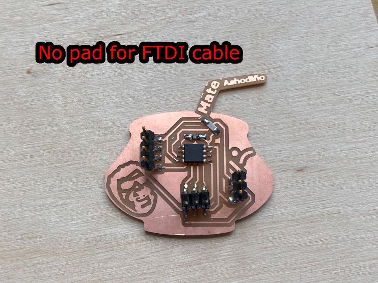
So I had to design my schematics again, with another wires and PADS.
And yes, it took longer than expected.
Testing Input and measuring:
As the distance sensor is going to be my input device, and the output will be a piezzo. There is no need to check if my input works with a program, due to the piezzo will be the main tester.
For checking my Output week, click here.
| I needed to test the frequency of the tunes |
|---|
| For this, I looked in internet some chords |
|
| And I start testing with a Digital Oscilloscope |
 |
 |
Files:
Code
For the code, just go to the section “Code” in the content bar, and copy it. There is a button on the top right corner for easy copy.