12. Output devices
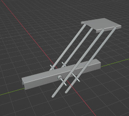
For this week assignment I made a small model of my final project, the Idea is to start exploring the best way to make the moving part of my final project. I decided to use two servos that will move at the same time to move the paralel bars that will hold a lid.
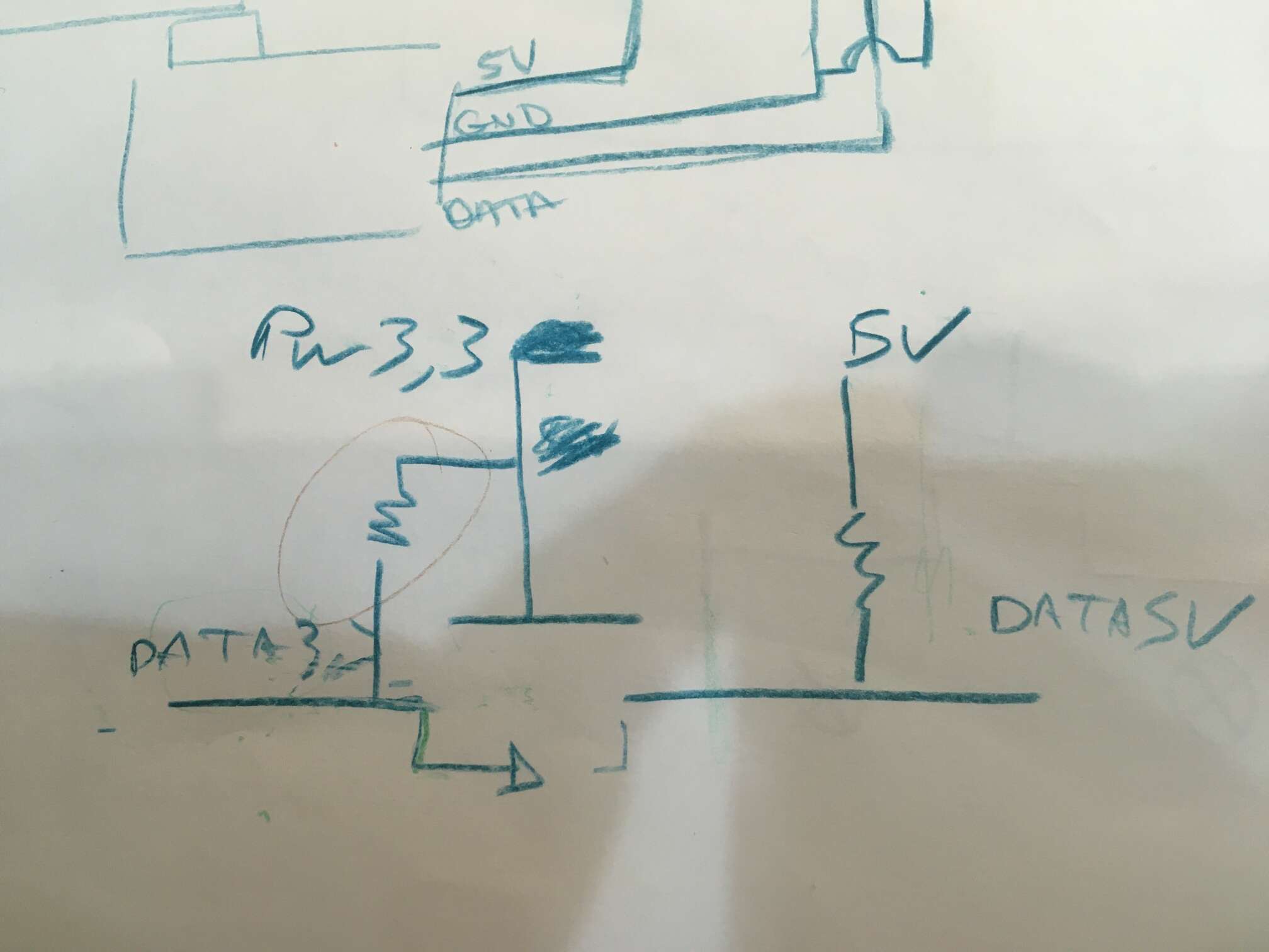
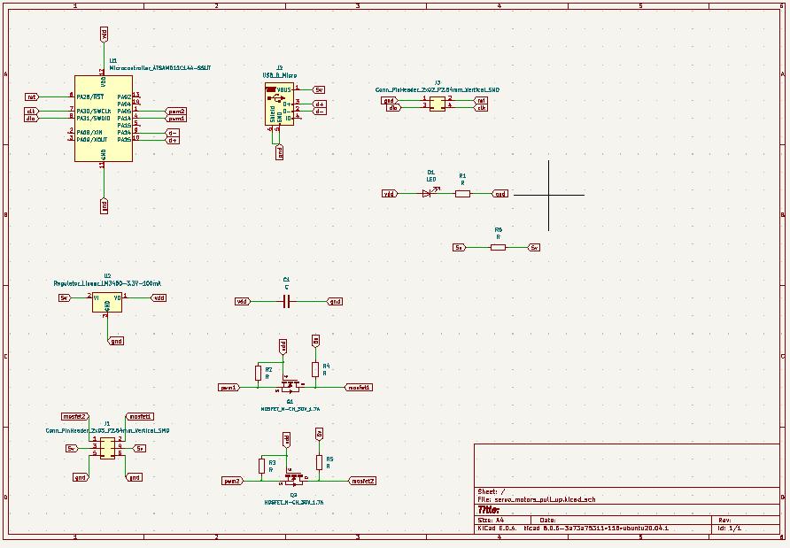
To make the servos move I am going to use the SAMD11C214A, this microcontroller works at 3.3V and the servos work at 5V so I am going to use some mosfets to make a level shifter to be able to send the signal to the servo at 5V.
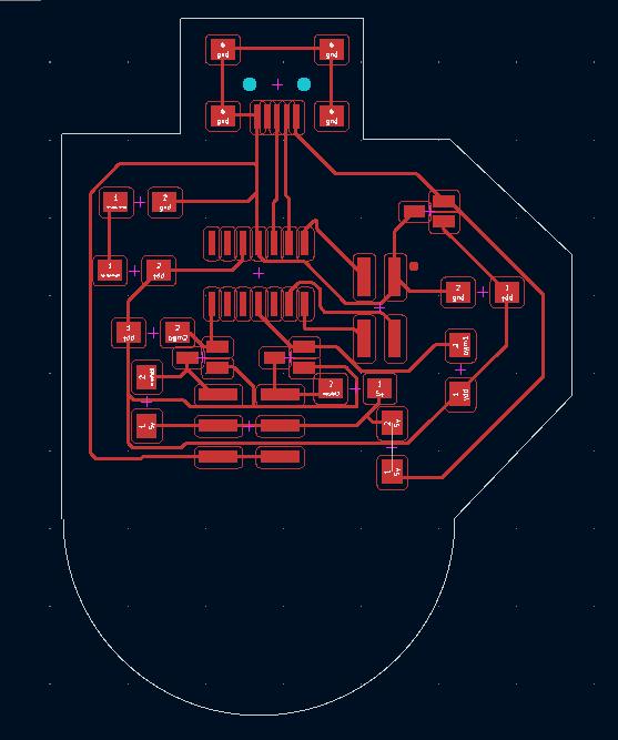
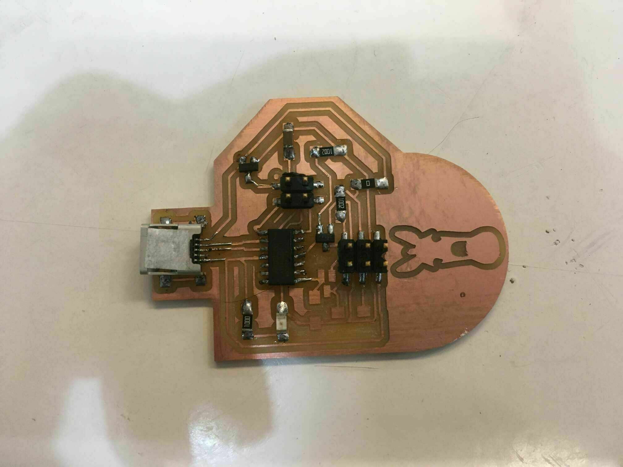
I decided to cut this board with a small CNC thas uses GRBL and I had to look for a software that let me controll the machine via USB with my computer, I found BCNC. This tool will let us controll the machine directly, we can put diferent files and acomodate them in the bed of the machine in just one operation.
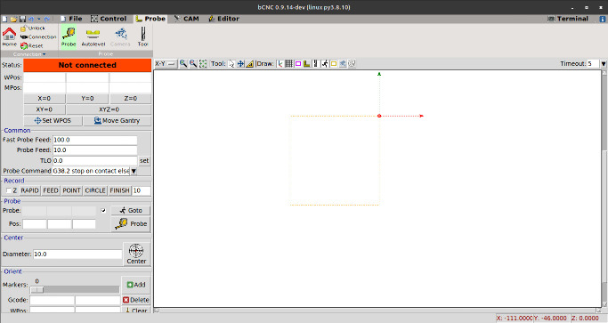
The software works really well, but the thing is that the machine is not as fine as the ROLAND srm20 because the Z azis has a lot of movement and it brakes all the small traces of the PCB, I had to repeat the board several times triing to tune the machine. At the end I just cut the board in the roland because the machine needs an update to make it better.
Some code to move the two servos simultaneously
int noPin = 7;
int angle1 = 2000;
int angle2 = 500;
//int lecture;
//int lastangle = 500;
void setup() {
  // initialize serial:
  Serial.begin(9600);
  // make the pins outputs/inputs:
  pinMode(14, OUTPUT);
  pinMode(11, OUTPUT);
  pinMode(noPin, INPUT);
}
void loop() {

  Serial.println(digitalRead (noPin));


  if (digitalRead(noPin) == 0) {
    digitalWrite(14 , HIGH);
    delayMicroseconds(angle1);
    digitalWrite(14 , LOW);
    delay(50);
    //Serial.println(angle1);


    digitalWrite(11 , HIGH);
    delayMicroseconds(angle1);
    digitalWrite(11 , LOW);
    delay(50);
    //Serial.println(angle1);
  }
   else {
    digitalWrite(14 , HIGH);
    delayMicroseconds(angle2);
    digitalWrite(14 , LOW);
    delay(50);
    //Serial.println(angle2);


    digitalWrite(11 , HIGH);
    delayMicroseconds(angle2);
    digitalWrite(11 , LOW);
    delay(50);
    Serial.println(angle2);
  }

}
Using the serial we can send the position to the servo, but in this case I am using an input to move the servos. The input is the rain sensor, that is quite easy to work with because the sensor just sends a 0 or a 1 depending if the rain sensor is triggered or not.
What the code does is changing to one position to another the servos (from 0º to 180º). With the SAMD11C I can’t use the servo libraries, so I have to find another way to move it. To do it I have to simulate a PWM using HIGH and LOW with a delay between 500 and 2000 microseconds (dealyMicoseconds).
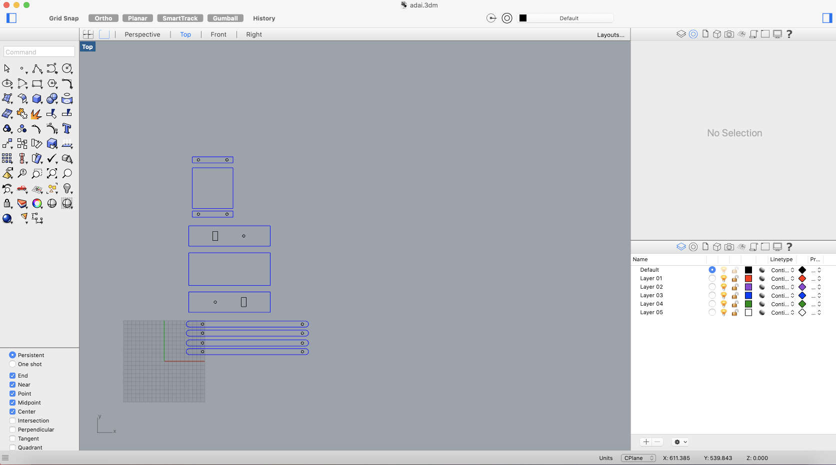
Once the electronics were solved I stared making an structure that looks like the final project to cut it in the laser and know how much weight are capable to move those motors, and make an idea on which motors I will need to make the final machine.
Here the pieces I laser cuted to build the structure.
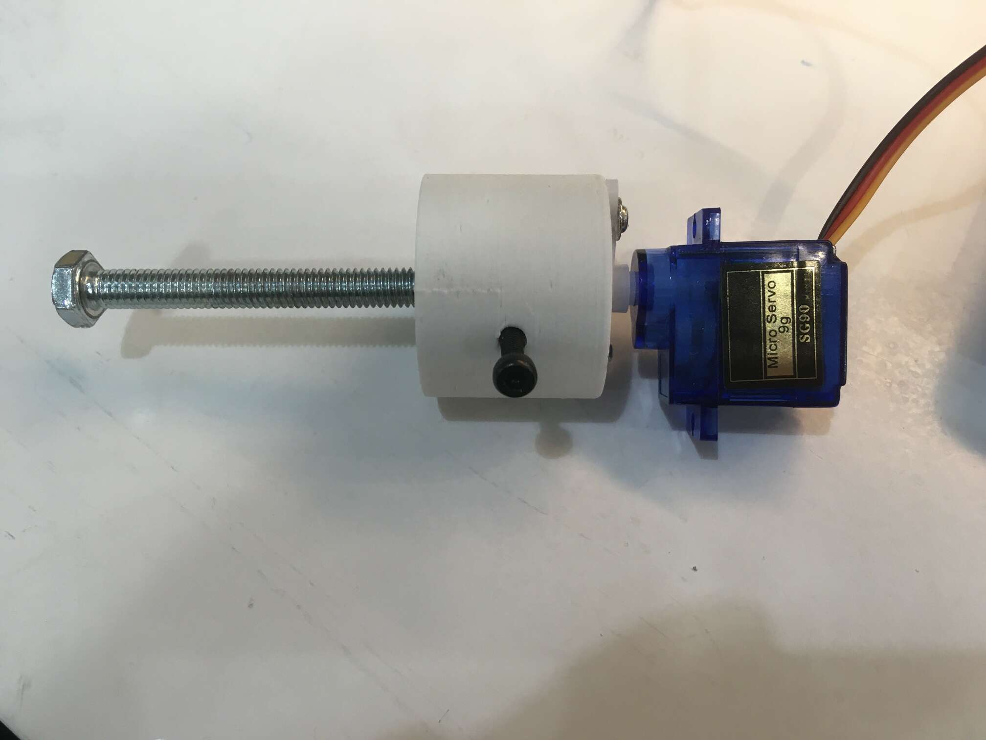
To attach the motor to the moving parts I designed a very simple joint that allaws the motor be attachet to the main structure and rotates free in otder to move the lid from one side to another.