8. Computer controlled machining
MAKE SOMETHING BIG!
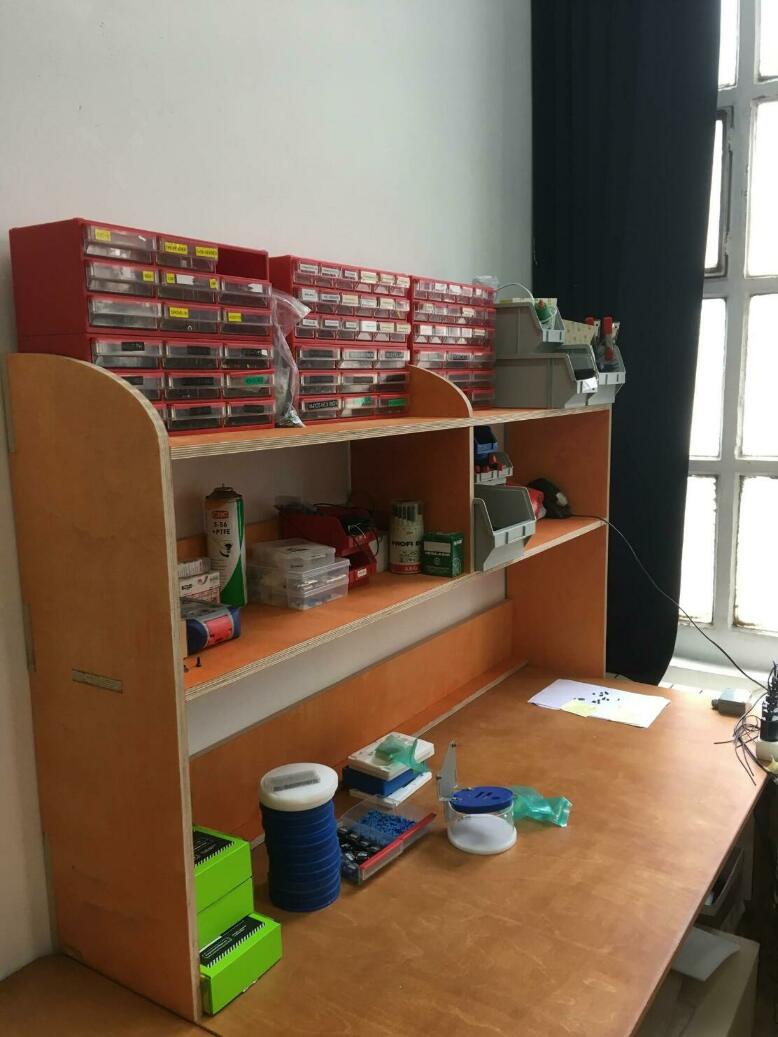
This week we need to make something big, so I decided to make a pice of forniture.
The piece that I have made are those shelfs that fits on top of the table, the idea is to have some space on top of the table to put some of the drawers that we use to keep screws and tools organized leaving the space of the table to work confortable.
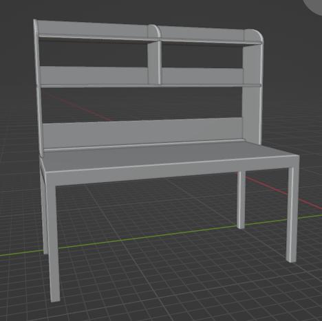
To design the shelfs I took the mesurements from a desk that we have in the office, which is a desk form open desk and started to work with blender to make a design.
This is the first version of the shelfs but, the problem was that for cutting it 3 full size boards of 2500mm x 1250mm were need it, the price of each board is about 150€.
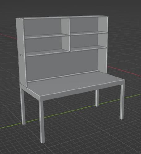
The next version was about to reduce the material to make the shelfs much cheaper, I started splitting in 3 the board of the back part to make that previously was almost a full size board, after I realized that the top shelf does not need the cover so i colud make the shelf a little bit lower, and round a little bit the top part to make the side pieces eaven smaller.
Finaly I finished beeing able to fit the hole piece in just one board.
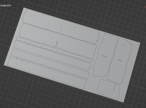
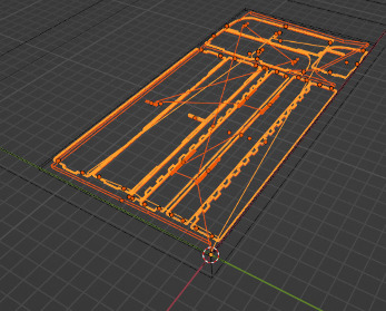
this is the cam view I prepered with blenderCam to send to the machie.
To cut all the pieces all the pieces I have used a 6mm end mill down cut with a flat end.
| Spindle | Movement |
|---|---|
| 23000 rpm | 3500 mm/min |
| To calcucate the feeds and speeds I use the calcuator from the tool fabricant. |
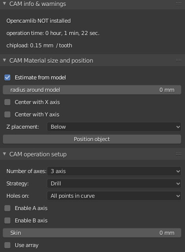
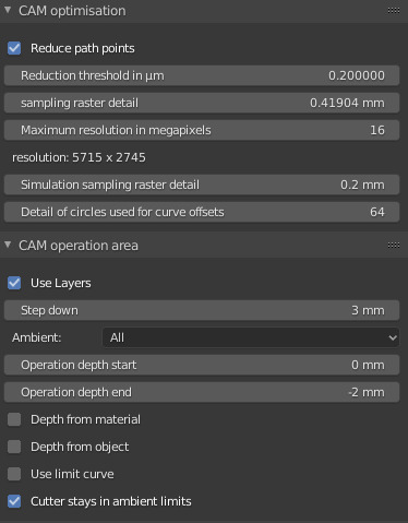
The wood is quite hard so I have to keep low the Step down (how many mm of material are cutted on each pass) in this case is 3mm for the profiling and for the pocketing.
Blender Cam has the option to make automaticly the dogbones to make all the joinery fit correctly, and lets you choose different tipes.
To make all the joins fit corrrectly once with the others I gave some offset to all the joinery, in this case everything is 0.05mm smaller that should be to fit corrctly.
remember all the aoulines have to be cut outline and the pocketings inline.
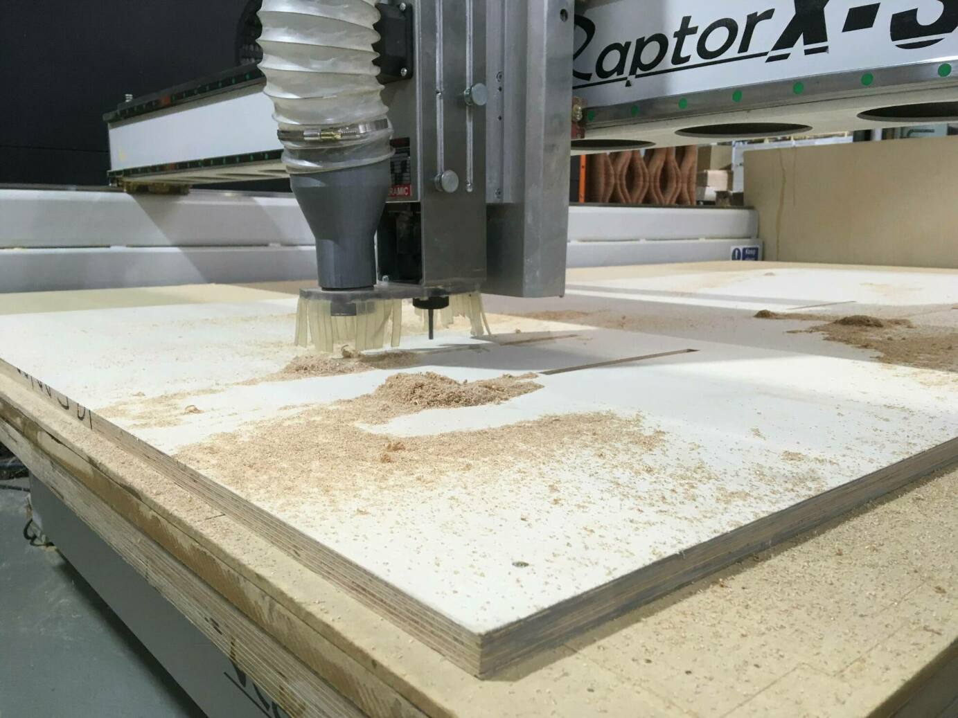
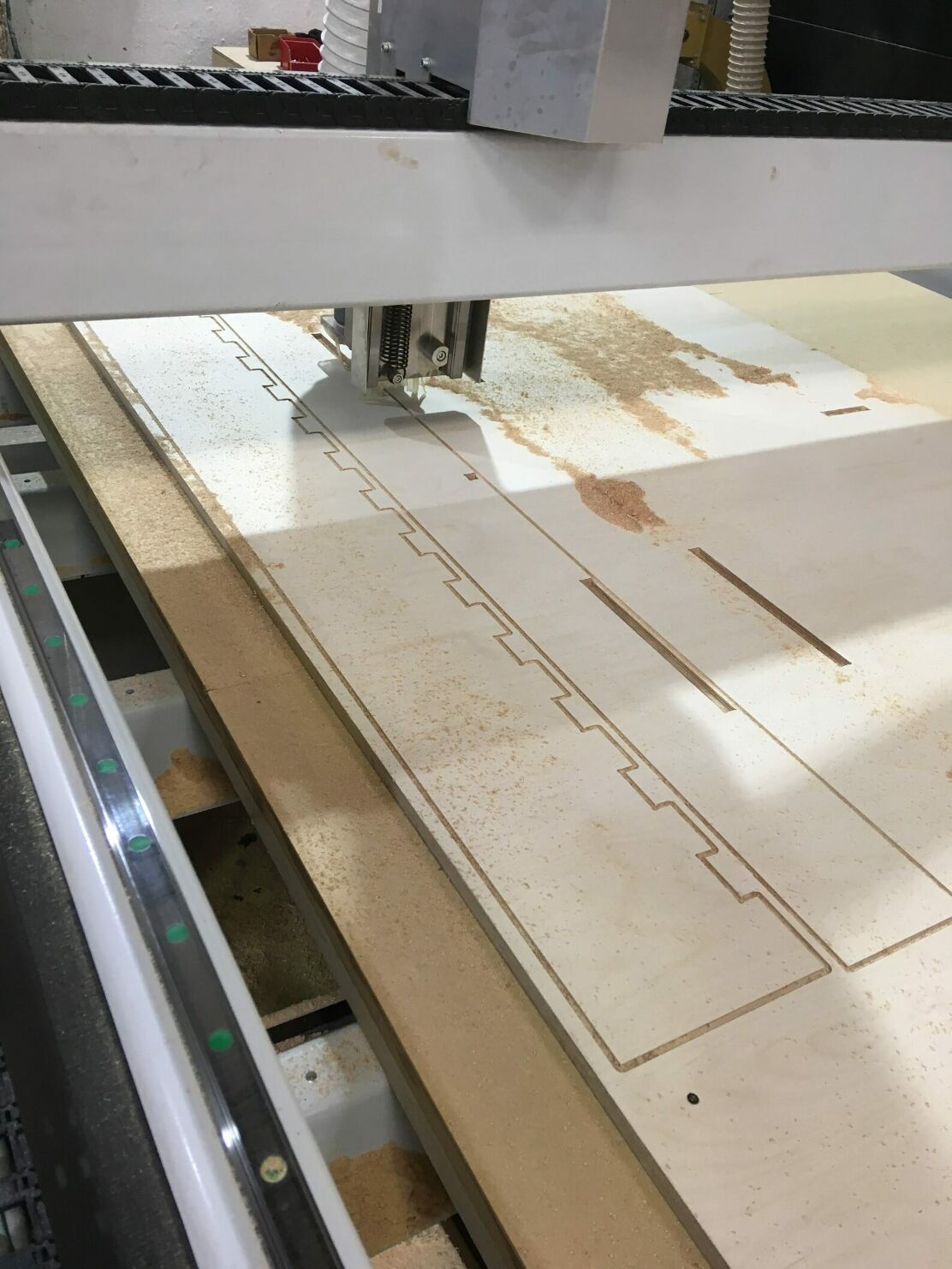
Some pictures of the machine in progres
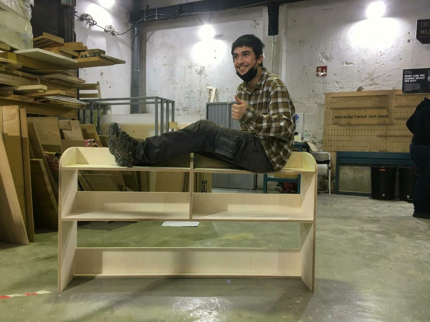
Surprisingly the piece holds me only with the wood joinery!!
And finaly some varnish painting to make it durable and get a nice color.
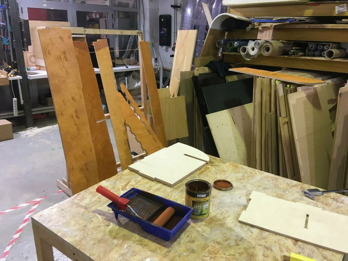
Ready to go to the final place and get ready to work!
How to intall blender CAM add-on on Linux
Blendercam is an addon of Blender. It works now with Blender version 2.83 and 2.92 and 3.0. You can download Blender portable version for linux64 2.83 or 2.92 and install dependencies from command lines.
$ ./pip3 install shapely
$ ./pip3 install vtk
$ ./pip3 install Equation
The second step is to tell blender to also search an alternate path for add-ons. When blender starts up it will search its own paths for add-ons and will also search the alternate path that you add. This way an external source add-on can be used in Blender.
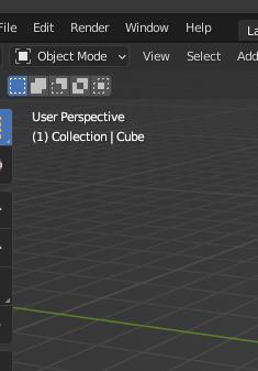
-
select User Preferences panel
-
select File Path
-
select the file button on the Scripts input field and select the path to your blendercam/scripts directory
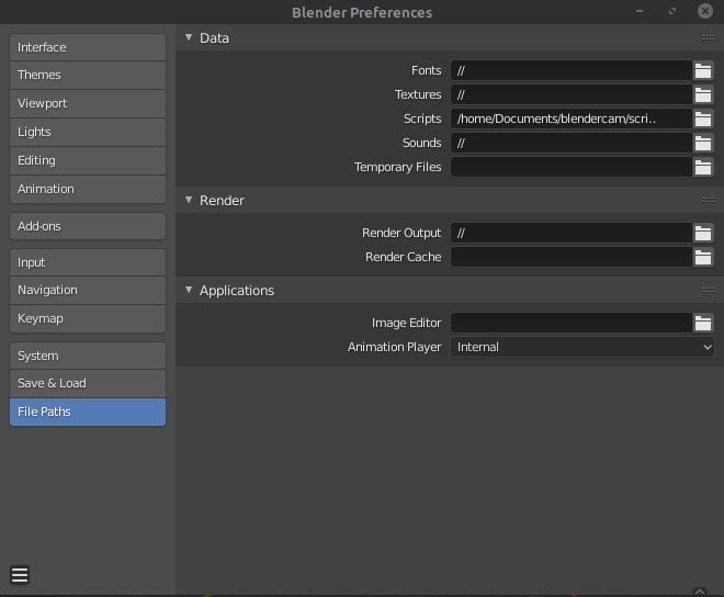
-
Save perferences
-
restart blender
Enable Blendercam add-on
The third step is to anable the Blendercam add-on.
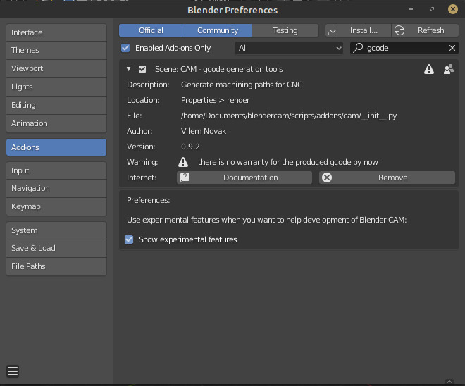
At the same place (Blender Preferences) as de File Paths you can anable the Add-ons of blender.
-
selecte the Scene category
-
enable the CAM addon by left clicking on the check box. (the file path should match your Blendercam git path)
-
Optional: enable the experimental features
-
save user settings
To see a more detailed tutorial of all the tools and how to do all the strategis of the cam (profiling, pocketing, drilling) you can visit here and here.
If you follow this documantation you will learn really fast how to make you paths. the only thing that may cause som problems are the postprocesor you machine may need.
BlenderCam offers a bunch of allready made postprocesors, the best way to get yours is modifing an existing one, I had to canhe one archive adding a “%” symbol at the top and adding a new line “.\n” for each M command. Just adding two simple things tha postprocesor was ready to go.
There are some isus with the Silhouete offset tool, when you estract a silhouete from an object the curve generated is not very clean and there are a lot of duplicated vertices, the best way i have found to solve this problem is to convert this curve in to a mesh again and merge the vertices by distnce to eliminate the duplicated ones. Finaly convert again the mesh to a curve.
If you don’t clean the curve, when you try to add the Overcts or T-Bones you may have some troubles. Despite this check all the corners if everything has been as you planned because there is one corner that may have an error. If you go on edit mode in a curve you will see that the cuve has one start and one end, and this may cause a problem, if you duplicate one of those two and snap in one on top of the other, in order to have the start and the end at the same point may solve some issues. If you still miss some of the dogbones just convert the curve in to a mesh and merge all the vertex by distance, this will clean the mesh. Return to a curve and all the problems shoulg be solved
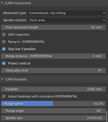
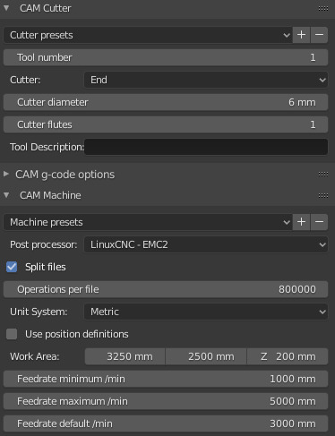
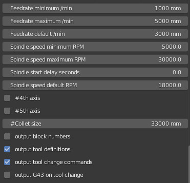
Last thing you have to remember before explorting your cam file is to enable an option in the CAM movement menu called Fist down to make the machine start a piece and finish it before starting another one, otherwise the machine will make the first layer of each of the pieces, then the second and so on until the last and you will lose a lot of time traveling from one piece to another without cutting anything.
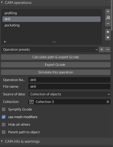
Here the settings of my blenderCam.
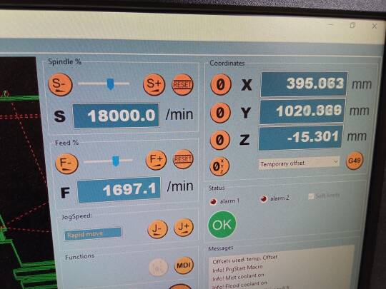
Cutting
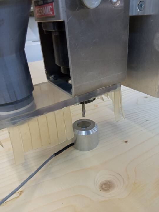
To set up the machine is necesary to save a new origin in our material. When we resart the machine, this may not know where is the actual position, it will need to go to the absolute cordinates home (0, 0, 0). Once the machine is in the 0 position we can move it to the corner we want to make our origin (relative origin) using the computer next to the cnc and save the position in X and Y.
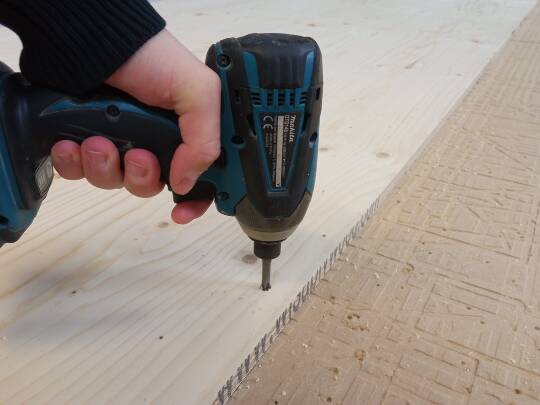
To save the Z position is better to move to the center on the material we are going to cut, to do this we are goint to use the button that is normalt placed next to the comupter. Place the button under the drill bit an press the custom set up to find the Z origin.
Now we can start the operation to place the screws, once this is done, put the sxrews in and do the Z origin again because this may have changed a litte bit when we have put the screws in.
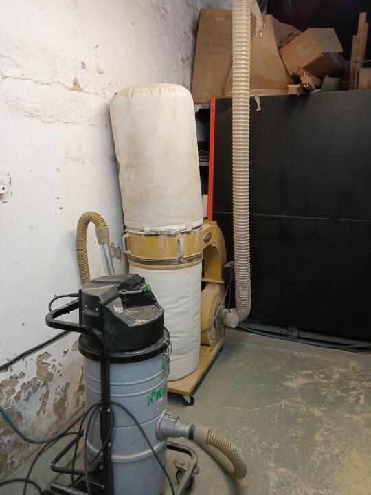
Remember to start the vacum to collect all the dust while cutting.
Now it’s the moment to stat the cutting files. If your files have pocketings is better to do them firtd and then the cutting files.
Remember to keep an eye on the wood and in the computer to check if everyting is going as planned