11. Input devices
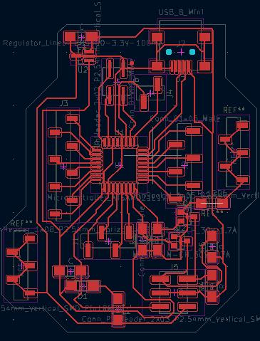
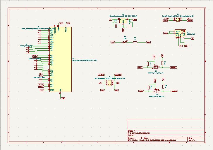
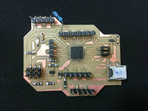
For my inputs assingment I have been working on the board that I expose all the pins of he samd21E the board I made is quite simple, there is the USB connecton to program the board, the 4 pins to burn the bootloader, two connections to connect two servos at 5V, some pins at 3V3 and some GND and finaly all the pins of the samd are esposed to be able to connect inputs and outputs.
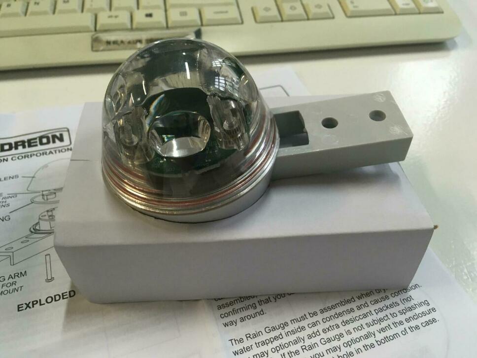
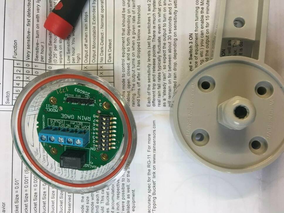
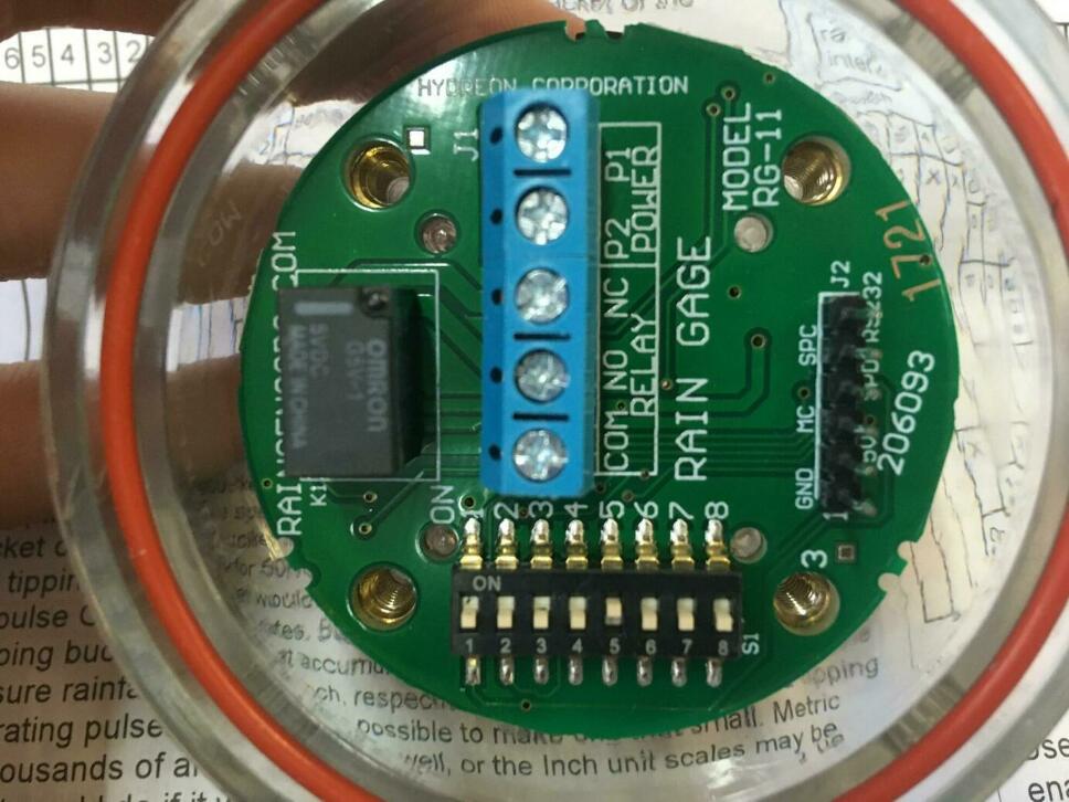
I am going to use as an input a rain sensor that in theory have to send a signal when a drop falls on top of the sensor, but is not that easy, the rain sensor has different modes of working that is controlled by some switches that are located in the encosure of the sensor. The datasheet of the sensor explains quite well the different modes and the usability for each mode.
In this case the sensor has to detect the firt drop and be quite sensible to able to get the fastest lecture and send the signal to the microcontroller. If we look at the data sheet there is one mode that is exactly what we want, also we can tune a little bit the mode: there is one options to put a heating system to aboid condensation on the sensor and read a false signal, and another one that makes the sensor wait 15 minuts to calibrate it self before making any lecture, and others that i tried. Once i had tried all the modes and the convinations in each mode I found that a simplest one was the most efective.
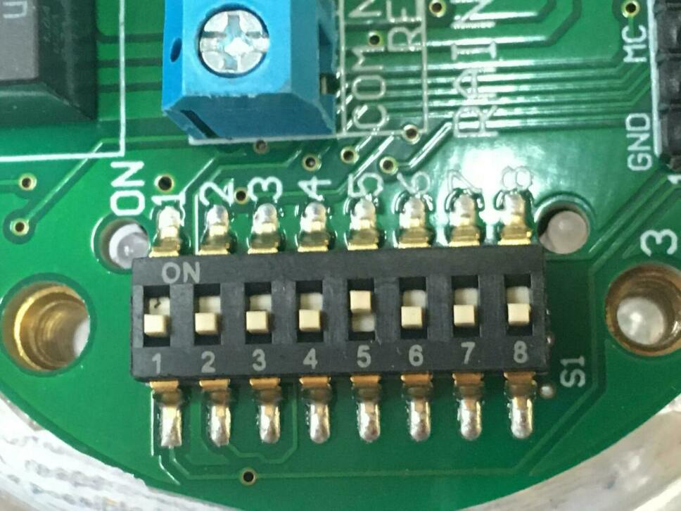
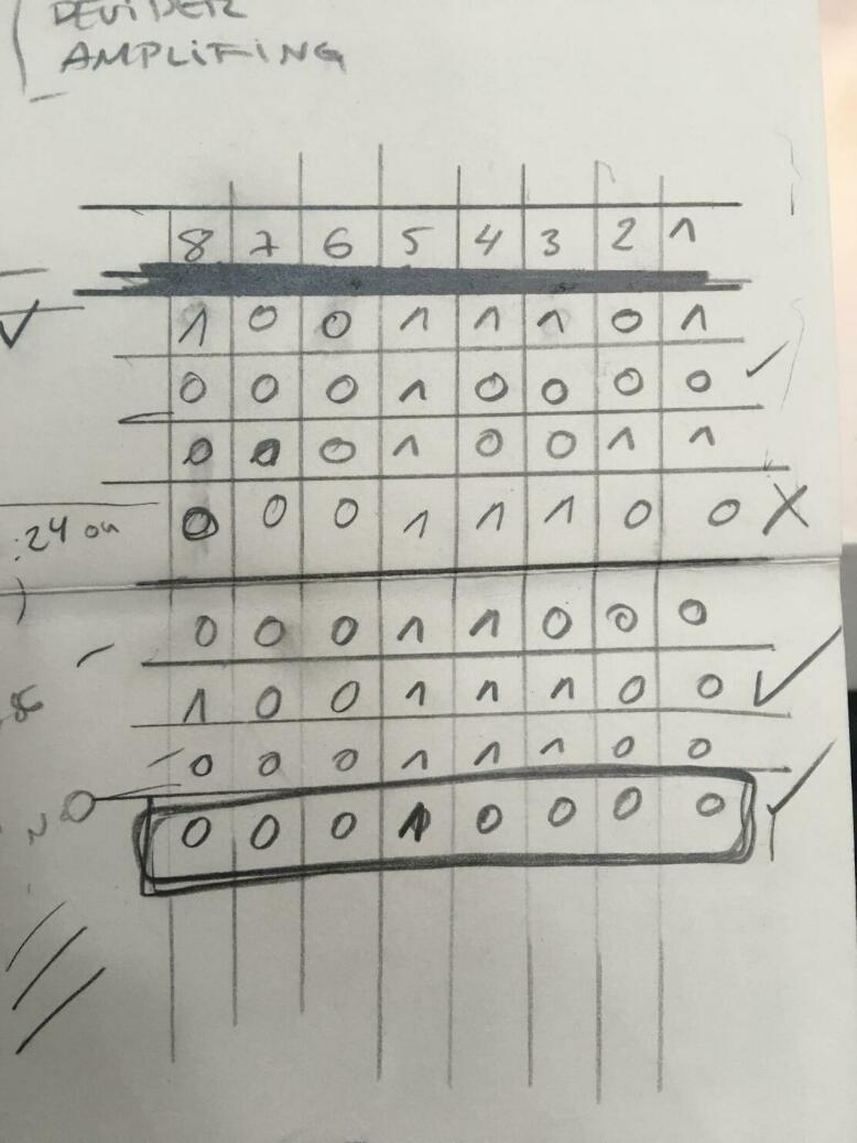
All this took me a lot of time because I misunderstood some information of the datasheet and not everything worked as planned. But finlay I reached the good position of the switches.
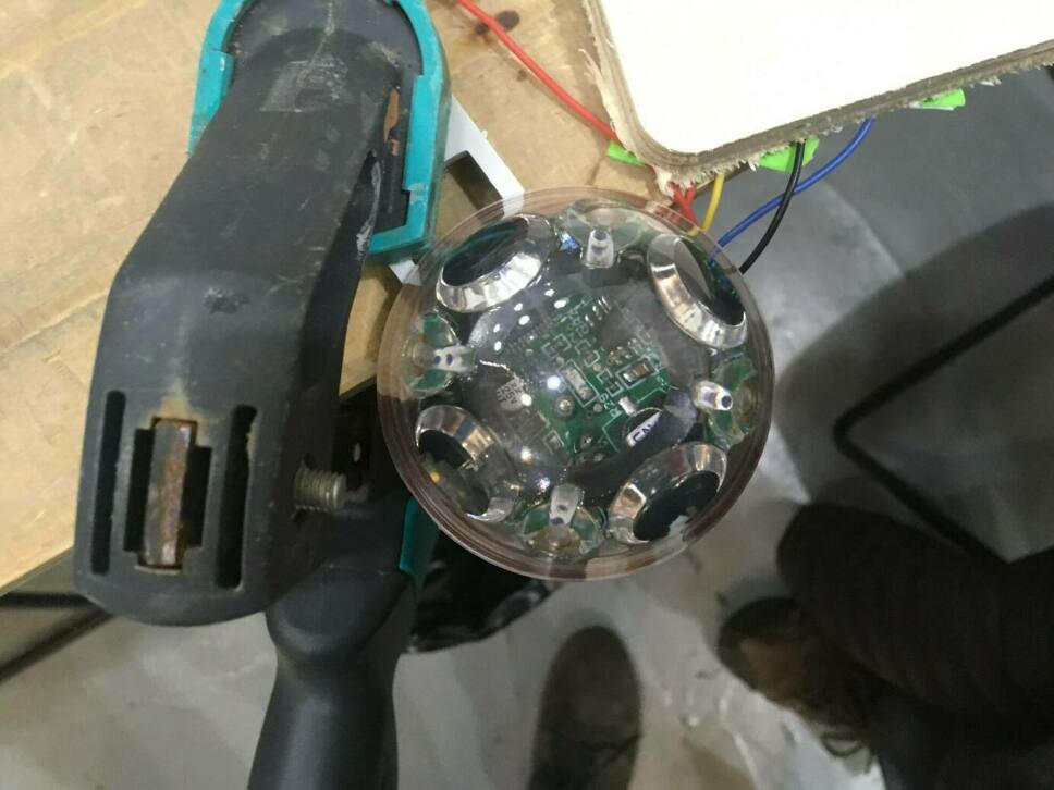
This sensor is based on how the light bounces on the acrilic enclosure, when nothing is on the sensor the light bounces on a particular way that, when a drop falls on the sensor the bounce of the light bounces in a diffent way and the sensor reads this as it is raining and sitches a relay that sends you the digital signal.
The sensor is conected using two cables to the board, one that is connectd to power (3.3V) and the other one that is connected to a pin, in my case in an analog pin but could be connected in a digital one. The one that is connected to the pin is the NO (normay open) of the relay, there is the option to connect both (Normaly open and Normaly closed) to dubble check if the state of the relay.
Once I started to try the sensor I was reading lots of diffent numbers, and I realized that I had to solder a 10kΩ resistance between the pin that I connectet the sensor a the GND to make a pull down and be able to read the sensor correctly.
Once I was able to read the sensor correctly I was only reading 1 when the sensor was dry and 0 when the sensor is wet.
The Idea for this sensor is to activate a motor that is going to move a lid from one bucket to another one next to it. Now the next thing that has to be done is add a button to reset the system once the movement has been done, I dont want to make tha machine come back alone because I want this to be manual.
CLIK ON THE NEXT IMAGE ↓↓↓
To read the sensor I use a simple code to read the digital signal the sensor is sending:
int noPin = 7;


void setup() {

  pinMode(noPin, INPUT);
  Serial.begin(9600);
}

void loop() {

  Serial.println(digitalRead(noPin));
  delay(100);
}