3. Computer Aided design
This week I have been working in 2D and 3D design. To explore this all this topics I have been exploring different software programs.
2D
To start working with the 2D designs I have been working with Inkscape because it’s an opensouce program with lots of possibilities. Thanks to all the extensions that the program has, you can generate G-code inside the same machine or generate a file to make an embroidery machine work.
What I have been exploring in Inksape started with a simple drawing to start knowing how the program works.

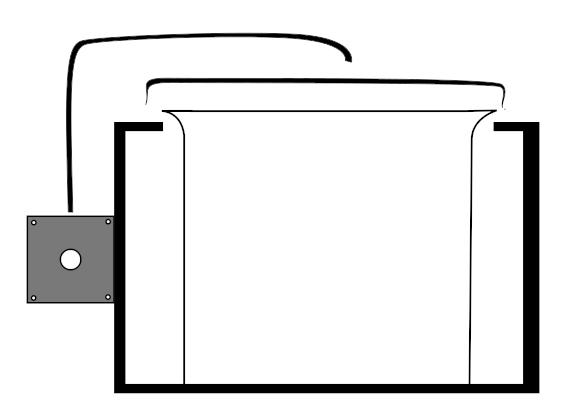
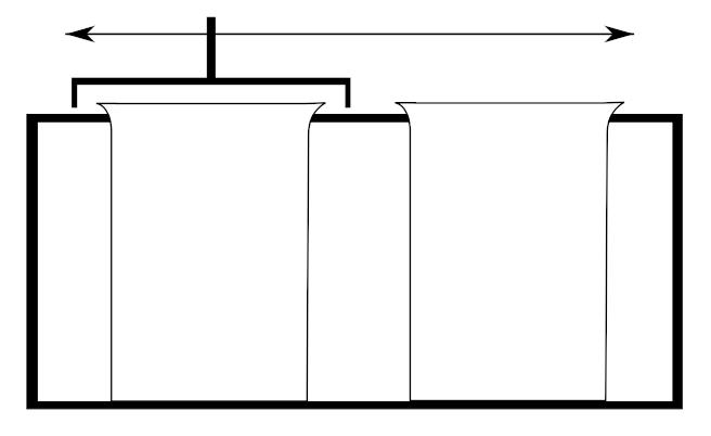
After that first try, Is tried to make a very simple design of what could be a front and side view of the final project machine I want to make. Inkscape is not thought to make CAD drawings, and the result is a little child drawing.
Most of the tools I have been using are in the same menu called path. Where you can find tools that will help you to make different shapes merging two or more geometries.
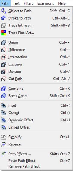
Union: Keeps the common outline of all selected paths.
Difference: Subtracts one path from another one.
Intersection: Only keeps those parts that are covered by all selected paths.
Exclusion: Keeps those parts which are covered by an odd number of paths (if you have two objects, this is where the objects do not overlap).
Division: The path below is cut into pieces by the path above.
Cut Path: Creates as many paths as there are path intersections between the two paths.
Combine: Keeps all parts, and combines them into a single object.
Break Apart: If a path consists of a number of independent parts (subpaths), this will create that number of separate objects.
3D
When I jumped to the 3D printing modeling, I was thinking of making the models in different softwares, so I could learn different workflows. I started with Blender which is a program that I have been using for one year more or less, and I can work quite well, but, I wanted to try other programs to start knowing different workflows so I tried to work with openSCAD because both programs are opensource and there is a big comunity arround them that will support you and will be really easy to find information.
OpenSCAD
In my opinion OpenSCAD is a tool which is not made for making unique and complex objects, is great to make parametric designs that you need little changes, but they are almost the same, something like gears, pulleys and stuff like this is a nice tool, but you need to be quite good at coding and very organized to not get lost during the process.
I have been following some tutorials and the tools are quite similar to other softwares, finally you end up using boolean operations, and you can get some impressive objects if you take your time. There is a CeetSheet that will help you a lot if you are new to this.
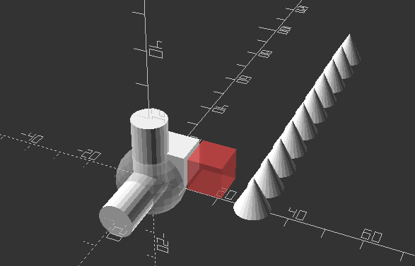
This image shows some basic commands you can use in openSCAD and below all the text commented to know how it’s made.
// "%object()" makes transparent and does NOT APPEAR in the final compile
// "#object()" makes transparent red and APPEAR in the final compile

//Facet Number
$fn=25;

//CUBE
cube([10,10,10]);//three values([distance from origin for each axis])

//SPHERE
%sphere(10); //only one value (radius)

//CYLINDER
cylinder(r1=5,r2=5,h=20);//three values (r1=bottom radius, r2=top radius, h=height)

//TRANSLATE (move the origin)
translate([11,0,0])
#cube([10,10,10]);//three values ([one for each axis])

//ROTATE
rotate(a=90, v=[1,0,0])
cylinder(r1=5,r2=5,h=20);//two values (a=angle v=[axis where you apply rotation])

//for() LOOP (interate)
for(i = [0:10:90]) {
translate([30,i,0])
cylinder(r1=5, r2=0, h=10);
}//need to set value (i) with three values inside [start point, number of objects, final point]
//
//PREVIEW with f5
//COMPILE with f6
$fn=90;
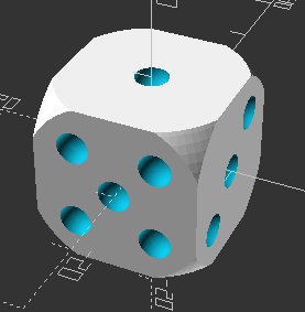
difference(){
//makes a difference boolean, the first object is the one where the booleans are going to be aplied
// dice body
intersection(){
// makes a intsersection boolean, Creates the intersection of all child nodes. This keeps the overlapping portion (logical and)
cube(20,center=true);
sphere(15);}
//face number 1
translate([0,0,10])
sphere(2);
//face number 3
translate([10,0,0])
sphere(2);
translate([10,5,5])
sphere(2);
translate([10,-5,-5])
sphere(2);
//face number 2
translate([-5,10,-5])
sphere(2);
translate([5,10,5])
sphere(2);
//face number 4
translate([-10,-5,5])
sphere(2);
translate([-10,5,-5])
sphere(2);
translate([-10,5,5])
sphere(2);
translate([-10,-5,-5])
sphere(2);
//face number 5
translate([-5,-10,5])
sphere(2);
translate([5,-10,-5])
sphere(2);
translate([5,-10,5])
sphere(2);
translate([-5,-10,-5])
sphere(2);
translate([0,-10,0])
sphere(2);
//face number 6
translate([5,5,-10])
sphere(2);
translate([5,0,-10])
sphere(2);
translate([5,-5,-10])
sphere(2);
translate([-5,5,-10])
sphere(2);
translate([-5,0,-10])
sphere(2);
translate([-5,-5,-10])
sphere(2);
}
I had some problems using this software because I’m not used to write code, so it’s quite new for me. But it’s quite motivating learning new softwares and different ways to work I see lots of possibilities in this program that in others would be quite difficult, parametric designs for example.
Blender
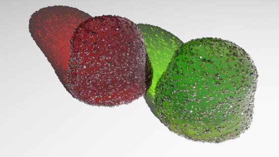
Blender is a program that I am quite used to work with, so I can manage quite well modeling with it. Now with blender 3 there are some new features like the geometry nodes that I am trying to learn but is quite a slow process. I have been following some tutorials to learn the new features.
This is a render of an image totally made with the geometry nodes.
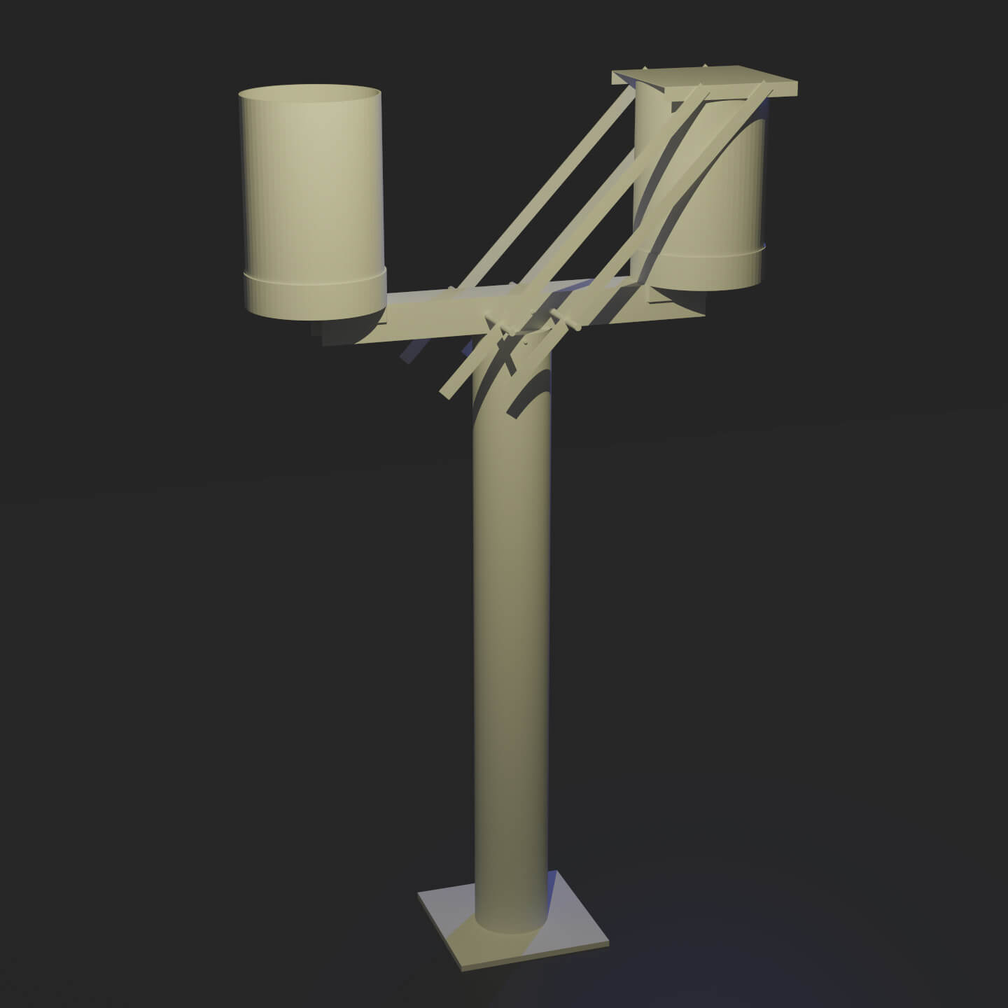
In the next image, I make a more detailed of what would be the idea for my final project.
—
It’s good to start using progams we don’t know much about to see other ways to make the same thing, that can be easyer or not but we will see and learn different ways to work. In this case using openSCAD has been quite helpfull for me to see a complete diferent way to build some objects. For me is quite difficult but make me understand the basics of 3D modeling.