4. Computer controlled cutting
Group assignment
This week we learned how to use the laser and the vinil cutter. The objective is to make some templates of diferent materials in group to control the diferent power and speeds of the laser and make some tests to control the tolerances, the kerf of the machine and learning how to focus.
Here is a link where you will find the group assignment documentation.
Assignment
After this group assignment we need to design a parametric press-fit kit “game” with the knowledge we got in the first part of the assignment, taking account of the different parameters learned we have to take account.
The second part of the assignment is to make something to learn how to use the vinyl cutter.
OpenSCAD
To design the press-fit kit i decided to go with openSCAD (taking acount that i don’t know much about coding it was an adventorous option) and I sufferd a lot. The first thing I started with was making a circle circle( r = 3 , $fn = 5 ) this gives us a polygon with 5 faces bit wewant to take control of the points that makes ouer polygon, with the circle() we don’t have this possiblily. After this with Edu started learning how to move trough the software a little bit better, istead of creating a triangle and rotating it, we genated a point in a variable distance height that we could control, once we have this point is thhe moment to rotate it and gererate all the points of the polygon that finaly will be closed.
After trying a lot ot ways how to do de cuts for the fit-press game on the already generated polygon, i found a documentation page where there are lots of different examples and exercices with the code to replicate it.
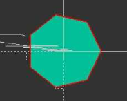
This is the code to make the only the polygon
  height = 10;
sides = 10;

points = [ for (i = [0:sides]) point(height, 360 * i / sides)];

function point(rad, angle) = [height * cos(angle), height * sin(angle)];

polygon(points);
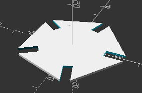
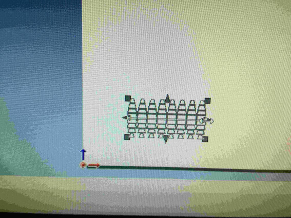
This is the code with the difference boolean for the press-fit kit
height = 25;
sides = 5;
fit = 4;
length = 10;
totallength = length * 2;


points = [ for (i = [0:sides]) point(height, 360 * i / sides)];

function point(rad, angle) = [height * cos(angle), height * sin(angle)];

difference(){
polygon(points);

  r = height; // pattern radius
  n = sides; // number of holes
  step = 360/n;
  for (i=[0:step:360]) {
      angle = i;
      dx = r*cos(angle);
      dy = r*sin(angle);
      translate([dx,dy,0])
      rotate([0,0,angle])
      square([totallength,fit],center = true);
  }
}
Laser cut
Once the files were prepered the final step is to laser cut the files, first I need to export the files from openSCAD to rhino wich is the program the computer that controls the laser cutter uses to send the files to the machine.
The last things to rember before you send all the files to Job Control (the software we use to manage the laser jobs) are:
- Join all the curves
- Remember to make curves in 2D
- Change colors to make the laser work i a correct order
- Focus the laser using the spacer placed next to the laser
- Place the material and set the origin using the control of the machine
- Open the air exhaust
Now it’s time to put the laser to work, afer a little try to see if the laser has the correct speed and power, in this case was MDF and I used power at 50% and speed at 0.5% althow those paramaters may change depending on the state of the laser lens.
(Before cutting a file cut an small squere 5mm by 5mm to see if the power and speed is ok, then you can cut your file)
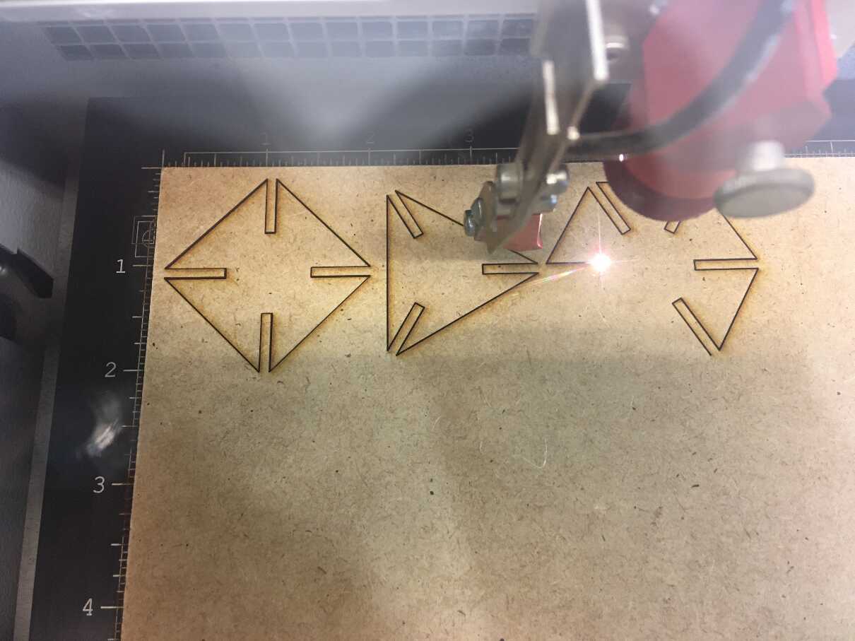
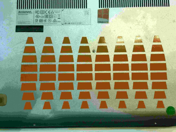
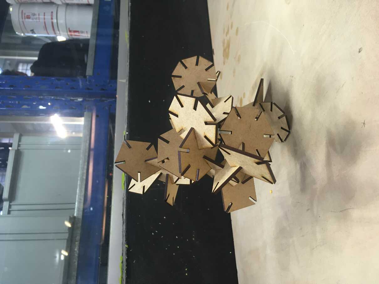
Afer this fist cut which i cut only one polygon of each from 3 to 8 sides to see if he joins went well. In this case everytnig was fine. Afer this first try I cut the some more pieces to make a little set to make a king of construcction game.
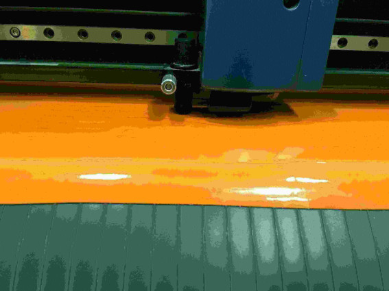
Vinyl cutter
Steps to follow to cut in the Roland:
-
Load Material on the cutter by releasing the holding tab from the back.
-
Set the width limit sensor at the correct mark.
-
On the GX24’s interface, set the correct material feed type by clicking. In our case, it was a piece. The other option was roll.
-
Waited for the machine to measure the length of the material.
-
Installed and calibrated the cutting tool.
-
Set the desired cutting speed.
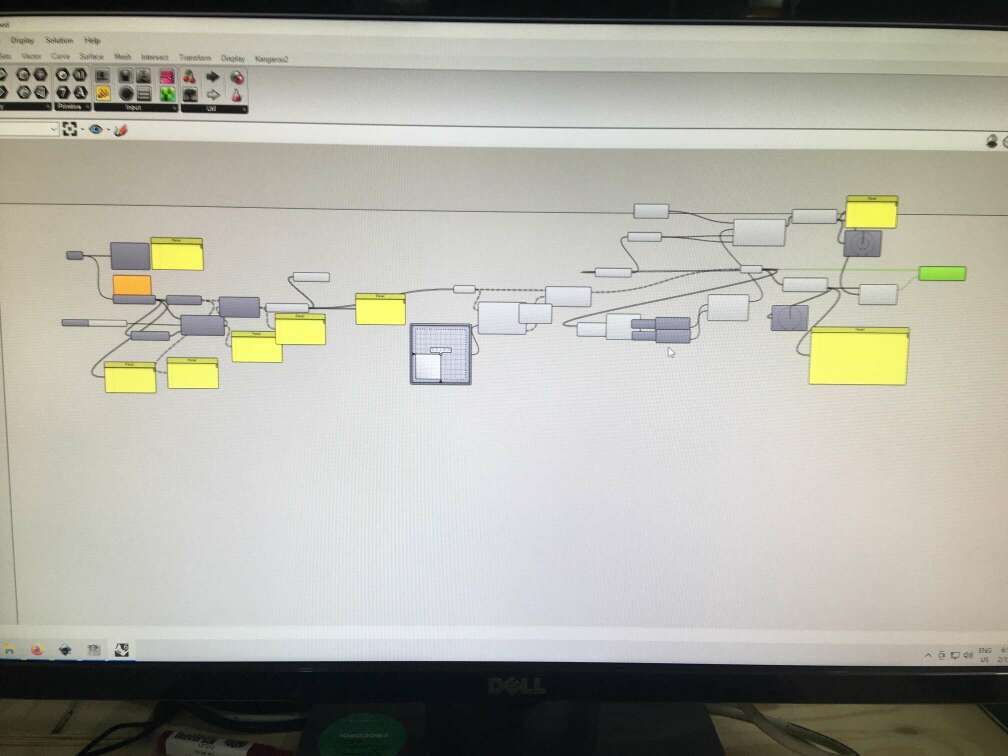
At first i did not wanted to make a really hard geometry for the vilyl cutter but I ended up with a huge grasshopper script that Eduardo Chamorro helped me because it was out of my possiblities. The idea was to make an sphere and unfold the geometry to make it lay in a 2D plane.
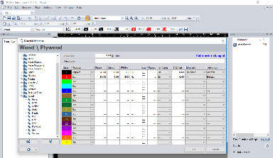
Here is the final sript that we made.
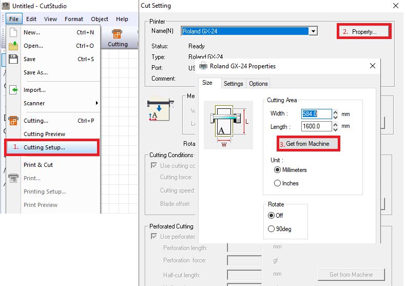
After that I exported the lines in the Adobe Ilustrator (.ai) because the software Cut studio only reads this and some other strange formats, remember that when you open the image to the software you need to import it not no open, if not you are not going to be able to see it.
finaly afer some cuts to try the depht of cut i threw the final cut.
this is the final result.