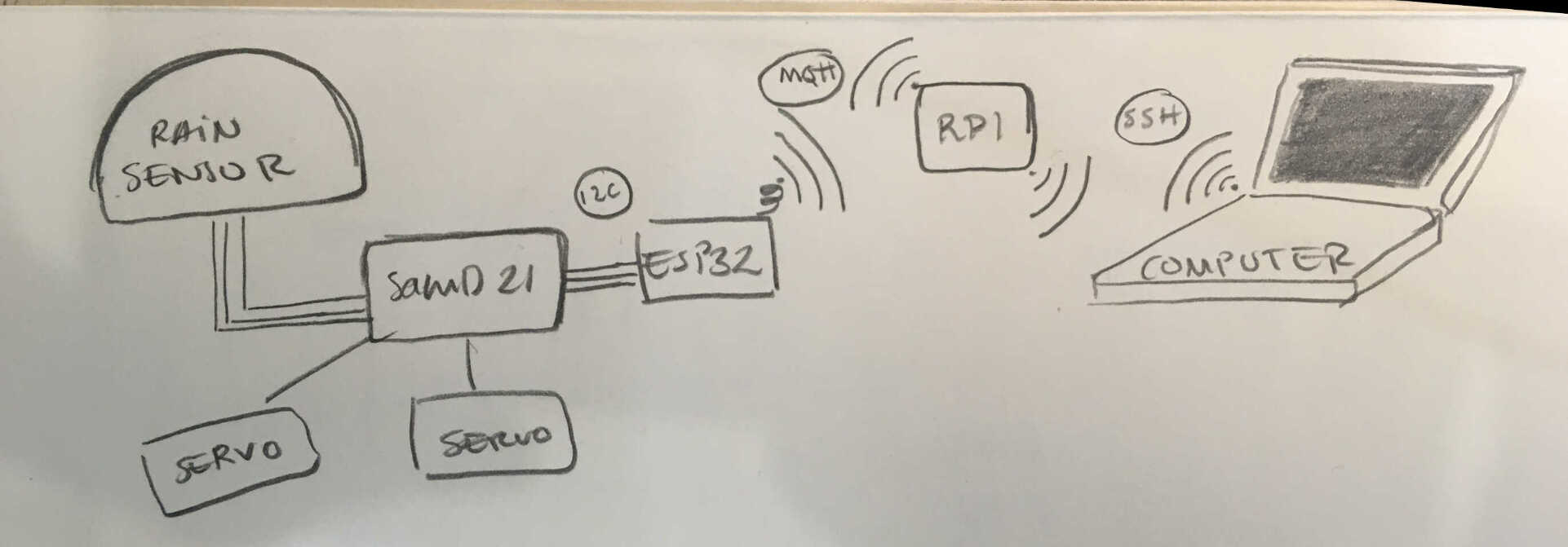
14. Networking and communications
IR SENSOR
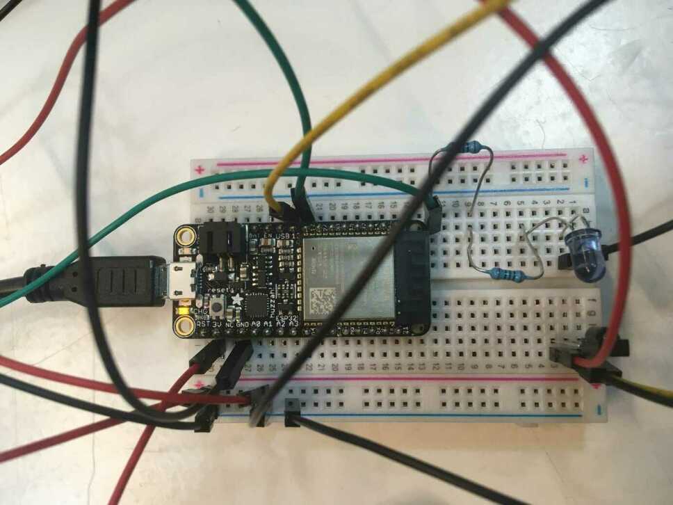
The idea for this week was to make a sistem to talk usiing two PCB, one sending a code using a IR led and the other one reciving this information with an IR sensor.
At first controling the led shoud have been quite straight forward, but it was quite a nightmare sill not working, and I jumped on trying to read the IR sesor, this was just a matter of reading and writing to the serial. Using a remote control of the TV i was capable to read the code that the remot control was sending on each button, see the video ↓↓
int irSensor = 27;


void setup() {
  // put your setup code here, to run once:
  pinMode(irSensor, INPUT);
  Serial.begin(115200);

}

void loop() {

  Serial.println(digitalRead (irSensor));
  delay(100)
SENDING VIA SERIAL
As a second exersise I tried to send the readings of my ranin sensor fron one board to another using the serial. The board I was using to read the sensor was controlled by a SAMD21 which is capable to send data using TX and RX (serial) but the first try was not succsecful, I couldn’t send the data to another board.
I started to try if using two arduino UNO was easyer to check if the code I was using was correct.
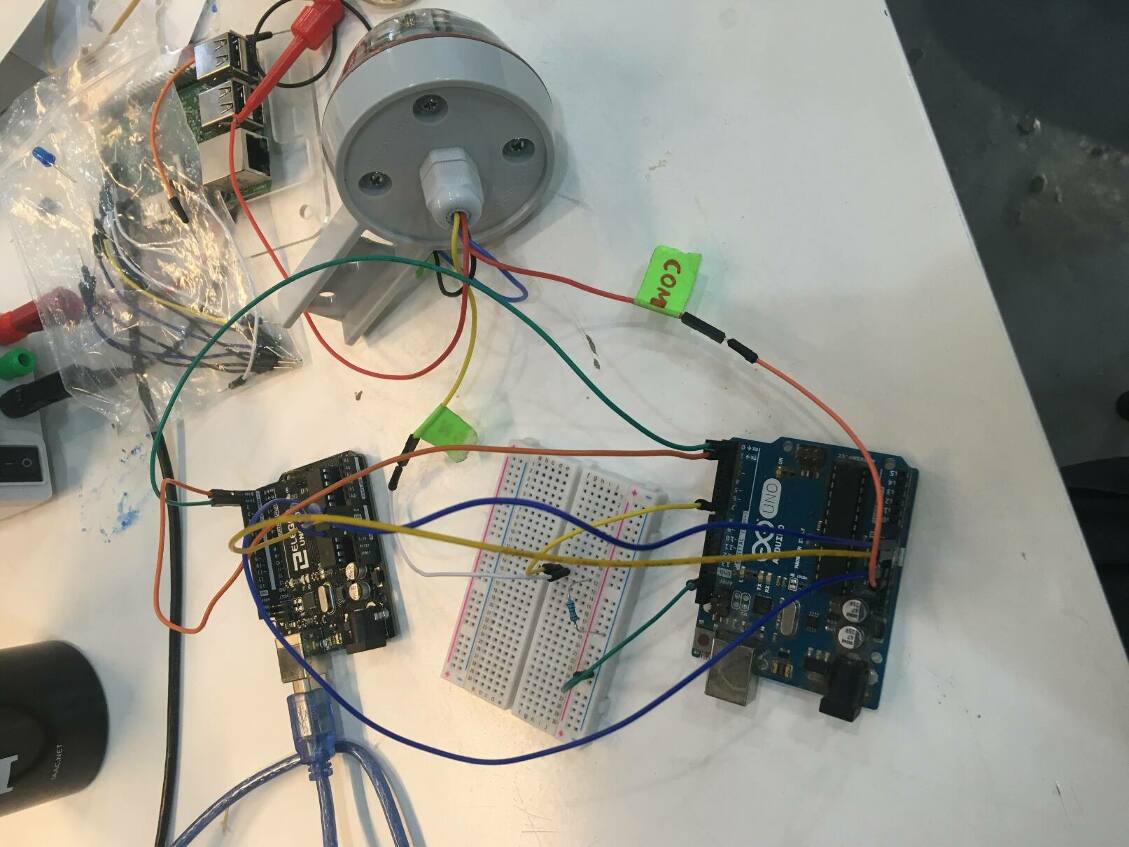
Finaly I was finally able to send the data I was reciving from the sensor from one arduino to the other.
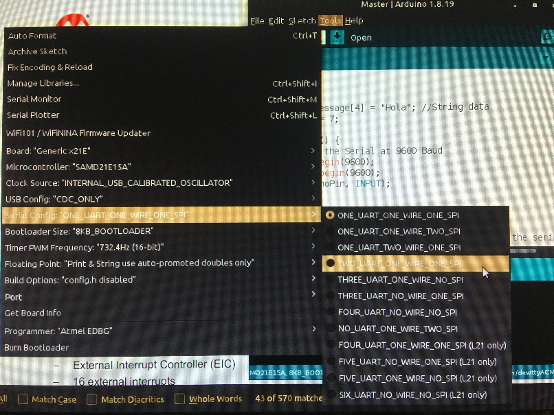
To do the sam with the SAMD21 after fighting with Arduino and the datasheet of the sensor I realized that the issue was really simple, I was missing to change the serial configuration when uploading the code from ‘one_uart’ to ‘two_uart’. finaly it worked!
This is the code of the reader and sender ↓↓
// TX = PA10
// RX = PA11


int noPin = 7;

void setup() {
  // Begin the Serial at 9600 Baud
  Serial.begin(9600);
  Serial1.begin(9600);
  pinMode(noPin, INPUT);
}

void loop() {
  //noPin = digitalRead(noPin);
  Serial1.println(digitalRead(noPin)); //Write the serial data
  //Serial.println(digitalRead(noPin));
  delay(100);
}
This is the code of the reciver ↓↓
void setup() {
  // Begin the Serial at 9600 Baud
  Serial.begin(9600);
}

void loop() {
  //noPin = Serial.read(); //Read the serial data and store in var
  if (Serial.read() == 49) Serial.println(1);
  else (Serial.println(0));

//  Serial.println(Serial.read()); //Print data on Serial Monitor
  while (Serial.available()) Serial.read();
  delay(500);
}
In the reciver (Arduino Uno) I wasn’t reciving a 1 and a 0 and I don’t know why. I was reciving 49 as a 1 and a 0 so I had to make this if (Serial.read() == 49) Serial.println(1); in order to read only one and zero.
I2C
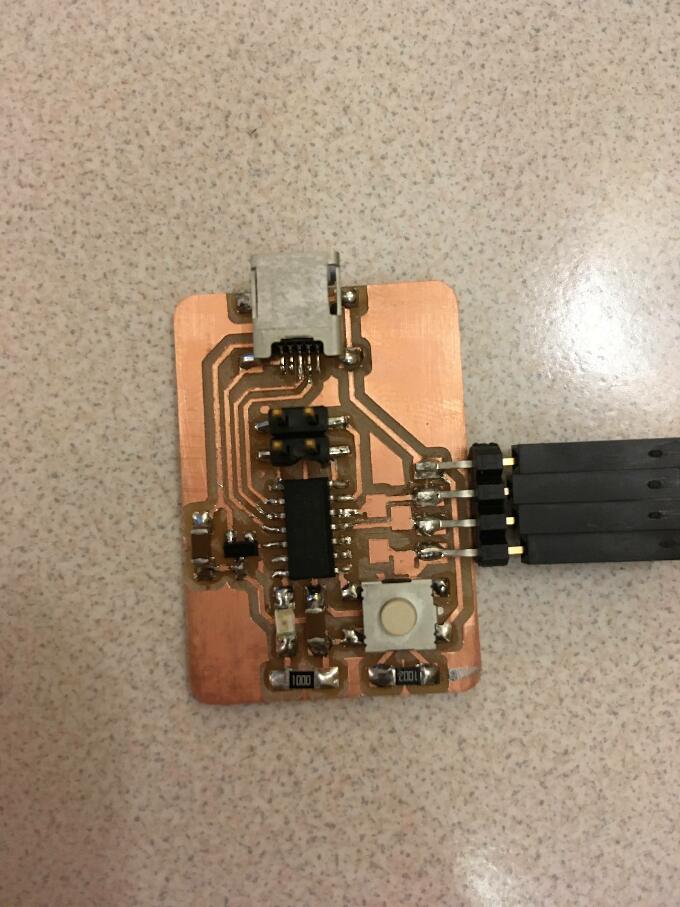
As a third exercise I took two boards made with a SAMD11C14A that exposes some pins:
- GND
- 3.3V
- SCL (serial clock) PA09
- SDA (serial data) PA14
Also includes an LED in PA04 and a button in PA05. The idea is to wire both boards together and with the button of the master board light the LED of the slave board. All using I2C protocol.
The I2C protocol involves using two lines to send and receive data: a serial clock pin (SCL) that the Arduino Controller board pulses at a regular interval, and a serial data pin (SDA) over which data is sent between the two devices.
Connectig both boards GND to GND, SCL to SCL, SDA to SDA and 3.3V to 3,3V we will be able to send information from the master board to the slave board. the slave board could send data back if the master ask fo it.
MASTER ↓↓
#include <Wire.h>

void setup() {

  Wire.begin(8);                // join i2c bus with address #8
  Wire.onRequest(requestEvent); // register event
  pinMode(5, INPUT);  // set button as input at pin 5
  Serial.begin(9600);  // start serial for output
}

void loop() {
  delay(100);
}

// function that executes whenever data is requested by master
// this function is registered as an event, see setup()

void requestEvent() {

  if (digitalRead(5)) {
    Wire.write("0");
  }

  else {
    Wire.write("1");
  }
}
SLAVE ↓↓
#include <Wire.h>

void setup() {
  Wire.begin();        // join i2c bus (address optional for master)
  Serial.begin(9600);  // start serial for output
  pinMode(4, OUTPUT);  // set led as output at pin 4
}

void loop() {

  Wire.requestFrom(8, 1);    // request 1 byte from peripheral device #8
  while (Wire.available()) { // peripheral may send less than requested
    char c = Wire.read(); // receive a byte as character
    Serial.print(c);         // print the character

    if (c == '1'){
      digitalWrite(4, HIGH); // light the LED when reciving 1
    }

    else{
      digitalWrite(4, LOW); // turning off the LED
    }
  }

  delay(500);
}
In this case we are not sending a nubmer as HIGH or LOW instead we are sending 1 and 0 as a text to we can ‘char’ the wireRead and make a condition with it, I could not figure a better way. For sure the one I’m using is not the best one but is the one that worked! (Thank you JEP!!)
RASPBERRY PI AND GRAFANA
Finaly I started thinking in my final project that would be nice to recive some notifications from the machine. And I found some documentation on how to get data and make some nice visualitzation using grafana but I didn’t had time to continue exploring this topics.
would be nice to explore this later on.