9. Embedded programming
For this week assignment I made a board using the SAMD11C14A with one button two programable LEDs and one control LED to know if the PCB is reciving power.

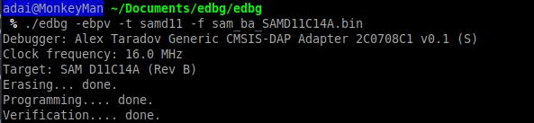
Once the board is cuted and all the components are soldered is time to burn the bootloader, I am going to use edbd to do it. Once we have loaded the bootloader now we are able to program it using arduino.
Arduino will recognise the board in a port, just select the port and select the same board in the board manager, I am using the fab SAM core for arduino.

const int buttonPin = 4;     // the number of the pushbutton pin
const int ledPin =  14;      // the number of the LED pin
const int ledPin1 =  5;
boolean currentState = false;
boolean lastState = false;

void setup() {
  // initialize the LED pin as an output:
  pinMode(ledPin, OUTPUT);
  pinMode(ledPin1, OUTPUT);

  // initialize the pushbutton pin as an input:
  pinMode(buttonPin, INPUT);
}

void loop() {
  // read the state of the pushbutton value:
  if ((digitalRead(buttonPin) == 0) && (lastState == currentState)) {
    currentState = !currentState;
    if (currentState == true) {
      digitalWrite(ledPin, HIGH);
      digitalWrite(ledPin1, HIGH);
    }
    else {
      digitalWrite(ledPin, LOW);
      digitalWrite(ledPin1, LOW);
    }
  }
  else if (digitalRead(buttonPin) == 1) {
    lastState = currentState;
  }
  delay(0);
}
SAM D11C 14A
A new generation of Atmel microcontrollers with SAMDs. A low-power, high-performance ARM® Cortex®-M0 + based flash microcontroller and with a full-speed USB device.
- 14 pin package.
- Internal and external clock options with 48MHDigital Frequency Locked Loop (DFLL48M) and 48MHto 96MHFractional.
- 16 KB Flash Memory.
- 256 B EEPROM.
- 4 KB SRAM.
- Maximum voltage: 3.63 V; minimum voltage: 1.62
After looking at the basic features, you will find the pinning of the microcontroller. More information in this link.
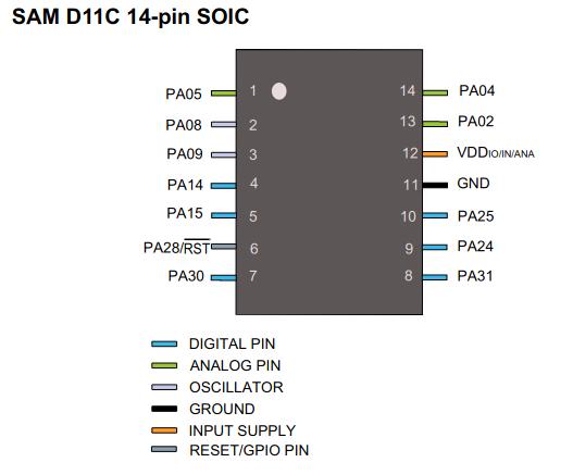
- VDD: Supply voltage.
- GND: Ground.
- Digital pins: PA02, PA04, PA05, PA08, PA09, PA14, PA15, PA31.
- Analog pins: PA02, PA04, PA05, PA14, PA15.
- USB pins: PA24, PA25.
All I/O pins can be configured with internal pull up or pull down resistance.