Road to the Final Project
First concept
My final project is really far from its final form. There’s so much to be thought and valuated…
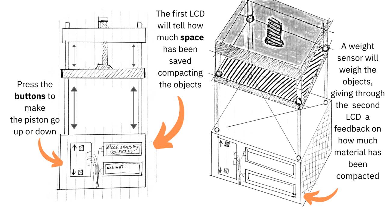
Let’s say that the whole idea floats around the concept of an automatic hydraulic press that gives a feedback to its users on how much space has been saved through the process and how much grams of material have been compacted.
My objective is to help people save space in their houses compacting recyclable trash. I would like to create something that can press cans and plastic objects. Old people and people with arm disabilities could be able to recycle without any effort.
The first thing that concerns me is the structural issue: given the list of available materials for Fab Academy students, I could struggle to find something strong enough to bare the pressure made by the engine. The latter concerns me for its price, given the budget available for each student.
One possible approach for the project would be to create a scaled prototype, so that with the right calculations, the whole machine could be enlarged in order to compact bigger things.
Furthermore, the prototype could be re-elaborated out of the academy with more resistant materials.
This is the initial sketch:
Useful links for project’s concept
- mistrymaketool
- Hydraulic letterpress
- 12V Mini Electronic Press Machine
- Precious Plastic
- HomeMadeTools
- How to control an hydraulic press with Arduino
- Homemade hydraulic press
UPDATE Week 02
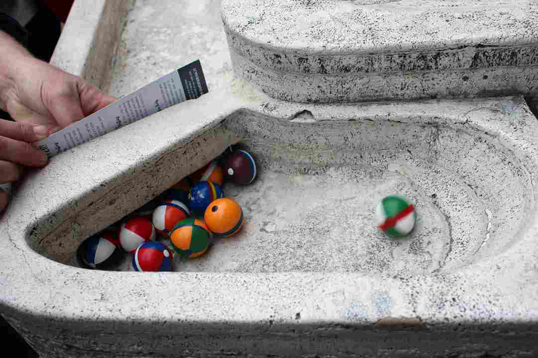
The Hydraulic press did not convince me for the structural possible future issues. While I was reaching the Fab Lab for week two’s global lecture, I stumbled upon one of those good old memories of when I was a young child. Spread in some gardens in Siena it is possible to find marble tracks where children brought their marbles and run against each other. It is a cultural heritage for those who were born in Siena and I really would like to apply the process of retrofitting to it.
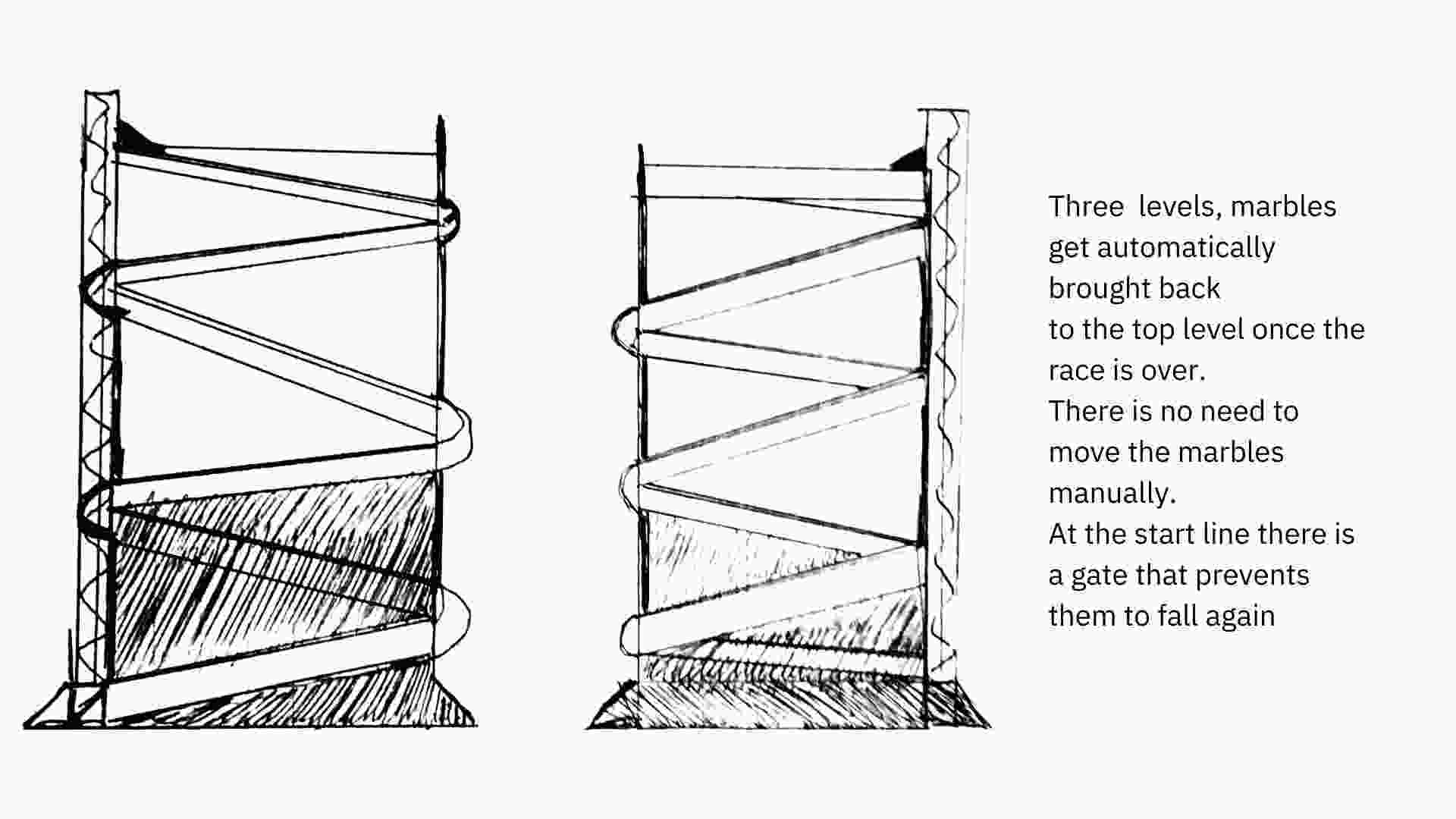
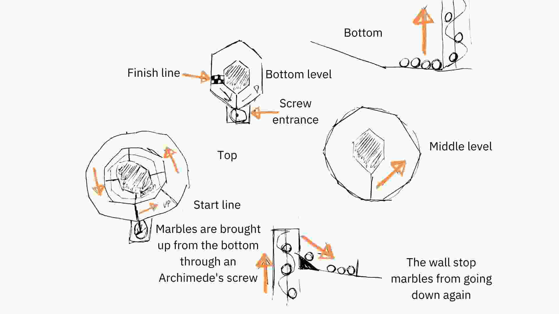
The marble track is going to have 3 sections. On top of it there’s going to be an automatic gate that prevents the marbles from accidentally following gravity rules too early. Once the marbles start rolling to the end, they have to face a spyral-shaped track. At the end of it there is the finish line with a sensor that outputs the race result, then all the marbles are brought back to the top through a screw. The marbles have to be created as well, in order to put a unique ID into each of them, so that the sensor at the end cannot misread the result of the race.
This is the sketch of the project:
I also made a 3D model during week 2, you can check it clicking here.
Electronics
Eagle
While the assembly process was going on, I began designing the PCB. The objective was to obtain a main board with all the components on it, without splitting the components on two separate boards with two microcontrollers. Then I had to create a tiny board with two switches on it in order to control the servomotors remotely.
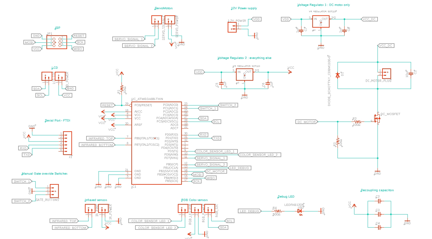
On the main board I placed:
- 1 ATMEGA328p
- 1 ISP 3x2 connector
- 1 FTDI 6x1 vertical connector
- 1 3x1 vertical connector
- 11 terminal blocks
- 2 voltage regulators (from 12V to 5V)
- 1 mosfet
- 1 green LED
- 2 10KΩ resistors
- 1 500Ω resistor
- 1 100Ω resistor
- 1 zener diode (4,7V)
- 7 1uF capacitor
- 1 10uF capacitor
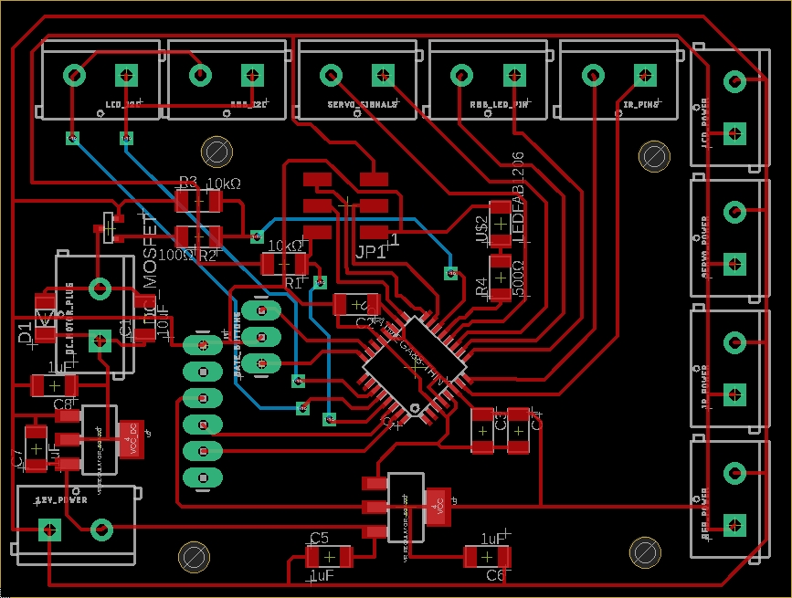
This is its schematic (downloadable here):
This is its routing (downloadable here):
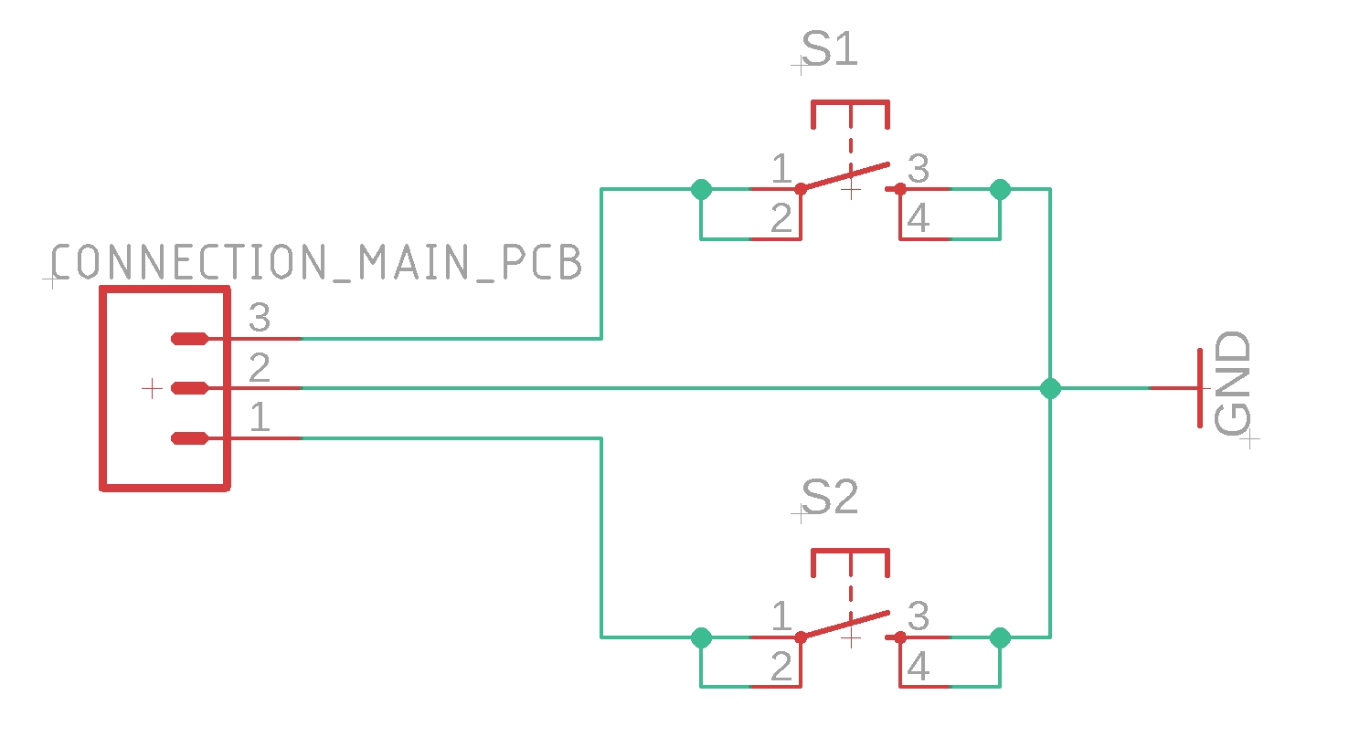
While on the tiny board I placed:
- 1 3x1 vertical connector
- 2 switches
This is its schematic (downloadable here):
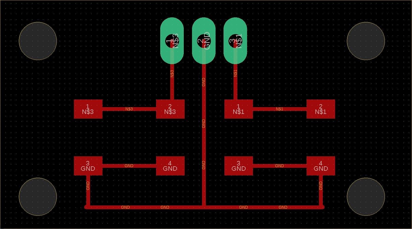
This is its routing (downloadable here):
Milling
From the beginning of the Fab Academy I never got along with the Roland SRM-20. Neither this week the trend changed: I had to mill the PCB three times.
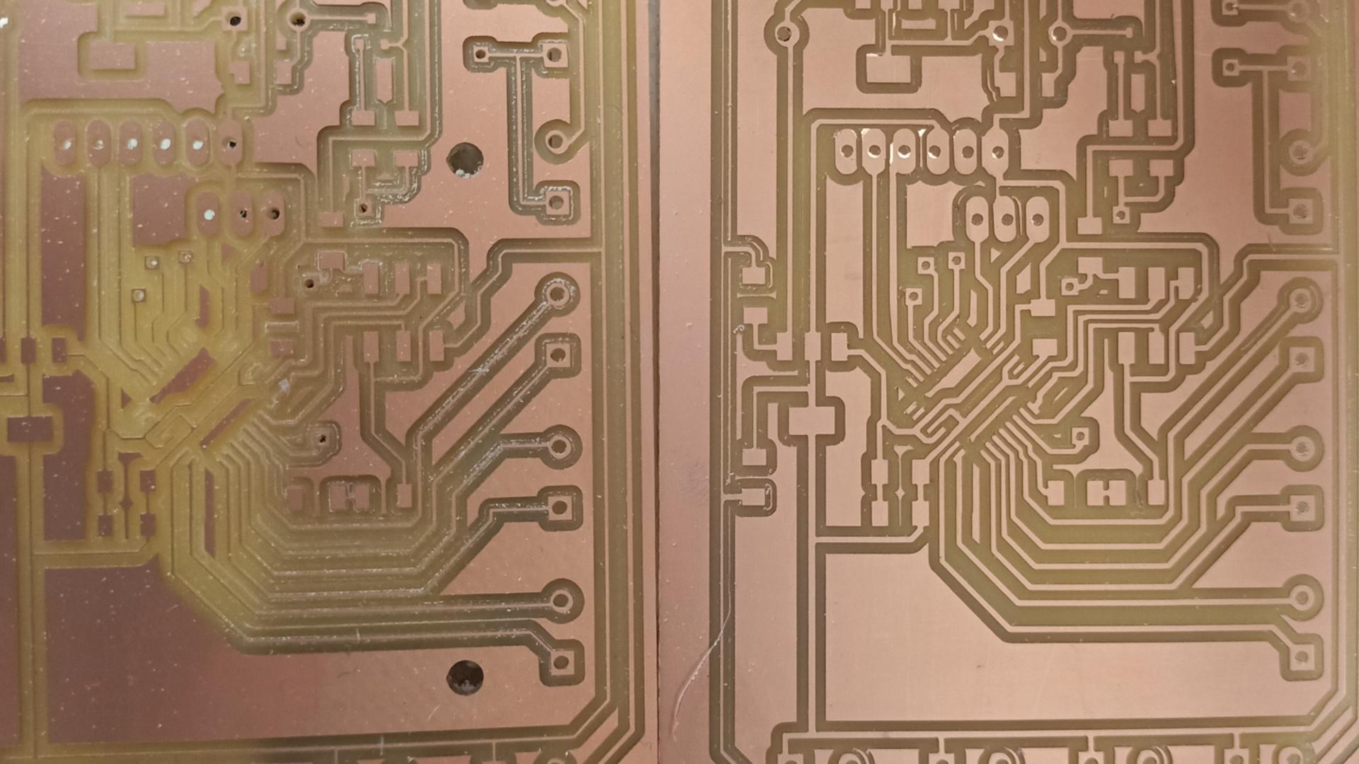
As you can see from the picture above, I had two different issues. The first is png related, I made some mistakes while creating the png for the milling machine, resulting in too thin routes. The second attempt failed because the board moved while I was milling, so the holes and some routes ended up unaligned.
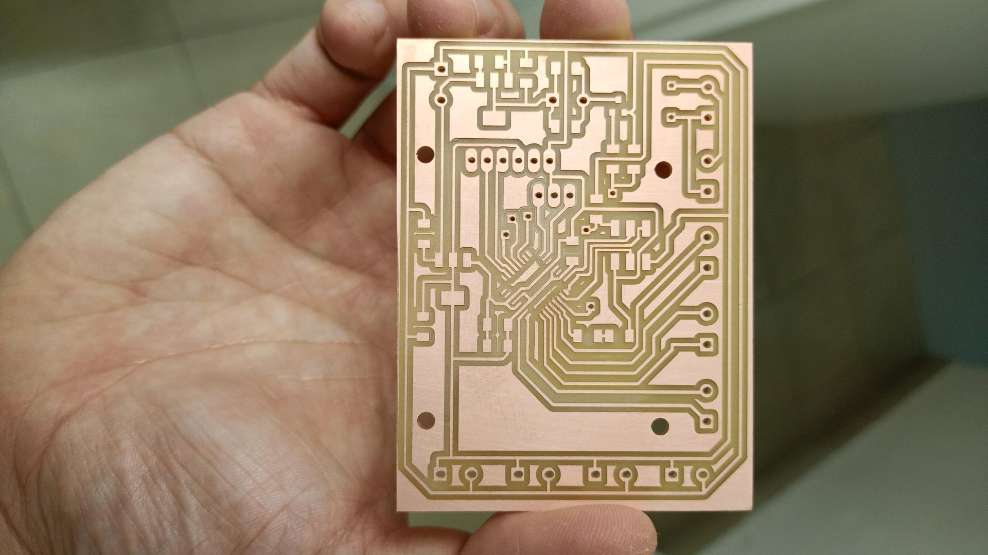
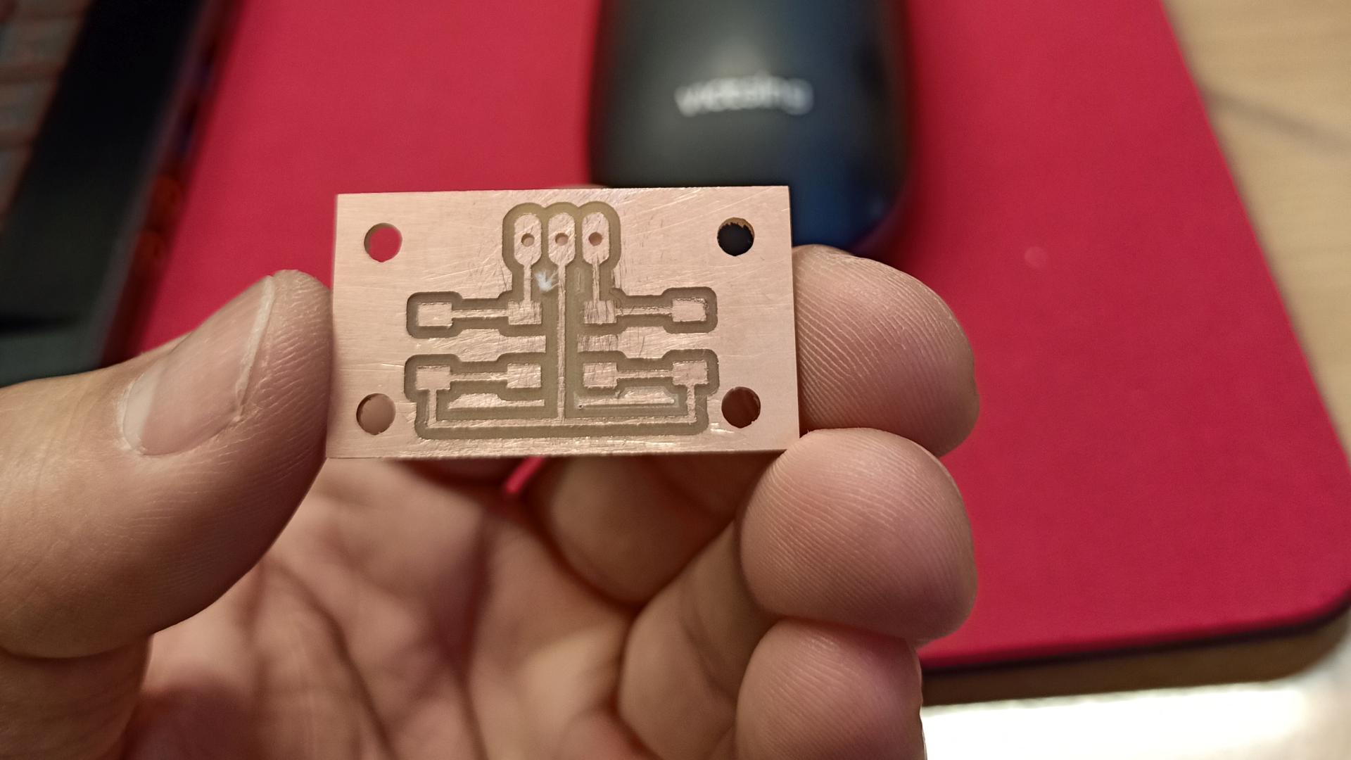
The third attempt has been successful, here’s how the board looks after it has been cleaned:
This is how the tiny switch board looks like:
Soldering
Then I moved on and I soldered both boards. The ATMEGA328 has been quite difficult, given the high number of pins and its reduced size. I had to create some routes from the bottom of the board, then I soldered them to the via that led back to the top level.
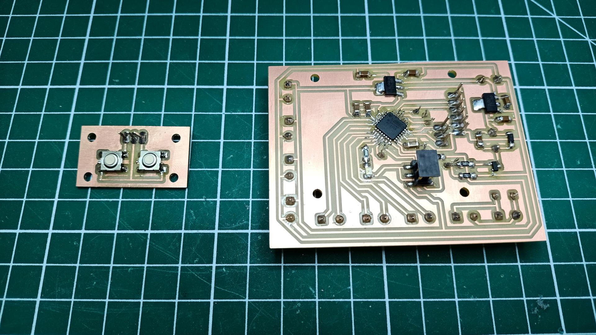
Once all the wires were on position, I glued them to the board on the bottom level, in order to secure their position and avoid any possible damage to the inner wire.
Programming
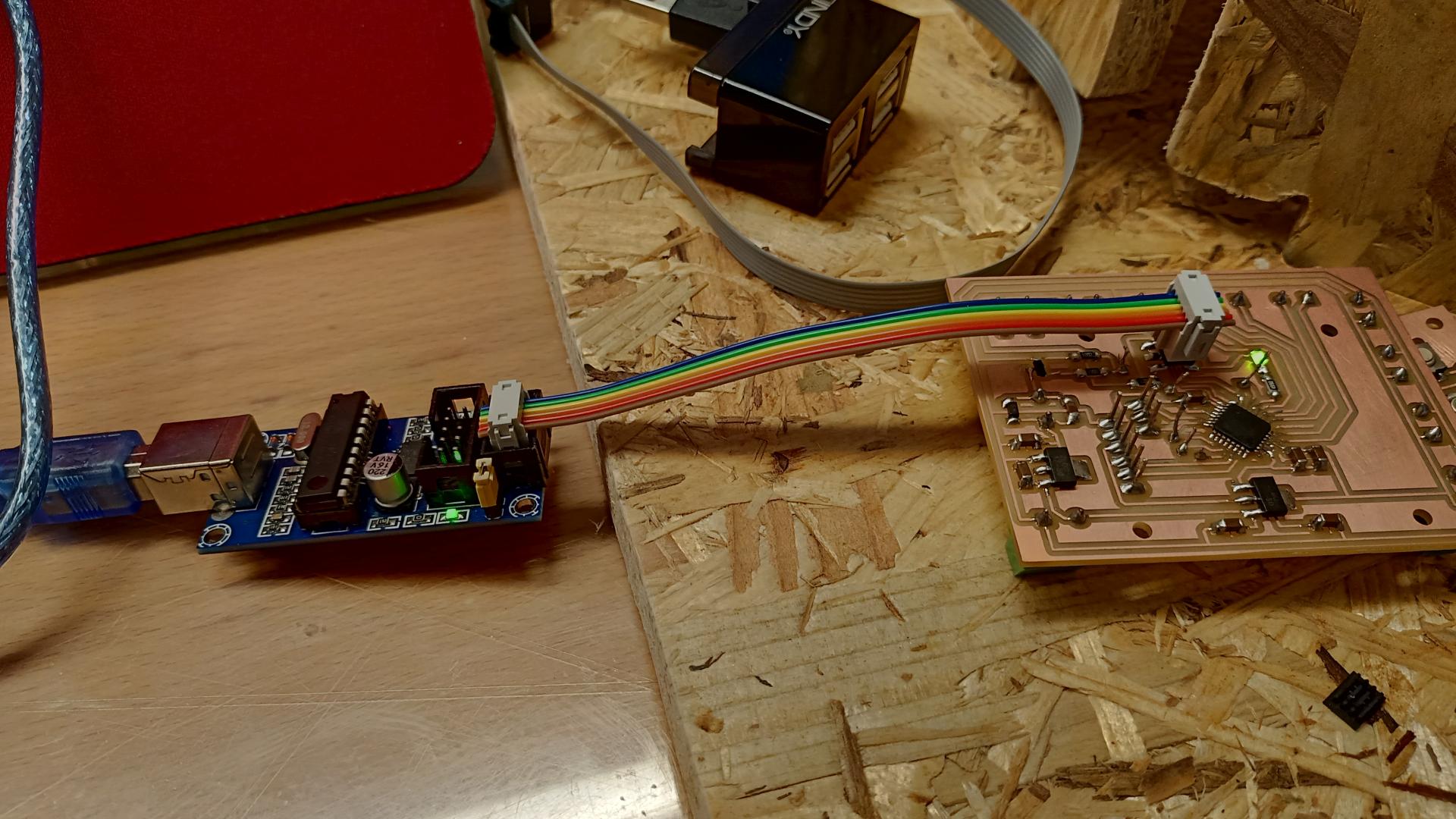
In order to be sure that I did not burn my microcontroller during the soldering process, I decided to try to blink the debug LED I soldered on the board.
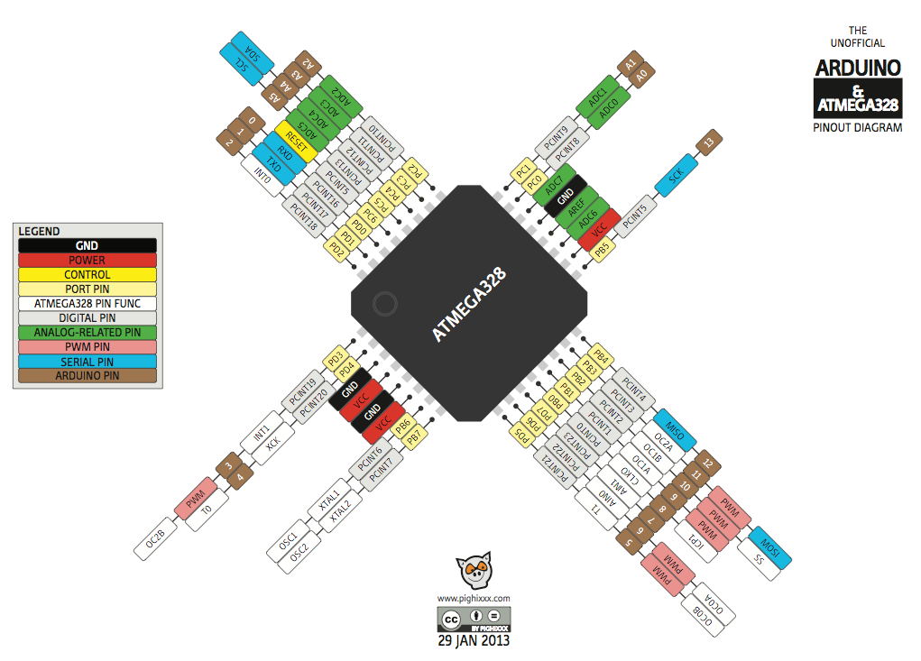
I looked for the Arduino pinout for this board, and here it is:
This is the super basic code I wrote and compiled with the Arduino IDE:
void setup() {
pinMode(9,OUTPUT);
digitalWrite(9,LOW);
}

void loop() {
 digitalWrite(9,HIGH);
}
The LED blinked immediately! The microcontroller is ready to be programmed with longer codes…
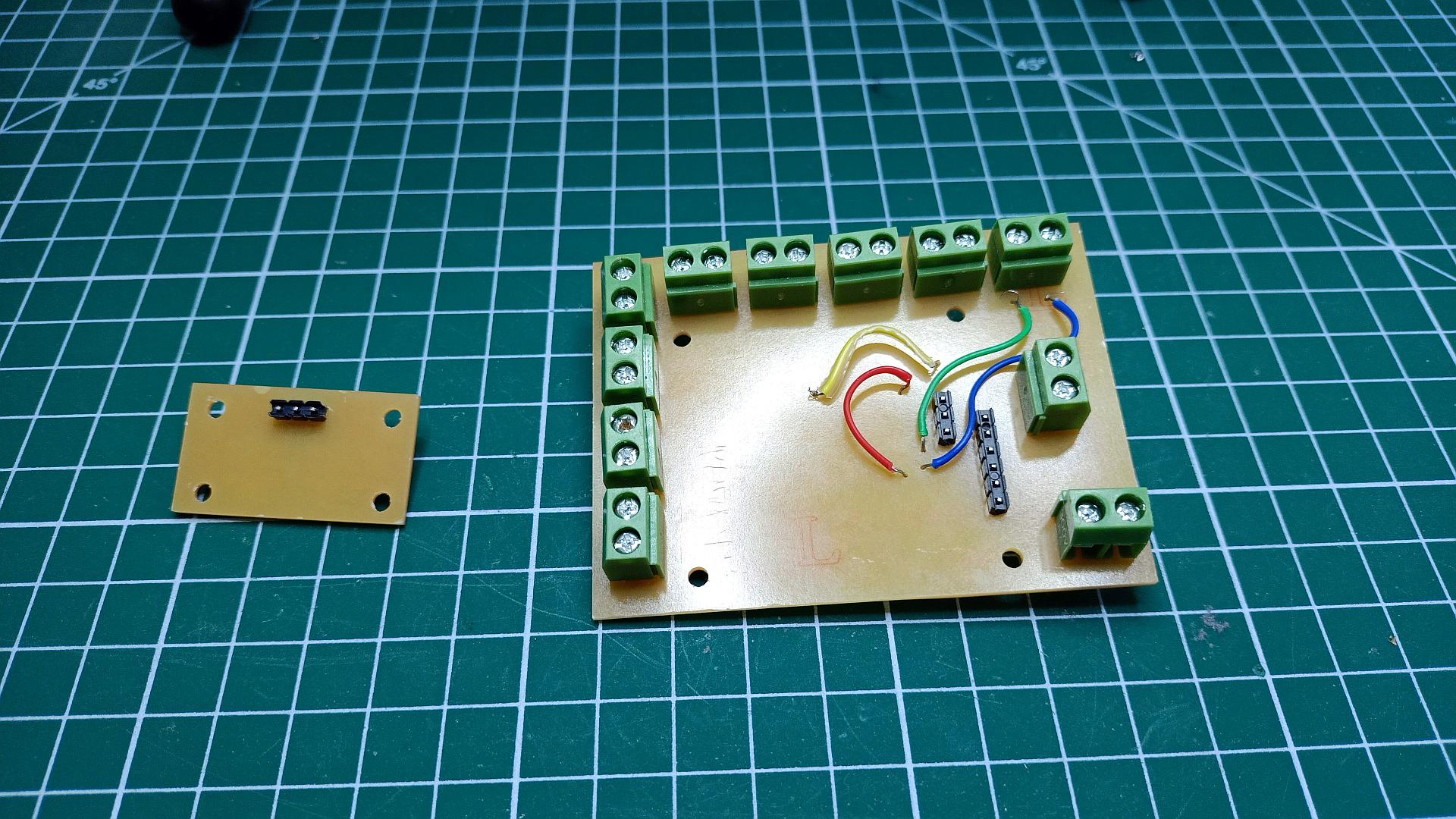
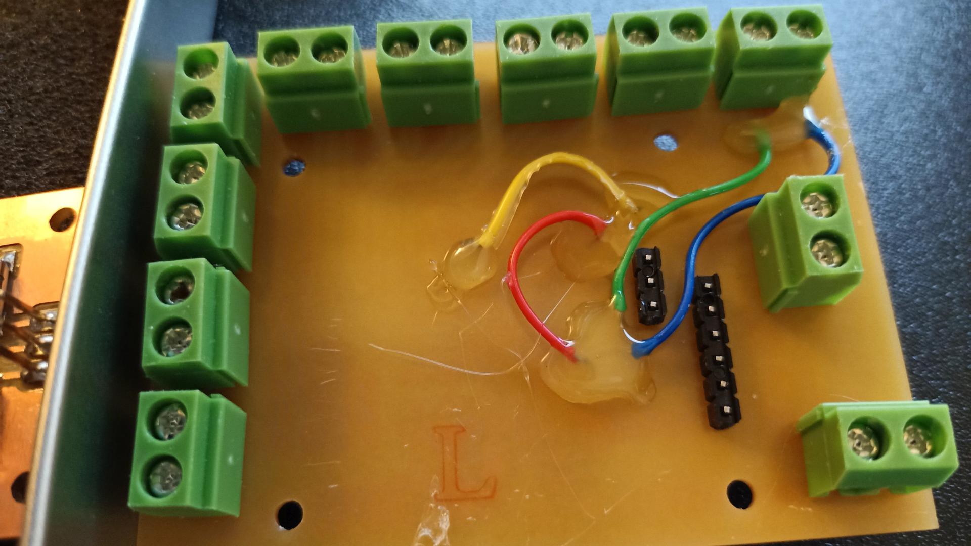
Wiring
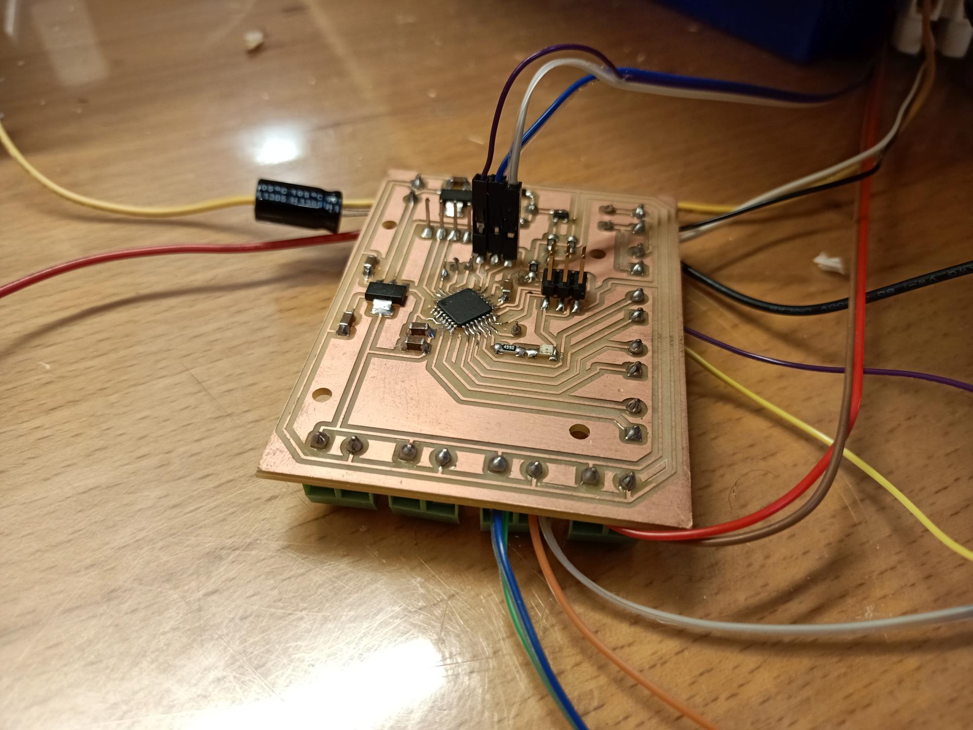
I tried all the components first with short wires really close to the PCB. Once I realized everything worked properly, I prepared longer wires so that I could easily connect all of them to the board below the track base. This is how the board looks once all the wires are in place:
Trying the LCD and the switches
Once I turned on the machine, everything worked perfectly. The LCD says what the code wants it to say, the buttons let the machine do what the code wants it to do.
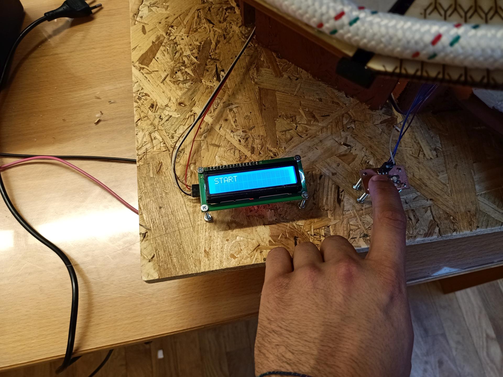
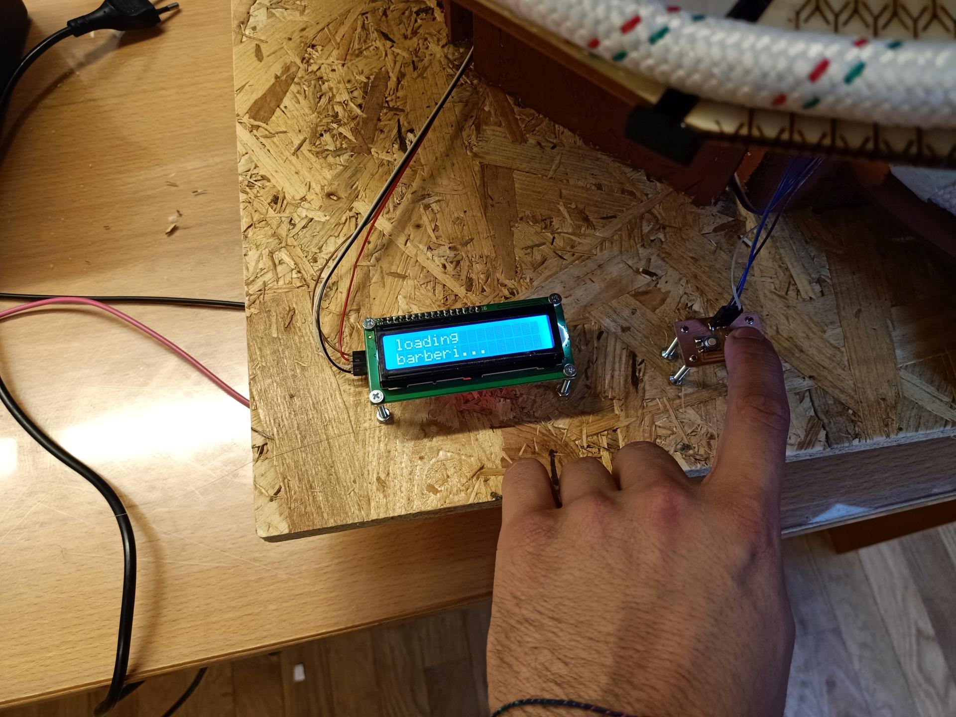
This is how everything behaves:
Mechanical design and assembly
UPDATE Week 15
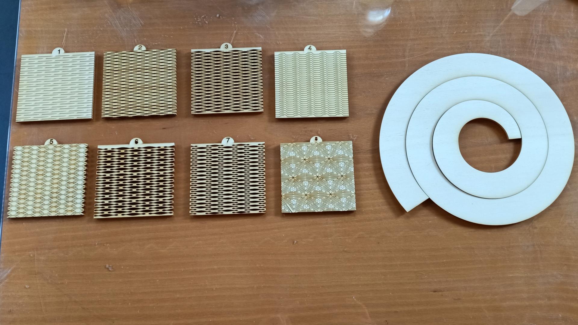
I started preparing the spiral where the marbles are meant to run downwards. My idea is to obtain a single spiral from a piece of plywood. So I prepared a dxf file on fusion with a spiral and then I used Illustrator in order to work with the Laser cutter machine. The first spiral I made is smaller than the one I want to use for my project, but somehow I had to start prototyping.
A way to grant me flexibility is cutting the wood using a pattern all along the surface. The laser cutter machine company has a downloadable file with 8 patterns. I tried all of them and now I think I have found the pattern that works as a compromise between strength and flexibility.
Here’s what I made as a first prototype:
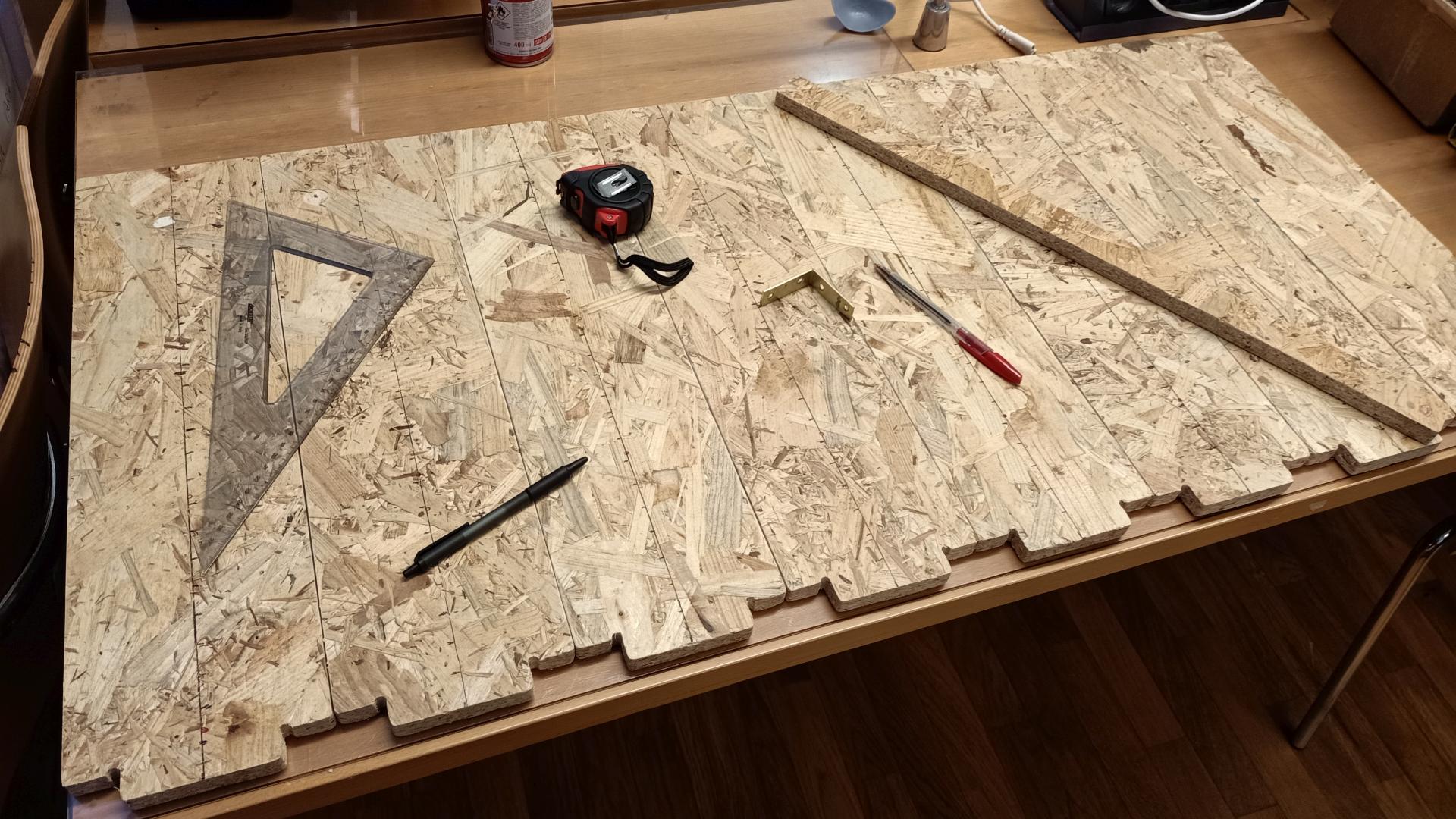
UPDATE Weeks 16 and 17
The Carpentry PC can’t properly elaborate such complex files as the one I needed for a large flexible spiral. So I had to change the track’s shape to something polygonal.
I started designing it on Fusion360.
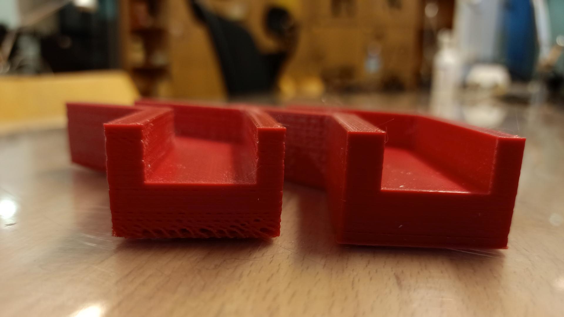
Here’s what I made as a first prototype:
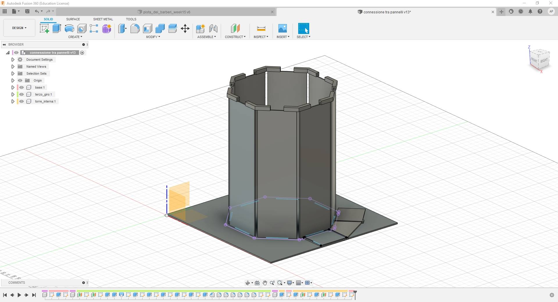
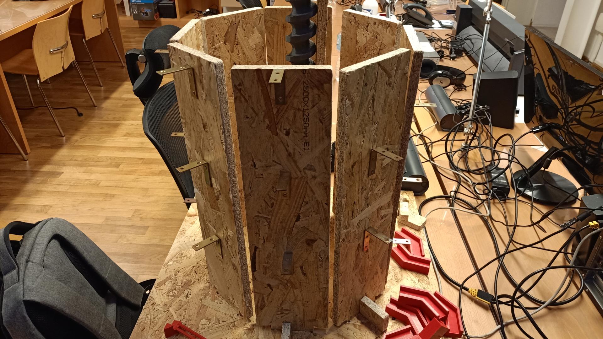
My intention is to obtain a octagonal structure where each straight piece of wood has a 20mm offset from both below and above wood piece. These pieces are going to be connected with each other with something inclined, more or less flexible. First I will put 25 straight pieces all around the octagonal shape I designed and cut.
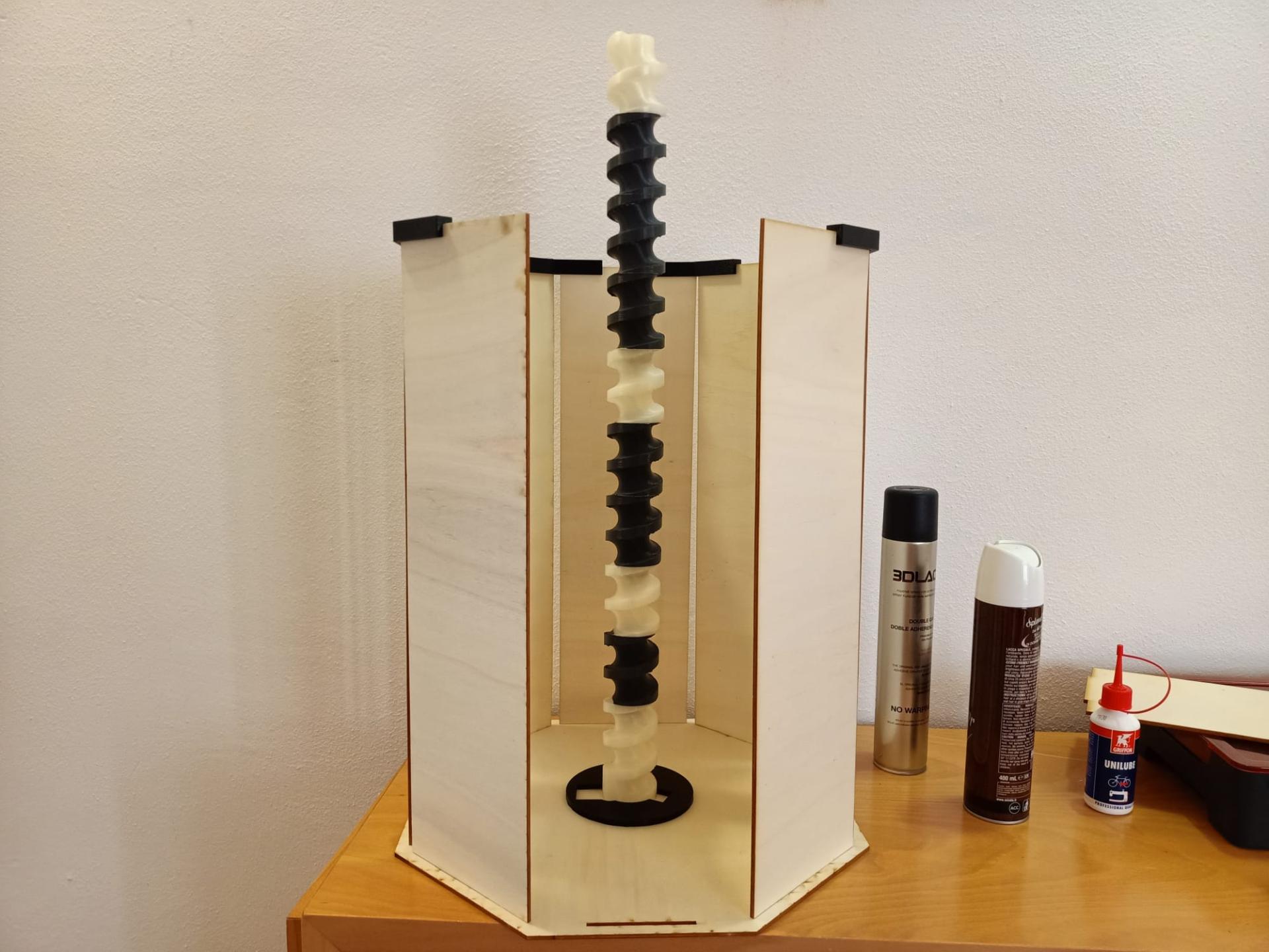
The spiral you see on the middle of the octagon is a working marble lift I found here. This model doesn’t fit with my marbles, so I made a larger version of it. The spiral you see above is made of ten pieces, all of them are made of PLA. I printed them with both Ultimaker 2+ and Ultimaker 3. I still have to create a perimetrical structure that allows me to raise the marbles to the top, but some attempts for a few centimeters worked fine, so the situation looks promising.
UPDATE Week 18
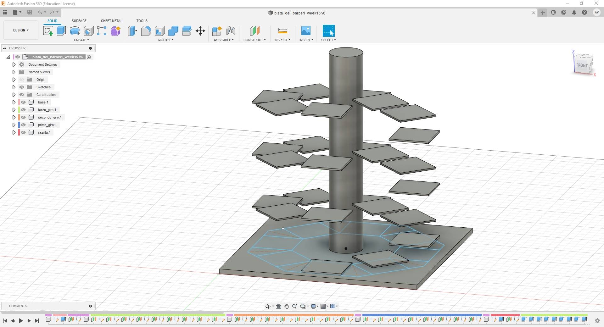
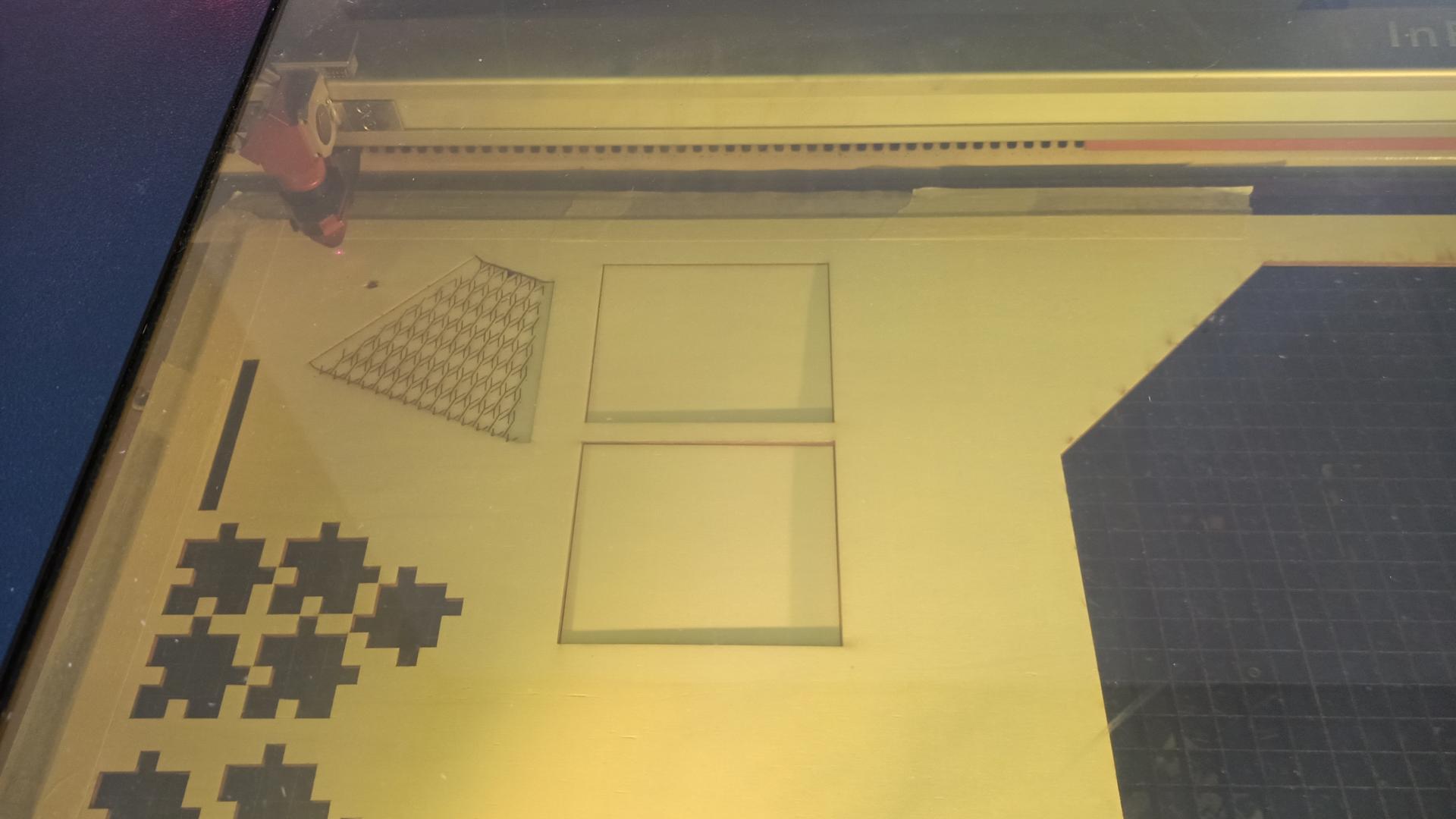
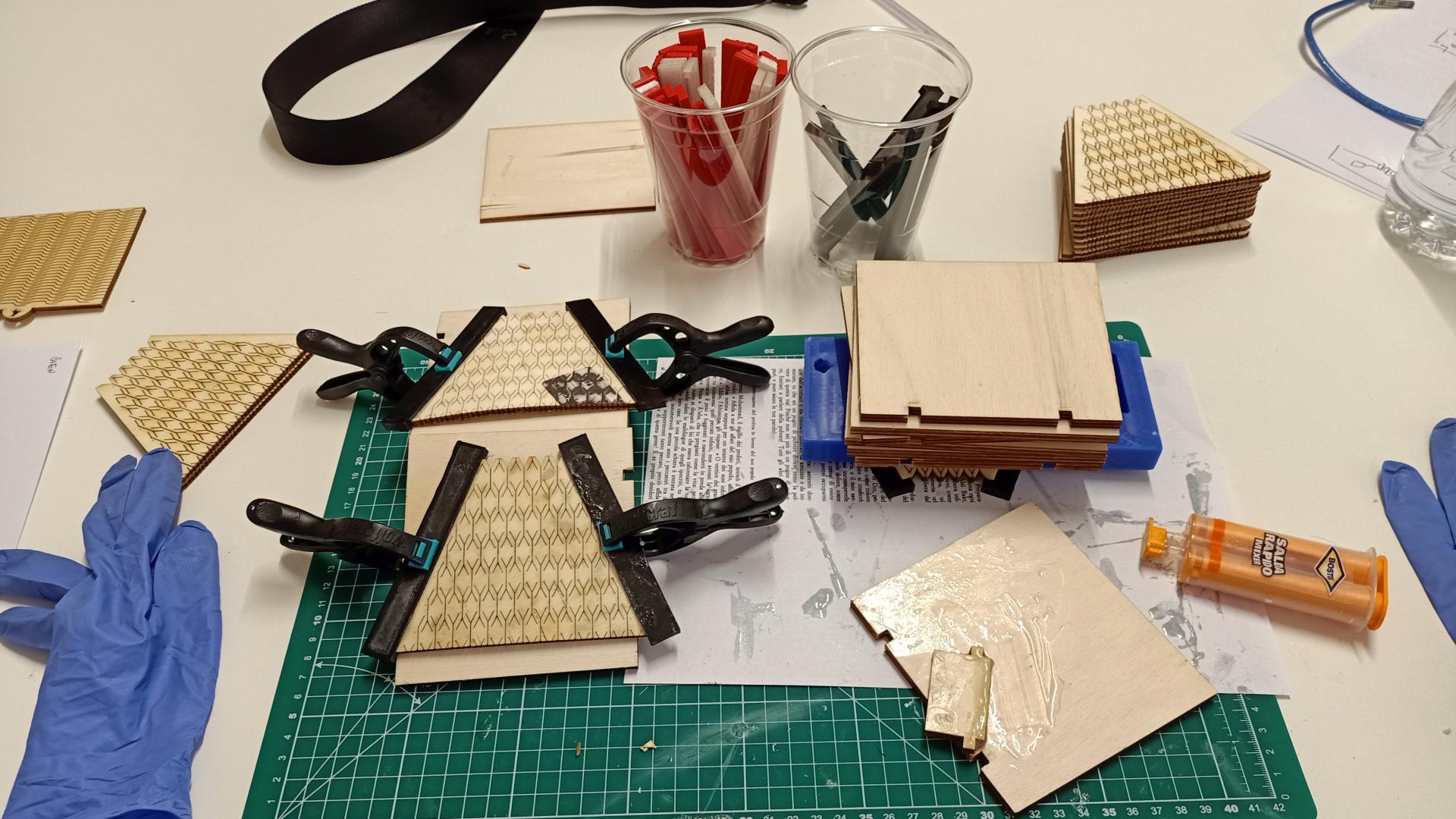
I moved on with the design of the structure, more specifically the marble track. I wanted to obtain the spiral effect with 3 complete revolutions around the central octagonal tower. The track is going to be made of 25 horizontal plain pieces of plywood. Between each of them there is going to be a 20mm offset, going from 0 to 500mm to the top. I had to create a flexible piece of wood between each of these faces, so that I could connect them moving up 20mm from the previous face. I took two sketches from Fusion360 and tried to laser cut them. Of course I had also to create a piece that could connect all the pieces together, something thin but still trustworthy.
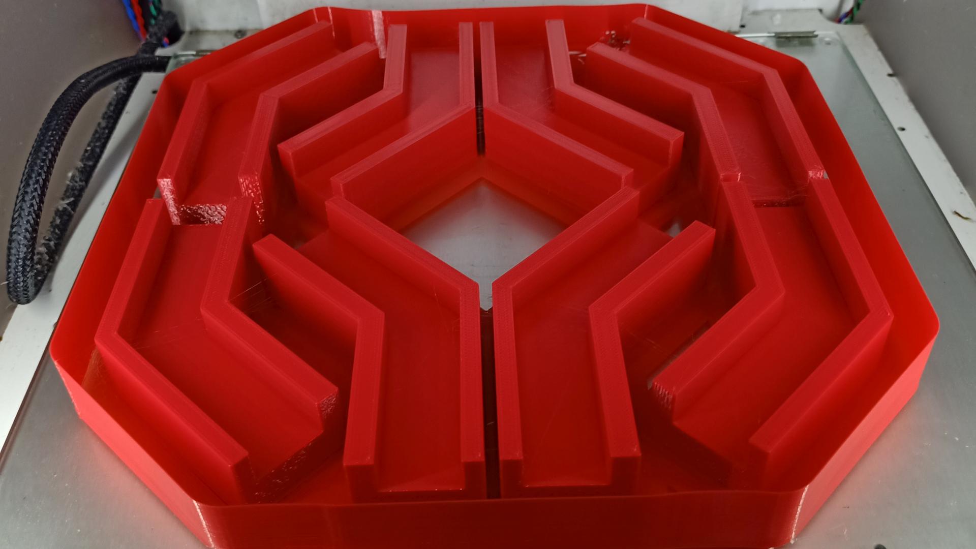
Here’s the 3D model I made:
Then I made the first attempt with this structure:
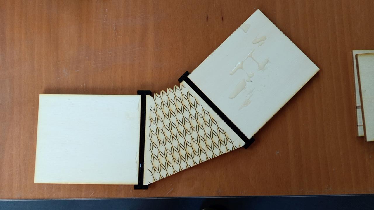
And this is how it moves:
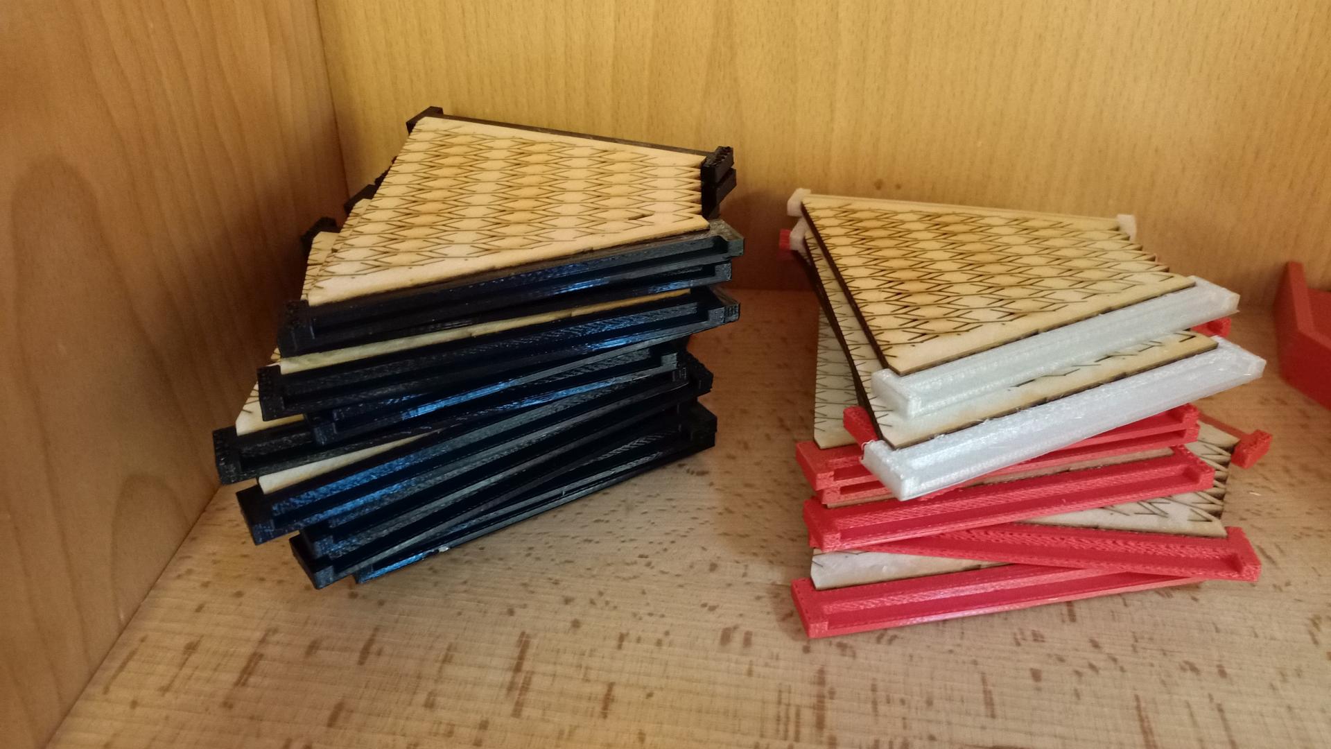
So I decided to go on with this setting and I cut all the other pieces I needed.
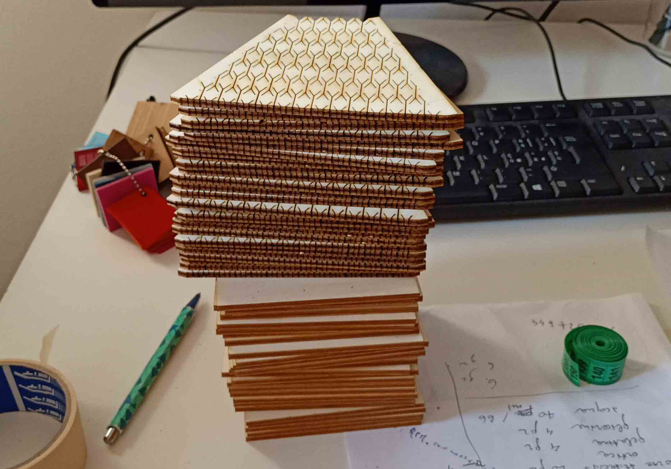
I will have to glue together the flexible piece with the 3D printed pieces, then I will place all the horizontal panel all along the vertical tower thanks to L shaped metal supports. Then I will put all the pieces together with more glue and 4 clamps.
Next thing to do in the following days:
- cut new pieces for the vertical octagonal tower with ticker wood, since the thin 4mm plywood bends if its height is 300mm or more.
- design and create the electronics.
- put all the pieces together.
UPDATE Week 19
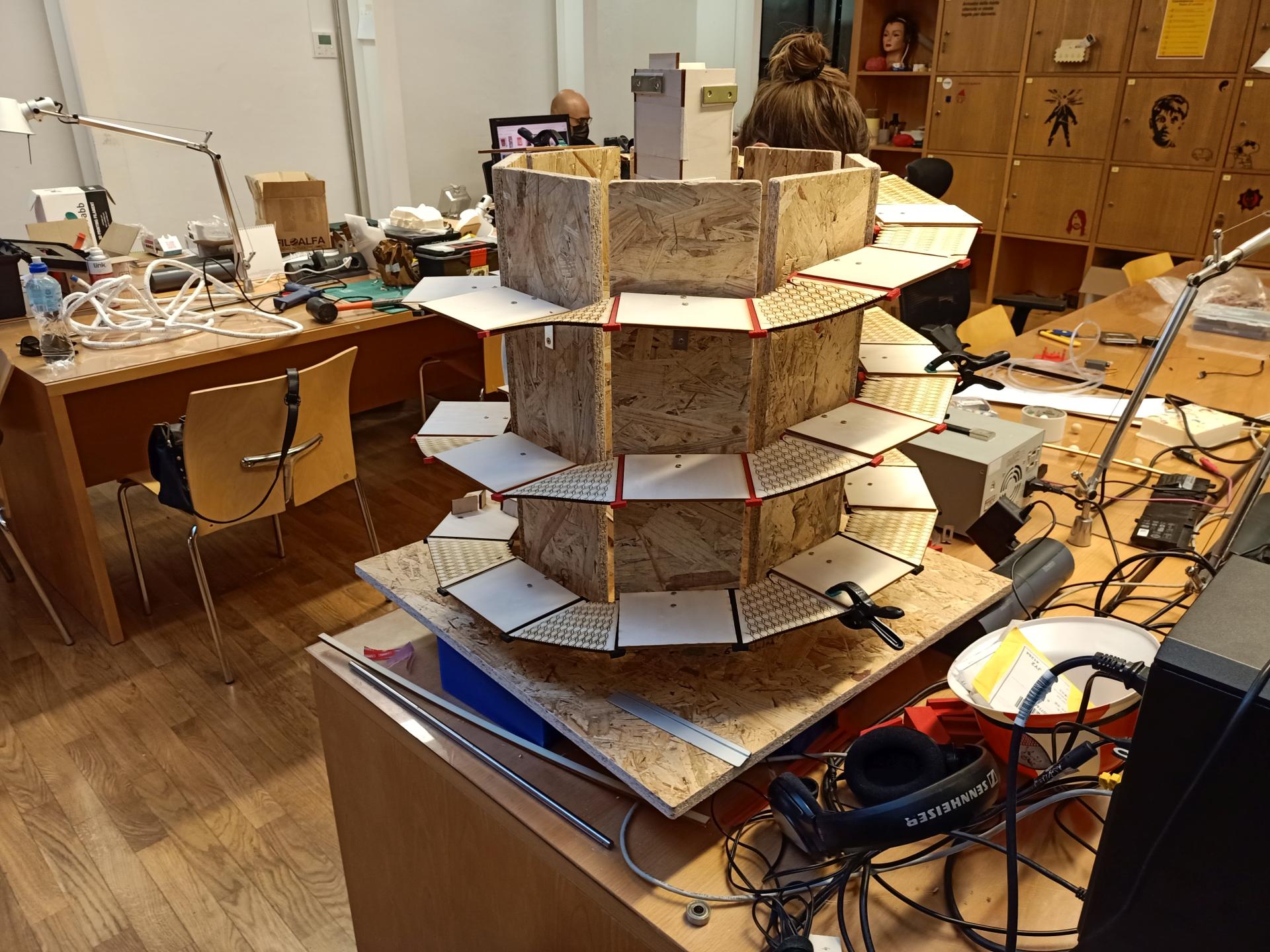
It is finally time to assemble the central octagonal tower with the new thicker pieces. Before placing them vertically I decided to mark and drill the holes for the metal supports that will sustain the marble track.
Once all the metal supports are on place, I installed all the straight parts of the marble track. I used M3 screws and double sided tape. This is how it looks:

Then I moved on with the building process: it is time to glue the flexible parts with their 3D printed supports.
After a few hours I glued all the flexible pieces, ready to be assembled on the track.
I also needed to redesign and print new supports for the upper side of the octagonal tower. Unfortunately I had to change the PLA filament. This specific spool gave me some under-extrusion issues. I had to change most of the settings: higher temperature, fan speed off and draft shield. Here’s a comparison between the first print with the old settings (on the left, even if it may be obvious) and the unorthodox print with the new settings:
Then I made a new set of supports:
UPDATE week20
I moved on and the next, if not the most important assembly step, is the marble lift at the center of the base. I kept on working on the Fusion360 file I previously made for the octagonal tower and then I obtained 2 dxf files from it. This is how the model looks like on Fusion360:

This is how the tower behaves:
Then I needed to focus on the finish line of the marble track. I had to find a way to connect the marble track to the spiral. This is the 3D model I updated from the previous versions with the new section.
So I laser cut the DXF files and then I placed all the pieces together. Everything looks surprisingly well at the first attempt.
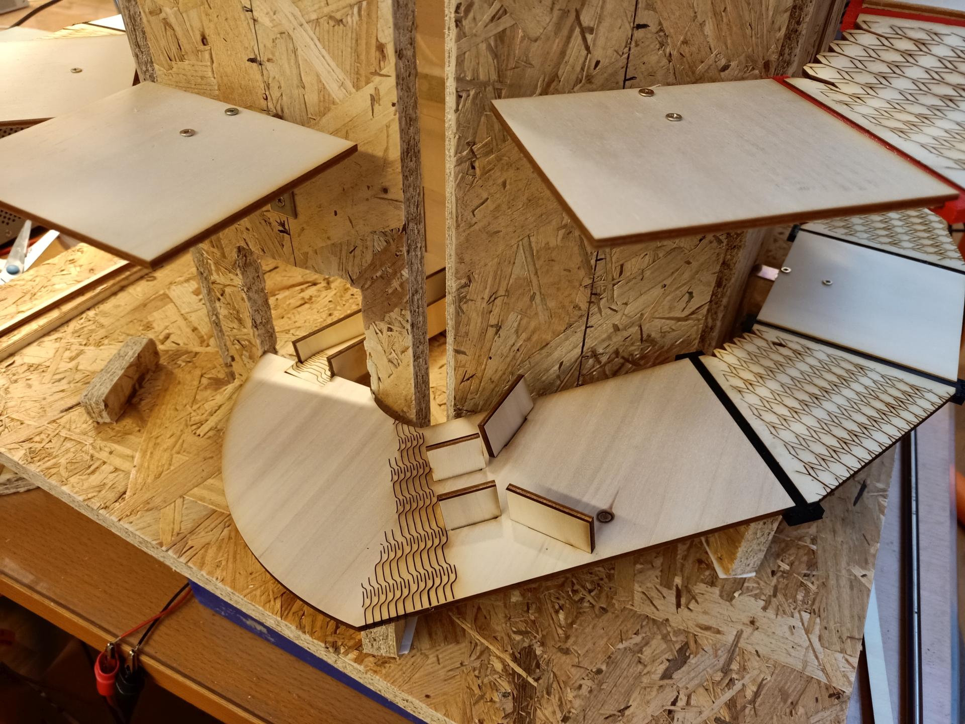
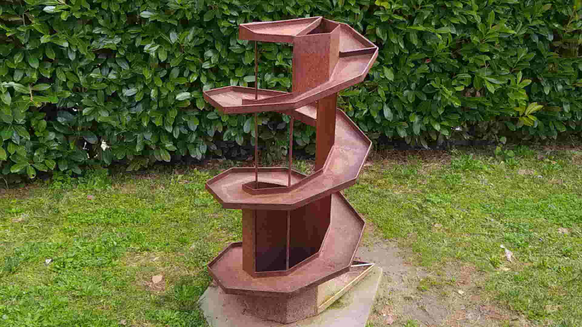
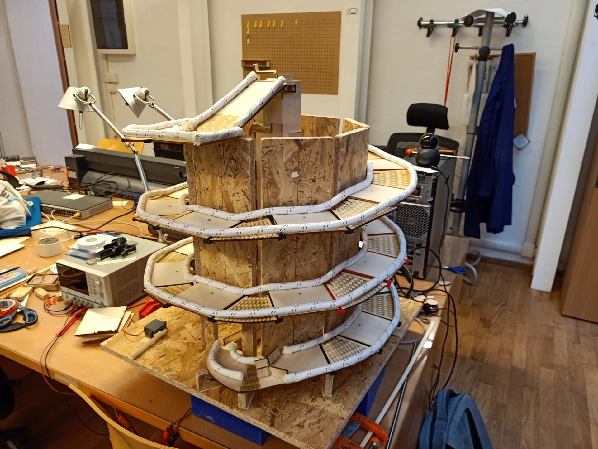
This is how the marble track looks now:
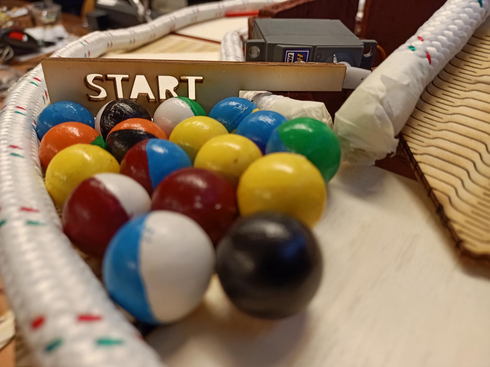
In order to prevent all the marbles to roll out of the track, I used a few meters of white thick rope on both borders. Then I put some obstacles on the track so that the marbles could find some difficulties along the race. This is how the project looks like at this point:
Then I painted the whole vertical octagonal tower, the final track section and the marble lift:
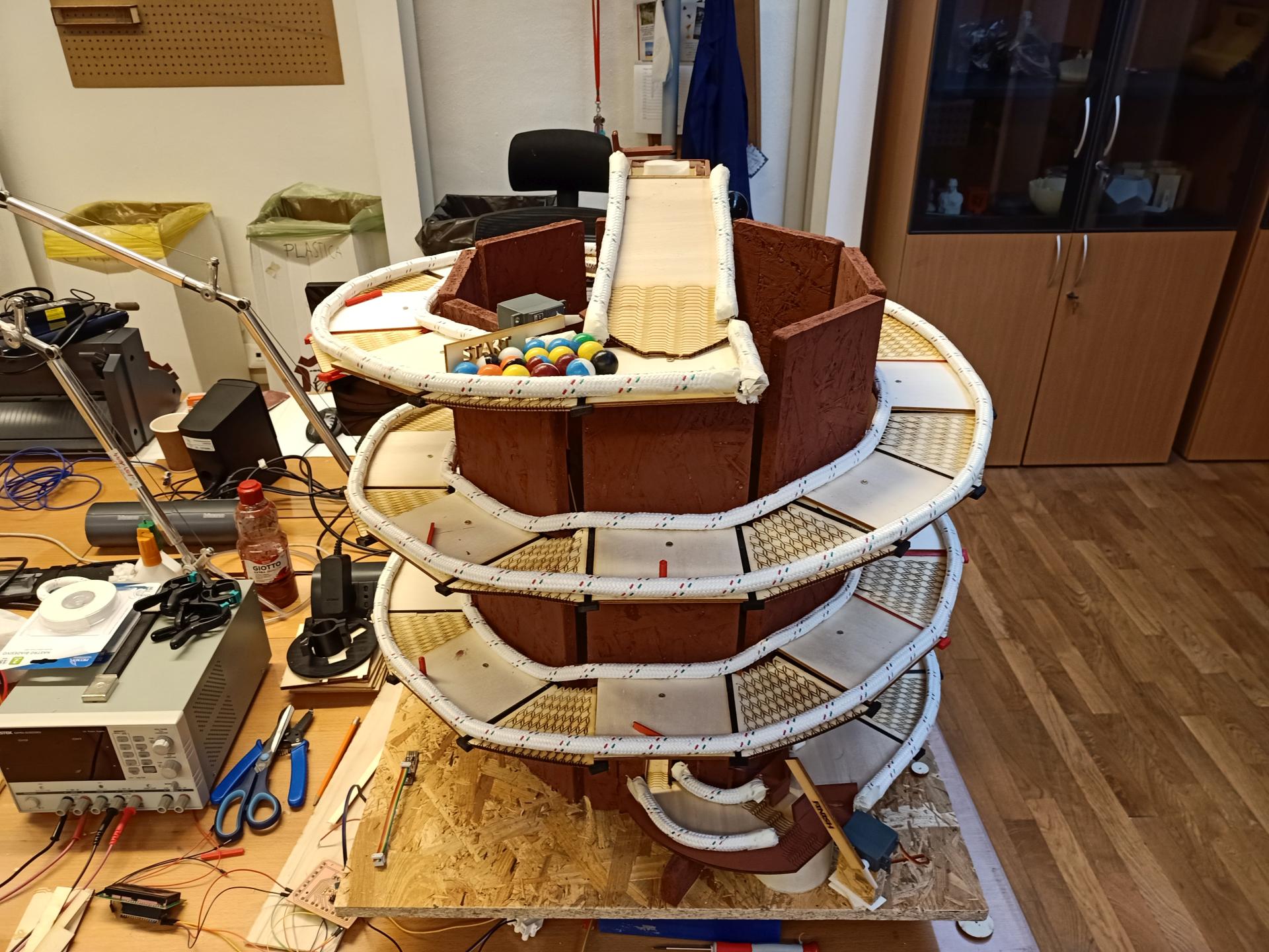
Everything’s ready for the final presentation!