9/10 . Machine and Mechanical Design
This is the assessment for this module:
Group assignment
- Design a machine that includes mechanism + actuation + automation.
- Build the mechanical parts and operate it manually.
- Actuate and automate your machine.
- Document the group project.
Individual assignment
- Document your individual contribution.
Machine concept

The machine we are building is coming straight from the Lord of the rings: Barad-dûr We want to recreate a steady tower with a rotating head. On top of the rotating head there is going to be a tilting eye. This axes should be able to recreate the effect of Sauron’s eye seeking for the ring. Inside the eye there are going to be few Neopixels in order to recreate the light beam. The head’s rotation is facilitated by a thrust bearing part, made with the Shopbot by our instructor.
The whole tower is made of laser-cut wood, both eye and mechanical parts are designed and printed. I personally designed and printed all the parts needed for the eye’s tilting system, moreover I designed and laser-cut the central structural tower where all cables are stored and where the DC motor is held so that the head can rotate with few gears. The DC motor dock has been also designed by me, starting from the file made by the students of the previous year at Santa Chiara.
Once that the whole mechanical parts are placed correctly, the programmed PCB is going to allow the user to rotate the head of the tower, to move up or down Sauron’s Eye and to turn on the Neopixels inside of it.
My contribution
I mostly contributed with the mechanical parts of the machine rather than the programming task.
I started from the design of Sauron’s Eye. I made the 3D models on Fusion360. Here’s the 3D model I made on my own:
In order to check all the workflow, this is the workfile for Fusion360: click here.
This is the 3D model of the tilting system for the eye, divided in two parts. A bigger one that is linked to the bearing on the side:
In order to check all the workflow, this is the workfile for Fusion360: click here
And another cylindrical part that connects the eye to the servomotor:
In order to check all the workflow, this is the workfile for Fusion360: click here
This is how it moves:
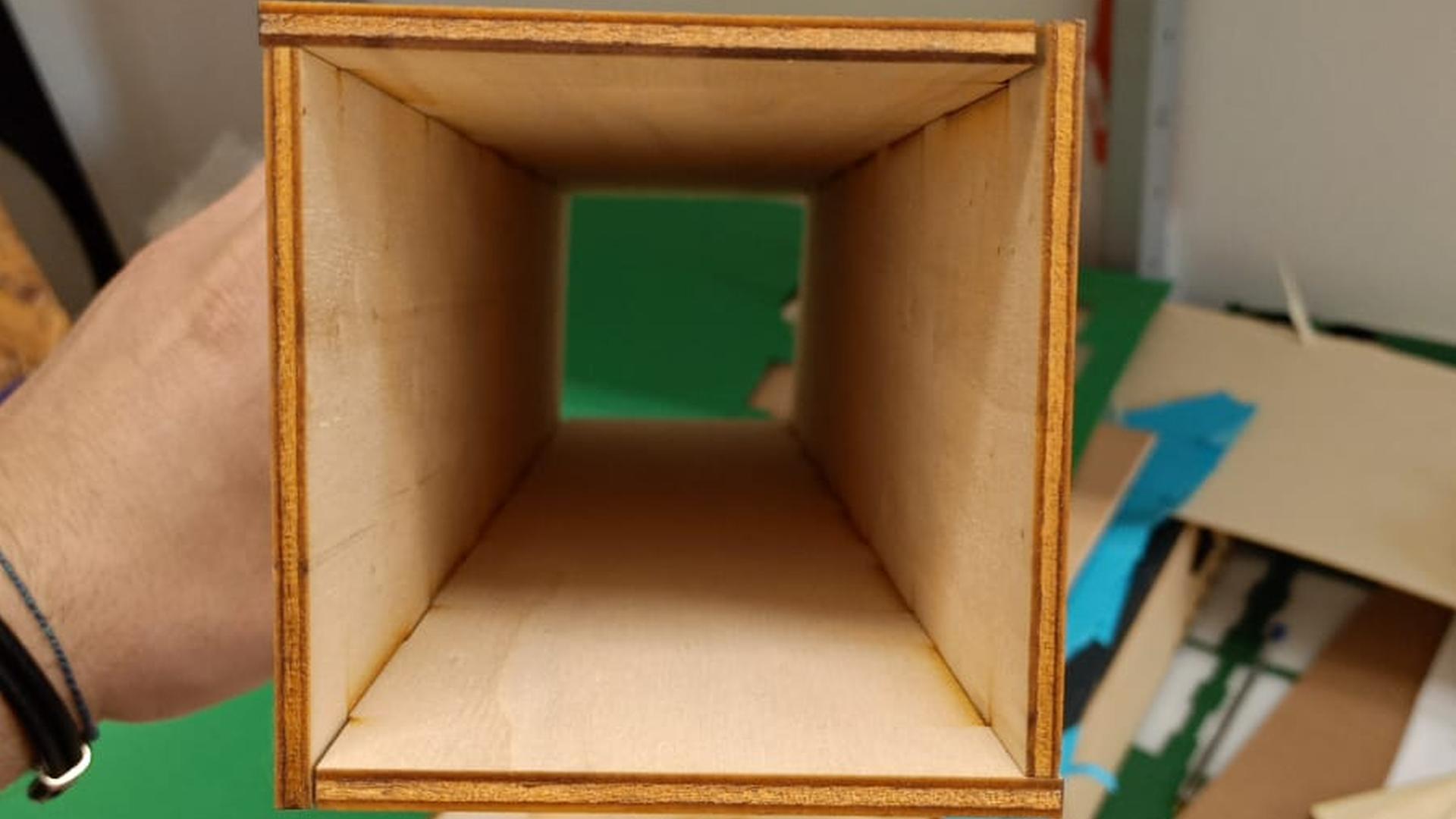
The tower must have a central structure where all the wires go from the PCB to the outputs on top. So I designed and lasercut the central wooden tower. This is the file I made for the Laser Cutter. This is how it looks out of the machine with just some tape to keep al the sides together:
Then I made the housing for the DC motor. Since the gear that rotates the head has the following structure:
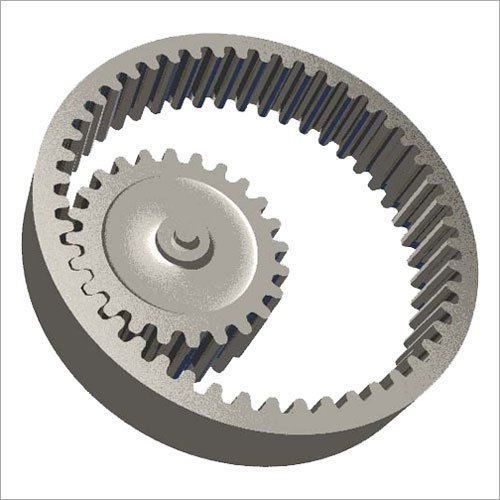
I had to make a housing that could set the gear at the very top of the thrust bearing from below, so this is the final version of the file I made:
In order to check all the workflow, this is the workfile for Fusion360: click here
Then I had to secure the wires going from the tower’s head to the bottom through the gears. So I made a piece that could protect them from the gears’ teeth while rotating.
In order to check all the workflow, this is the workfile for Fusion360: click here
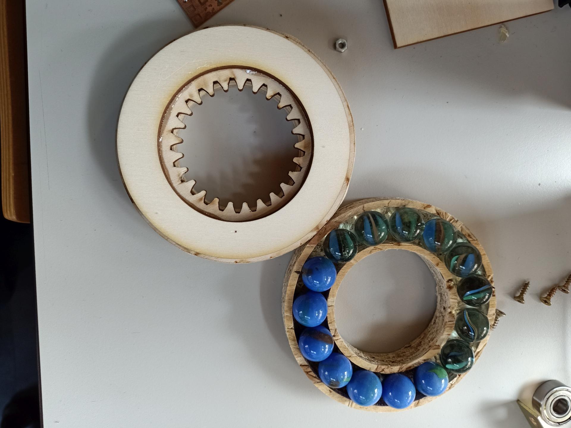
Our instructor made a thrust bearing system with two pieces of wood and some marbles. This is how it looks:
These pieces along with the thrust bearing made by our instructor work quite well during the preparation of all the components. This is the rotating surface moving thanks to the bench power supply:
The tower is going to have also a base, so that the whole structure is more stable. Along with one of my class mates we designed the whole structure on Fusion360, in order to obtain the proper DXF files for the laser cutter. Here’s the final Model I made after a few classmate’s attempts:
In order to check all the workflow, this is the workfile for Fusion360: click here
The second level is going to be held together by a crown I designed on the previous file. This is how the 3D model looks:
In order to check all the workflow, this is the workfile for Fusion360: click here
Not all the pieces on top are going to be glued. Some of the layers are held together with these supports I made:
In order to check all the workflow, this is the workfile for Fusion360: click here
Assembly
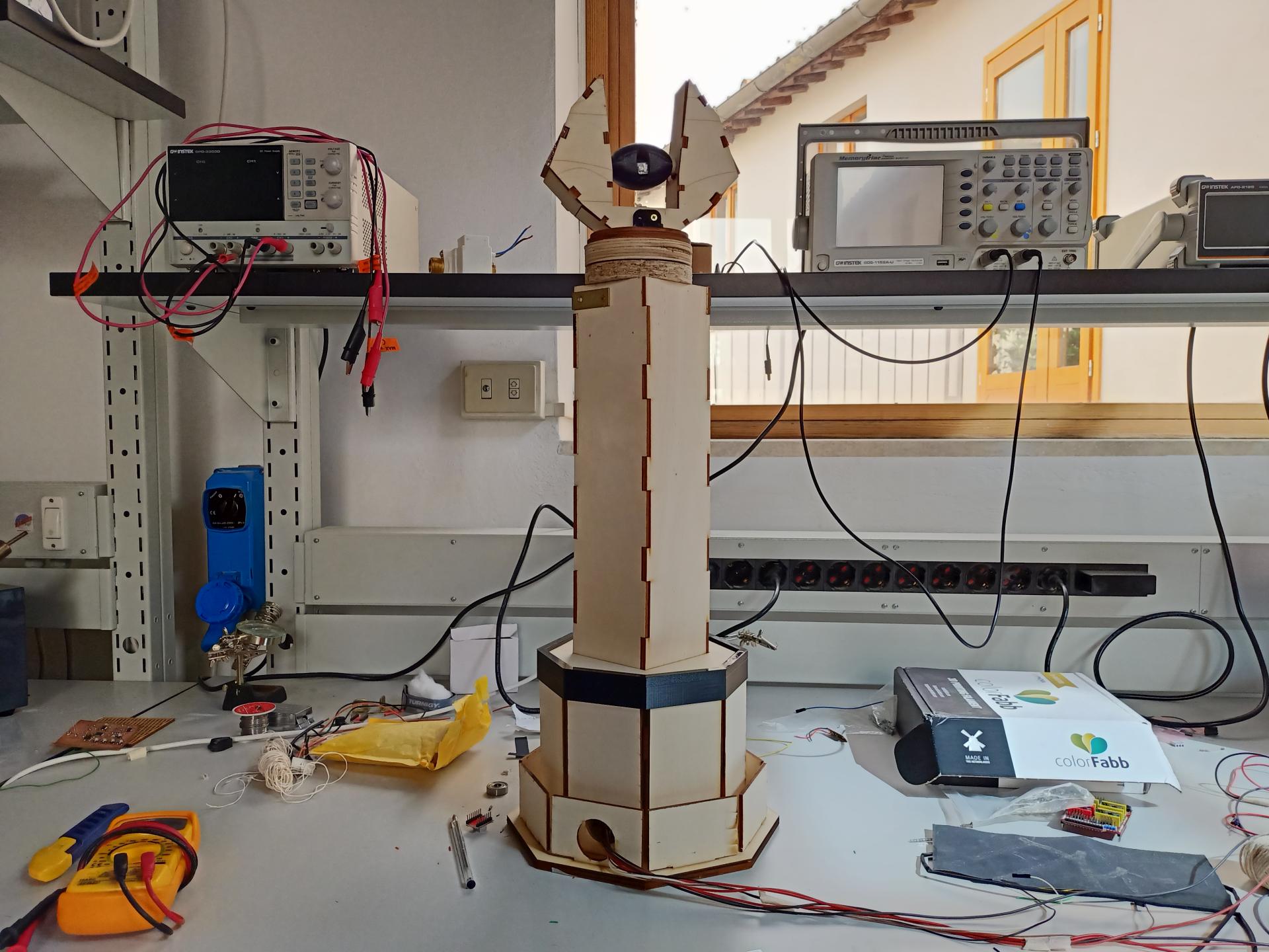
This is how the tower looks:
And this is how it moves:
Future Improvements:
The tower might be painted black, I could print and add spikes all over the tower in order to make it look more like the original one. Moreover, the buttons on the PCB might be covered by bigger buttons, just to make it easier to interact with.