13. Output Devices
This is the assessment for this module:
Group assignment
- Measure the power consumption of an output device.
Individual assignment
- Add an output device to a microcontroller board you’ve designed, and program it to do something.
Individual assignment
Servo Motor
Arduino Uno
I decided to try the Servo Motor as an output device for my next PCB. I decided to try and program a working servo motor since my final project is going to use a couple of them. They’re both going to be used for moving the gates on top and at the end of the marble track.
I started programming the board on Arduino IDE and before designing my personal brand new PCB on Eagle, I tried the device on a Arduino Uno board, in order to get along with the code, before flashing it on a freshly soldered board.
This is the code I used, taken from the sample on Tinkercad and adapted to my personal scenario:
#include <Servo.h> /*Including the servo library*/

int pos = 0; /*setting the starting position*/

Servo servo_9;

void setup()
{
  servo_9.attach(9, 500, 2500); /*setting the values for write*/

}

void loop()
{
  /*sweep the servo from 0 to 180 degrees in steps of 1 degrees*/
  for (pos = 0; pos <= 180; pos += 1) {
    /*tell servo to go to position in variable 'pos'*/
    servo_9.write(pos);
    /*wait 15 ms for servo to reach the position*/
    delay(15);
  }
  for (pos = 180; pos >= 0; pos -= 1) {
    /* tell servo to go to position in variable 'pos'*/
    servo_9.write(pos);
    /*wait 15 ms for servo to reach the position*/
    delay(15);
  }
}
And it works!
Eagle
Once the code has been tried, it was time to design a new PCB on eagle, to mill it and to solder it.
At first I tried to include two servomotors on the same PCB, so that I could use just one board to direct both gates. So I tried to use a 3x2 connector but I kept the 5V voltage, which might be rather low to make both move contemporarily.
This is the schematic of my first output PCB:
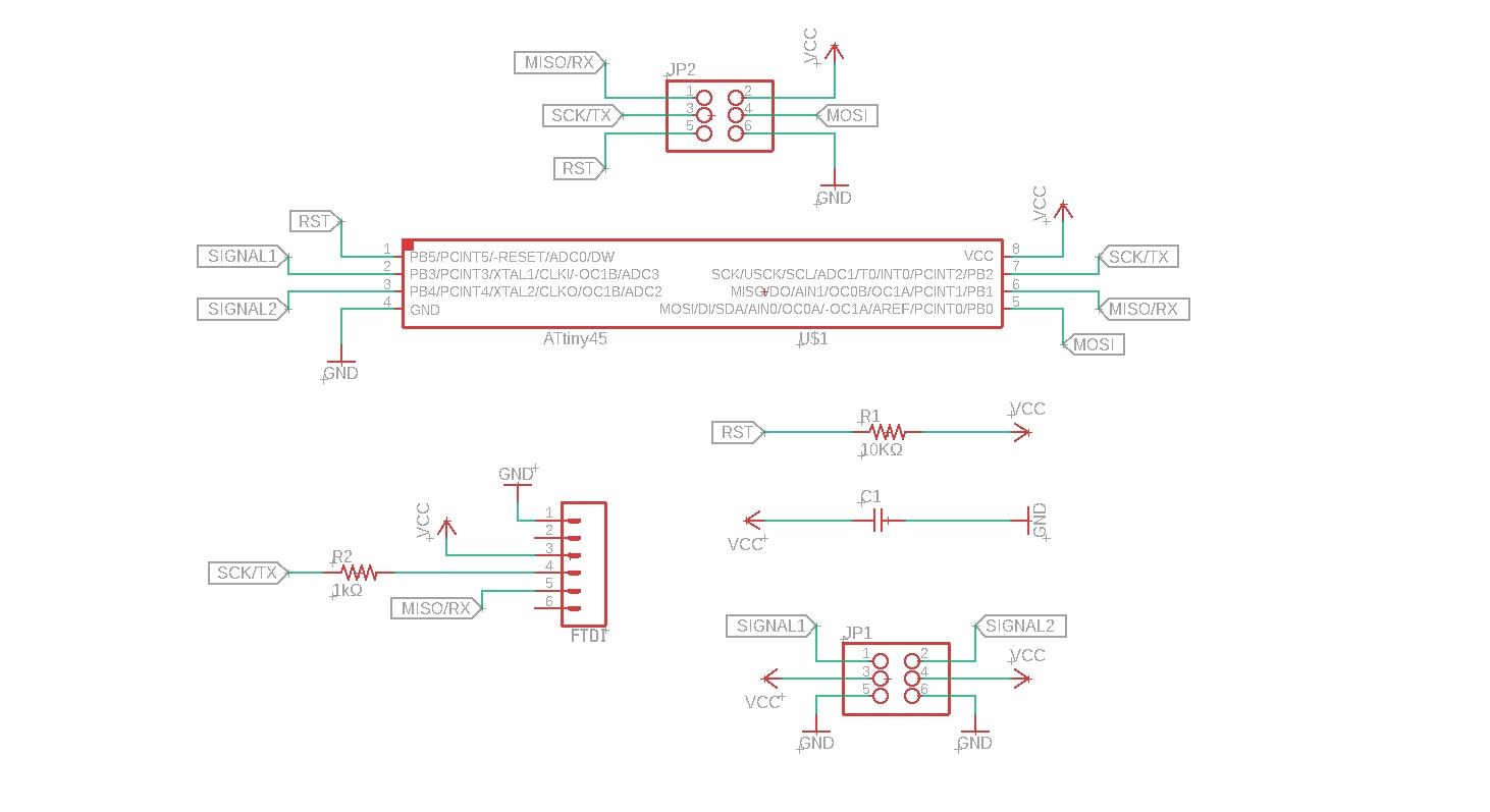
You can download it here
And this is its board:
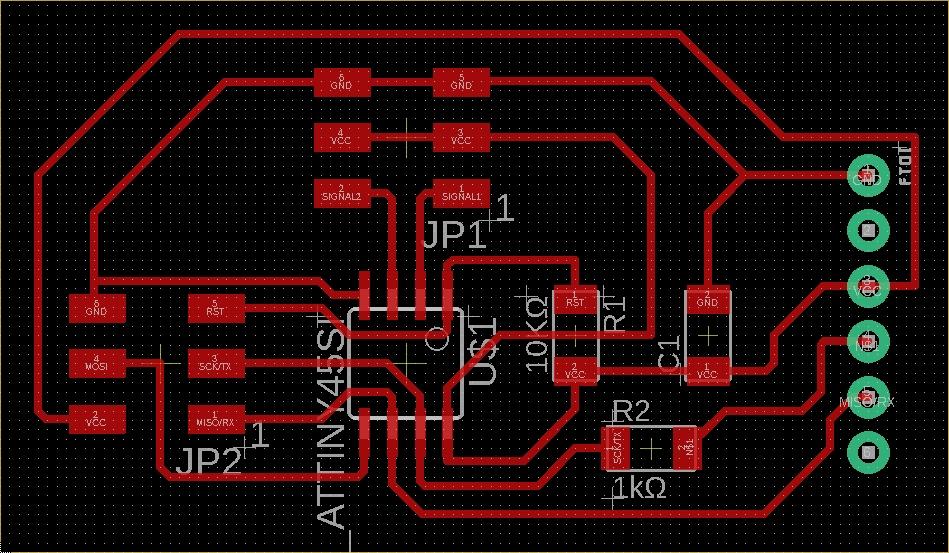
You can download it here
Then, since I knew that I could move one servo more easily and quickly, I designed a second board starting from the previous one. This board, with a 3x1 connector, can use only one servomotor, but the 5V voltage is enough for its job.
This is the schematic of my second output PCB:
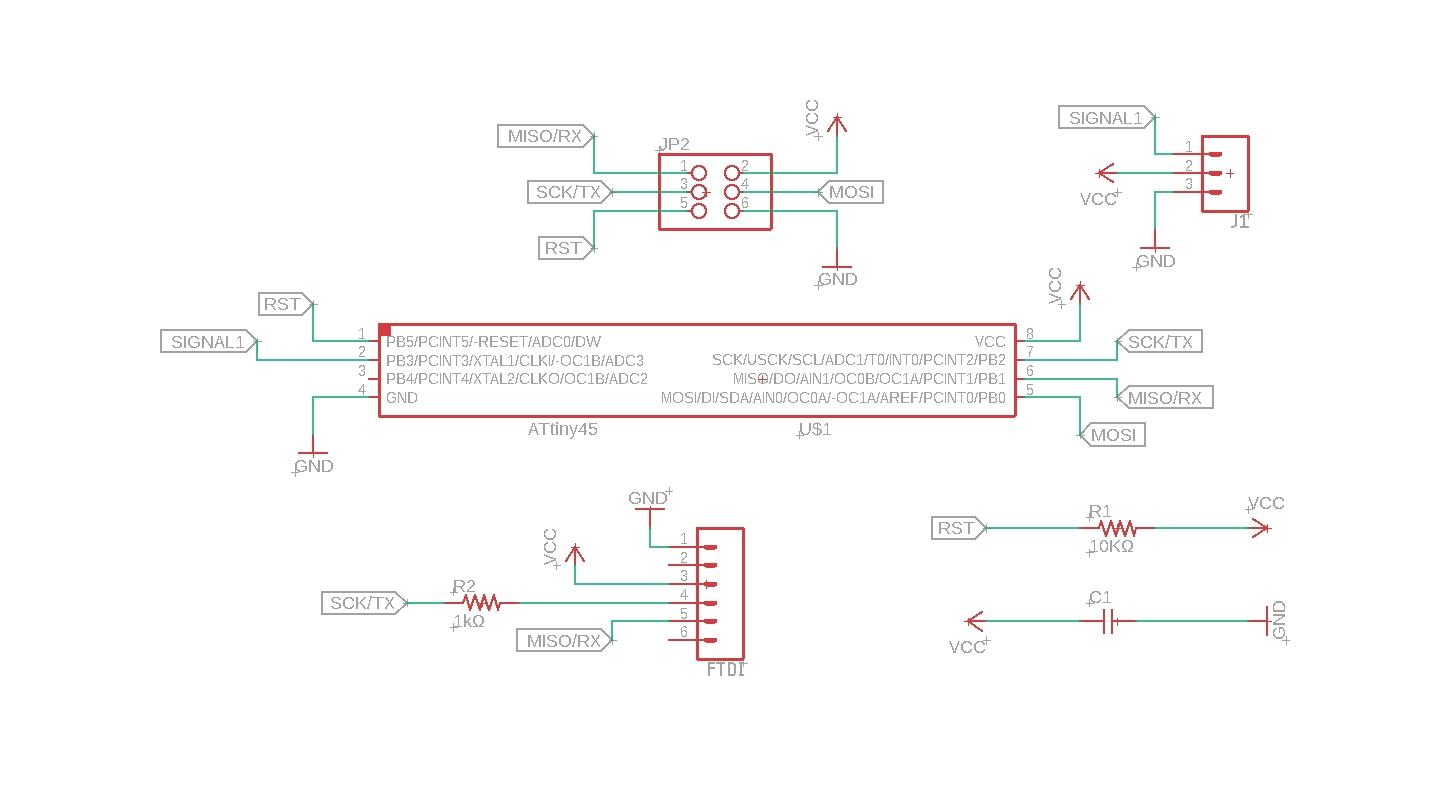
You can download it here
And this is its board:
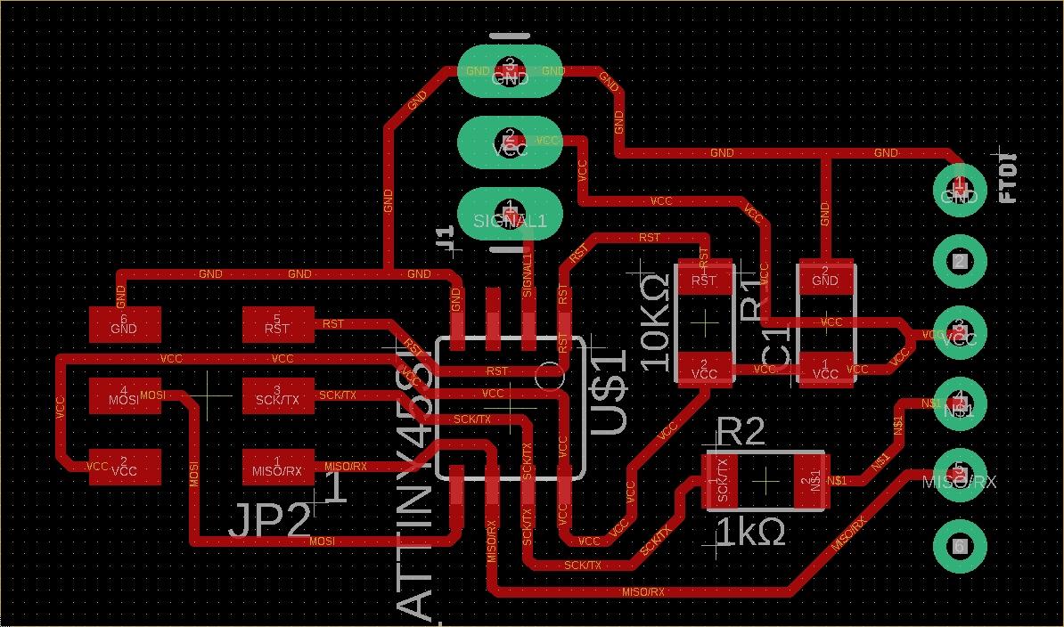
You can download it here
Editing the PNG files
Then I moved on with Photoshop, Mods and next I milled the copper board.
Here it is possible to download the png files I used on Mods:
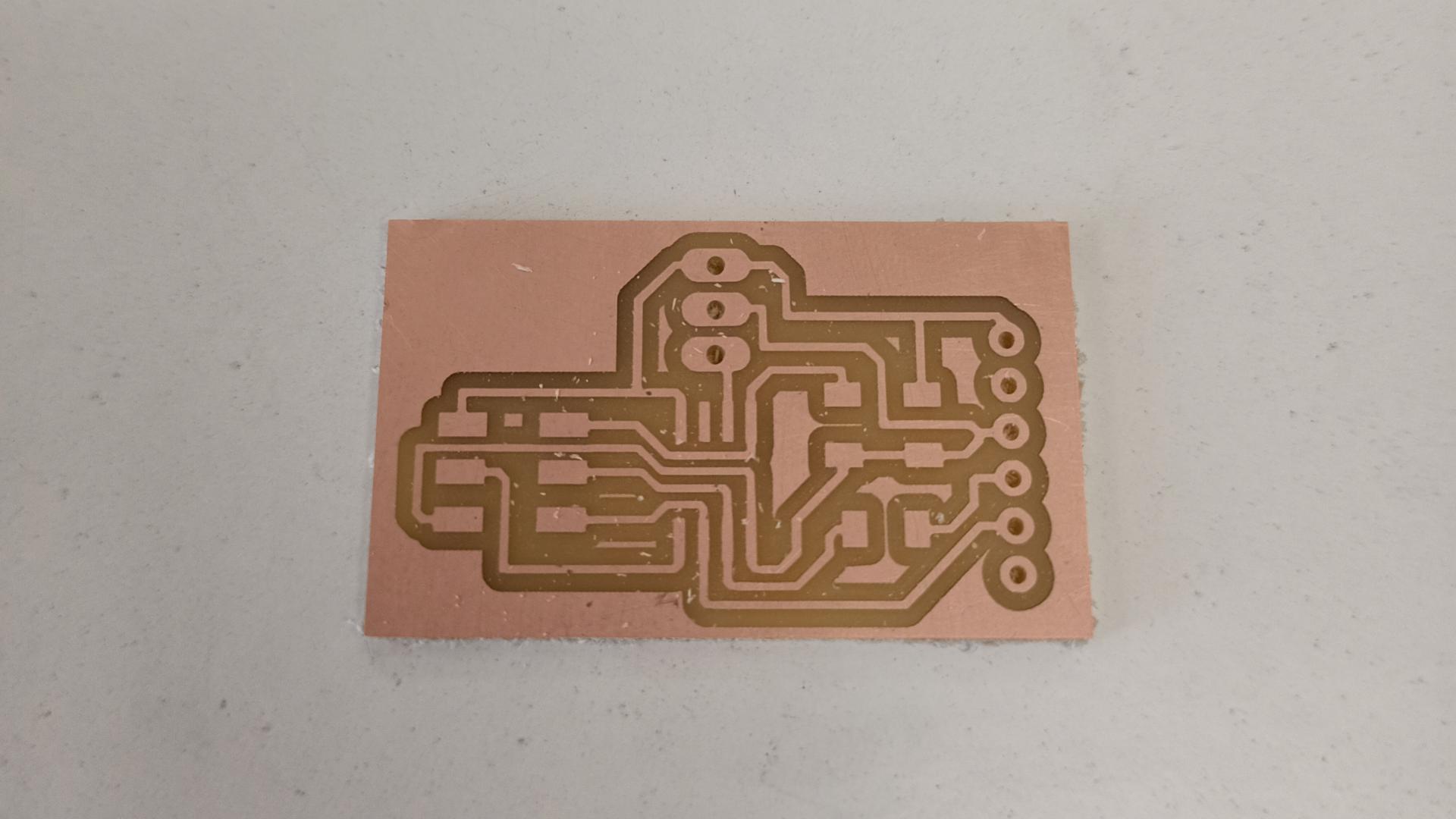
Milling and Soldering
This is the board out of the Roland SRM-20:
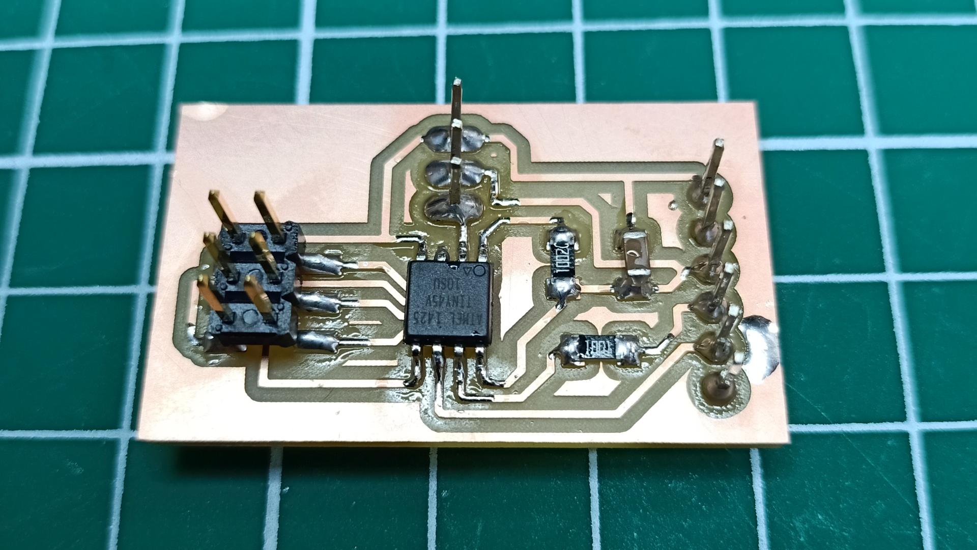
This is the board at the end of the soldering process:
Programming the PCB
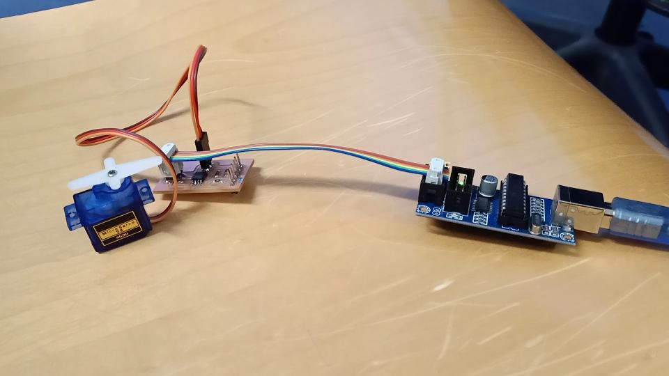
This week the programming part on the PCB has been quite tricky. I had to try three different approaches before making the servo motor move properly.
At first I tried with the Arduino IDE along with the code used previously. Unfortunately the
I decided to try with a lower level approach, using the C code provided by Neil (this one). I applied the necessary changes to it and then I tried to make it run.
The servomotor did not move at all. Unfortunately the original code is for an ATtiny44, which uses two of its pins to communicate as a 16-bit controller even if it is a 8-bit just like the ATtiny45.
So I decided to look online for a Servomotor library that can connect a servomotor to a 8-bit microcontroller.
I found this one which seemed quite trustworthy.
I took the example code and pasted it on the Arduino IDE. At first I did not realize that the code was not considering the Arduino syntax at all, so I tried to upload it and nothing happened. The problem is that this library uses delay not as intended by the IDE. The Arduno IDE uses delay which is based milliseconds, this code uses microseconds. I had to use the toolchain in order to make this code work.
This is the makefile I used:
PORT = usb

TARGET = example

ARDUINO =

SRC =

CXXSRC = $(TARGET).cpp Servo8Bit.cpp

MCU = attiny45


F_CPU = 8000000

FORMAT = ihex


# Name of this Makefile (used for "make depend").
MAKEFILE = Makefile

# Debugging format.
# Native formats for AVR-GCC's -g are stabs [default], or dwarf-2.
# AVR (extended) COFF requires stabs, plus an avr-objcopy run.
DEBUG = stabs

OPT = s

# Place -D or -U options here
CDEFS = -DF_CPU=$(F_CPU)
CXXDEFS = -DF_CPU=$(F_CPU)

# Place -I options here
CINCS = -I$(ARDUINO)
CXXINCS = -I$(ARDUINO)

# Compiler flag to set the C Standard level.
# c89   - "ANSI" C
# gnu89 - c89 plus GCC extensions
# c99   - ISO C99 standard (not yet fully implemented)
# gnu99 - c99 plus GCC extensions
CSTANDARD = -std=gnu99
CDEBUG = -g$(DEBUG)
CWARN = -Wall -Wstrict-prototypes
CTUNING = -funsigned-char -funsigned-bitfields -fpack-struct -fshort-enums
#CEXTRA = -Wa,-adhlns=$(<:.c=.lst)

CFLAGS = $(CDEBUG) $(CDEFS) $(CINCS) -O$(OPT) $(CWARN) $(CSTANDARD) $(CEXTRA)
CXXFLAGS = $(CDEFS) $(CINCS) -O$(OPT)
#ASFLAGS = -Wa,-adhlns=$(<:.S=.lst),-gstabs
LDFLAGS =


# Programming support using avrdude. Settings and variables.
AVRDUDE_PROGRAMMER = usbtiny
AVRDUDE_PORT = $(PORT)
AVRDUDE_WRITE_FLASH = -U flash:w:$(TARGET).hex
AVRDUDE_FLAGS = -F -p $(MCU) -P $(AVRDUDE_PORT) -c $(AVRDUDE_PROGRAMMER)

# Program settings
CC = avr-gcc
CXX = avr-g++
OBJCOPY = avr-objcopy
OBJDUMP = avr-objdump
SIZE = avr-size
NM = avr-nm
AVRDUDE = avrdude
REMOVE = rm -f
MV = mv -f

# Define all object files.
OBJ = $(SRC:.c=.o) $(CXXSRC:.cpp=.o) $(ASRC:.S=.o)

# Define all listing files.
LST = $(ASRC:.S=.lst) $(CXXSRC:.cpp=.lst) $(SRC:.c=.lst)

# Combine all necessary flags and optional flags.
# Add target processor to flags.
ALL_CFLAGS = -mmcu=$(MCU) -I. $(CFLAGS)
ALL_CXXFLAGS = -mmcu=$(MCU) -I. $(CXXFLAGS)
ALL_ASFLAGS = -mmcu=$(MCU) -I. -x assembler-with-cpp $(ASFLAGS)


# Default target.
all: build

build: elf hex

elf: $(TARGET).elf
hex: $(TARGET).hex
eep: $(TARGET).eep
lss: $(TARGET).lss
sym: $(TARGET).sym

# Program the device.
upload: $(TARGET).hex
    $(AVRDUDE) $(AVRDUDE_FLAGS) $(AVRDUDE_WRITE_FLASH)


# Convert ELF to COFF for use in debugging / simulating in AVR Studio or VMLAB.
COFFCONVERT=$(OBJCOPY) --debugging \
--change-section-address .data-0x800000 \
--change-section-address .bss-0x800000 \
--change-section-address .noinit-0x800000 \
--change-section-address .eeprom-0x810000


coff: $(TARGET).elf
    $(COFFCONVERT) -O coff-avr $(TARGET).elf $(TARGET).cof


extcoff: $(TARGET).elf
    $(COFFCONVERT) -O coff-ext-avr $(TARGET).elf $(TARGET).cof


.SUFFIXES: .elf .hex .eep .lss .sym

.elf.hex:
    $(OBJCOPY) -O $(FORMAT) -R .eeprom $< $@

.elf.eep:
    -$(OBJCOPY) -j .eeprom --set-section-flags=.eeprom="alloc,load" \
    --change-section-lma .eeprom=0 -O $(FORMAT) $< $@

# Create extended listing file from ELF output file.
.elf.lss:
    $(OBJDUMP) -h -S $< > $@

# Create a symbol table from ELF output file.
.elf.sym:
    $(NM) -n $< > $@


# Link: create ELF output file from object files.
$(TARGET).elf: $(OBJ)
    $(CC) $(ALL_CFLAGS) $(OBJ) --output $@ $(LDFLAGS)


# Compile: create object files from C++ source files.
.cpp.o:
    $(CXX) -c $(ALL_CXXFLAGS) $< -o $@

# Compile: create object files from C source files.
.c.o:
    $(CC) -c $(ALL_CFLAGS) $< -o $@


# Compile: create assembler files from C source files.
.c.s:
    $(CC) -S $(ALL_CFLAGS) $< -o $@


# Assemble: create object files from assembler source files.
.S.o:
    $(CC) -c $(ALL_ASFLAGS) $< -o $@


# Target: clean project.
clean:
    $(REMOVE) $(TARGET).hex $(TARGET).eep $(TARGET).cof $(TARGET).elf \
    $(TARGET).map $(TARGET).sym $(TARGET).lss \
    $(OBJ) $(LST) $(SRC:.c=.s) $(SRC:.c=.d) $(CXXSRC:.cpp=.s) $(CXXSRC:.cpp=.d)

depend:
    if grep '^# DO NOT DELETE' $(MAKEFILE) >/dev/null; \
    then \
        sed -e '/^# DO NOT DELETE/,$$d' $(MAKEFILE) > \
            $(MAKEFILE).$$$$ && \
        $(MV) $(MAKEFILE).$$$$ $(MAKEFILE); \
    fi
    echo '# DO NOT DELETE THIS LINE -- make depend depends on it.' \
        >> $(MAKEFILE); \
    $(CC) -M -mmcu=$(MCU) $(CDEFS) $(CINCS) $(SRC) $(ASRC) >> $(MAKEFILE)

.PHONY: all build elf hex eep lss sym program coff extcoff clean depend
And this is the code I compiled with avrdude:
#include "Servo8Bit.h"

void delay(uint16_t milliseconds);  //forward declaration to the delay function


int main()
{
    Servo8Bit myServo;  //create a servo object.
                        //a maximum of five servo objects can be created

    myServo.attach(3);  //attach the servo to pin PB3


    myServo.write(0);   //rotate to the 0 degree position
    delay(2000);        //wait 2 seconds

    myServo.write(180); //rotate to the 180 degree position
    delay(2000);        //wait 2 seconds

    myServo.write(90);  //rotate to the center (90 degree) position
    delay(2000);        //wait 2 seconds


    //sweep the servo
    while(1)
    {
        for(int pos = 0; pos < 180; pos++)  // goes from 0 degrees to 180 degrees
        {                                   // in steps of 1 degree
            myServo.write(pos);             // tell servo to go to position in variable 'pos'
            delay(15);                      // waits 15ms for the servo to reach the position
        }

        for(int pos = 180; pos > 1; pos--)  // goes from 180 degrees to 0 degrees
        {
            myServo.write(pos);             // tell servo to go to position in variable 'pos'
            delay(15);                      // waits 15ms for the servo to reach the position
        }
    }
}


void delayMicroseconds(uint16_t us)
{
#if F_CPU >= 16000000L
    // for the 16 MHz clock on most Arduino boards

    // for a one-microsecond delay, simply return.  the overhead
    // of the function call yields a delay of approximately 1 1/8 us.
    if (--us == 0)
        return;

    // the following loop takes a quarter of a microsecond (4 cycles)
    // per iteration, so execute it four times for each microsecond of
    // delay requested.
    us <<= 2;

    // account for the time taken in the preceeding commands.
    us -= 2;
#else
    // for the 8 MHz internal clock on the ATmega168

    // for a one- or two-microsecond delay, simply return.  the overhead of
    // the function calls takes more than two microseconds.  can't just
    // subtract two, since us is unsigned; we'd overflow.
    if (--us == 0)
        return;
    if (--us == 0)
        return;

    // the following loop takes half of a microsecond (4 cycles)
    // per iteration, so execute it twice for each microsecond of
    // delay requested.
    us <<= 1;

    // partially compensate for the time taken by the preceeding commands.
    // we can't subtract any more than this or we'd overflow w/ small delays.
    us--;
#endif

    // busy wait
    __asm__ __volatile__ (
        "1: sbiw %0,1" "\n\t" // 2 cycles
        "brne 1b" : "=w" (us) : "0" (us) // 2 cycles
    );
}//end delayMicroseconds


void delay(uint16_t milliseconds)
{
    for(uint16_t i = 0; i < milliseconds; i++)
    {
        delayMicroseconds(1000);
    }
}//end delay
Finally the servomotor moves!
DC Motor
Arduino Uno
Since I am going to need a marble lifting system for my final project, I decided give my DC motor a go with an Arduino Uno Board.
Using the Arduino IDE, I found the instructions about the code on the following sites:
Here’s the code I used:
#include <Servo.h> /*Including the servo library*/

int pos = 0; /*setting the starting position*/

Servo servo_9;

void setup()
{
  servo_9.attach(9, 500, 2500); /*setting the values for write*/

}

void loop()
{
  /*sweep the servo from 0 to 180 degrees in steps of 1 degrees*/
  for (pos = 0; pos <= 180; pos += 1) {
    /*tell servo to go to position in variable 'pos'*/
    servo_9.write(pos);
    /*wait 15 ms for servo to reach the position*/
    delay(15);
  }
  for (pos = 180; pos >= 0; pos -= 1) {
    /* tell servo to go to position in variable 'pos'*/
    servo_9.write(pos);
    /*wait 15 ms for servo to reach the position*/
    delay(15);
  }
}
As you can see, the motor works properly. I attached a little fan to it, so that the movement can be seen more easily.
Group assignment
We decided to test the energy consumption of a DC motor, more specifically the DC motor with reduction we used in our group project during week 9 and 10.
We turned the DC motor on through our bench power supply and instantly the ampere absorption was 0.09A. If the motor runs without any load or resistance, this is the regular absorption. Trying to hold the DC motor, its power absorption increases proportionally to the load/weight it has to carry or move. The following video shows how the absorption rises and gets lower as the DC motor’s work gets heavier or lighter. The power absorption goes from 0.09A to 0.25A as the load gets heavier.