7. Embedded Programming
This is the assessment for this module:
Group assignment
- Compare the performance and development workflows for other architectures.
Individual assignment
- Read a microcontroller data sheet.
- Program your board to do something with as many different programming languages and programming environments as possible.
Individual assignment
This week I had to learn the basics of embedded programming. I found the documentation of few former Santa Chiara students really useful. Simone Guercio and even moreElena Racanicchi.
Another important tool for understanding the basics of this world has been Make: AVR programming by Elliot Williams. The first chapters have helped me understanding more clearly many concepts. This doesn’t mean that everything ran smoothly. Rather the opposite…
THEORY
Let’s start with some theory about microcontrollers:
ARCHITECTURE
We are using microcontrollers made with HARVARD Architecture. The program and the data are stored in different memories.
MEMORY
The memories our microcontrollers have inside are used for different purposes. Comparing them to computers, the FLASH memory works as the hard disk, it stores the code even when there is no power supply. The programs are processed through the RAM. The more it is, the more complex the code can be loaded. If the flash memory is used to store the firmware, the EEPROM memory can store history and settings for the microcontroller even when the power runs out, without any loss. Then there are the FUSES, which are a specific bit of memory stored in the microcontroller that contain specific settings. Usually when we start designing a PCB, we pick specific parts, like oscillators, timers, counters and even more that must be regulated through the fuses. There are three types of fuses. They are bytes that regulate our microcontroller:
- Fuse Extended byte
- Fuse High byte
- Fuse Low byte
In datasheets fuse bytes are commonly explained in the memory programming paragraph.
PERIPHERALS
Microcontrollers differ in size, this difference occurs in the number of available pins as well (e.g. ATtiny45 has 8 pins and ATtiny44 has 14 pins). Each PIN belongs to a microcontroller’s PORT. Analog sources, like voltage, can be transformed into digital feedback through the A/D CONVERTER. Of course there are faster tools for measuring and comparing these sources, like the COMPARATOR, which can compare two voltages and tell which is the bigger. In some microcontrollers there can be a D/A CONVERTER too, that can give an analogical feedback, like the waves. Then there are peripherals like TIMERS and COUNTERS, that do what their name suggest: they measure time or count the amount of times something occurs. Some outputs react properly if the voltage is turned on and off quickly rather than varied gradually: It is all a heat matter, and this is what PMW (pulse width modulation) does. Data can transferred via ports, but the type of port we use changes the way we move data. USB PORTS send multiple data simultaneously (it is a parallel port), while the USART PORTS send binary data alternately (it is a serial port).
WORD SIZE
Bigger processor have bigger memories that can do more works in one operation. Generally, a bigger word size is better, but even a simple 8 bit processor can run most of the operations we need. More space means more simultaneous variety, but the things a bigger processor does can Identically be done by a small one.
IN-SYSTEM PROGRAMMING
Processors need to be programmed in order to do what they are made for. This is what in-system programming is all about, loading programs inside boards’ memories.
There are are many ways to do that:
- Pin-header connectors on the board are used to load the program from the programmer.
- The pads can be connected temporarily on the board without soldering them, just holding them onto the board while loading the program.
- It is possible to send the signal directly to the processor with the clips, without any connector on the board.
- Pogo pins are a further alternative.
PROGRAMMING LANGUAGES
It is necessary to use a programming language when we want to give order to a machine. Programming languages can be divided into two main categories:
HIGH-END LANGUAGES (Python, Arduino, Java) the syntaxes are similar to the spoken language so, instead of compiling low level code you write high level command and the machine translates it, obviously this process takes more time than the other one.
LOW-END LANGUAGES (Assembly, C, C++, C#) have syntaxes closer to pure machine language, which is more difficult to be understood. Since it is more cryptic and requires a highly specified competences, its performance is way faster than the previous category.
WHAT WE NEED FOR EMBEDDED PROGRAMMING?
- A toolchain to programm the AVR board. In my case I used a PC with Linux on it.
- A firmware which is the C code I write on my text-editor (Sublime).
- A compiler,(I used AVR-GCC, which is included in the previous toolchain) that tranforms the C code file into machine language (.hex).
- A hardware programmer that can load the firmware into your board.
- A software programmer like avrdude that digitally starts the programming process.
PROGRAMMING IN C
Programming in C means using a low-end level, so its syntax might be quite complicated if compared to other mainstream languages. This steeper learning curve is counterbalanced by a quicker programming speed and a lighter source code.
DATA SHEET
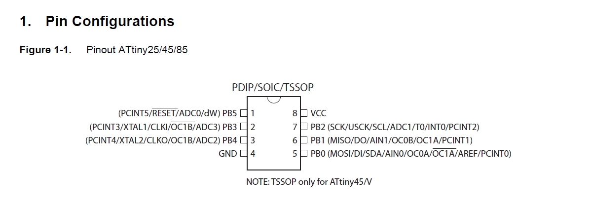
In order to create a completely working source code, it is necessary to read and check the microcontroller’s datasheet. Its size might scare at first, but some paragraph are fundamental for programmers and not so difficult to read even for makers with any engineering background. In my case, since I used an ATtiny45, this is the datasheet I had to read.
This is the microcontroller’s structure as shown on the datasheet, with all the PIN configurations:
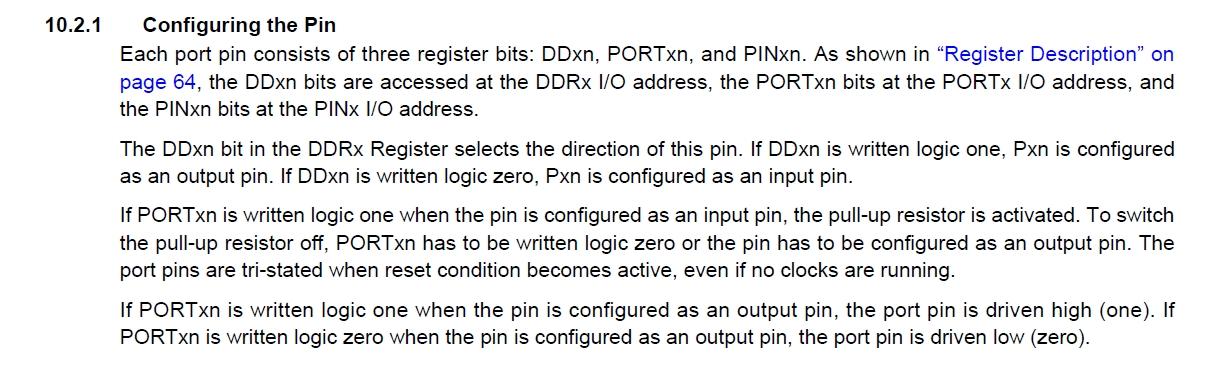
Most of the things I needed for programming the ATtiny45 could be found in chapter 10: I/O Ports. The first thing I looked for is how to set the internal pull-up resistor for the switch, since I did not solder any externally. As you can see below, the internal pull-up resistor can be turned on this way:
1. set the switch button as an input pin with DDRB (ATtiny45 does not have A pins).
2. write a logic one on its port with PORTB, turning on the resistor for that pin.
Other microcontrollers might need external sources like crystal oscillators, which need more than the regular MHz provided by the microcontroller. My setup with the ATtiny45 didn’t need any change on the Fuse Low byte, but If I had to, like usually the ATtiny44 does, the chapter 20: Memory Programming on the datasheet might have done the job with all the possible fuse settings. If you need help in calculating what has to be done and communicated to the microcontroller, you can use a fuse calculator like this one or this one.
MAKEFILE
The whole toolchain is driven by the Makefile (be sure to name it with capital M). All the commands given while compiling or flashing the programm on the programmee board are going to follow the instructions written inside this file. Let’s dive into it, towards explaining the basics. This is the makefile provided by Neil right on the schedule:
PROJECT=hello.ftdi.45.port
SOURCES=$(PROJECT).c
MMCU=attiny45
F_CPU = 8000000

CFLAGS=-mmcu=$(MMCU) -Wall -Os -DF_CPU=$(F_CPU)

$(PROJECT).hex: $(PROJECT).out
    avr-objcopy -O ihex $(PROJECT).out $(PROJECT).c.hex;\
    avr-size --mcu=$(MMCU) --format=avr $(PROJECT).out

$(PROJECT).out: $(SOURCES)
    avr-gcc $(CFLAGS) -I./ -o $(PROJECT).out $(SOURCES)

program-bsd: $(PROJECT).hex
    avrdude -p t45 -c bsd -U flash:w:$(PROJECT).c.hex

program-dasa: $(PROJECT).hex
    avrdude -p t45 -P /dev/ttyUSB0 -c dasa -U flash:w:$(PROJECT).c.hex

program-avrisp2: $(PROJECT).hex
    avrdude -p t45 -P usb -c avrisp2 -U flash:w:$(PROJECT).c.hex

program-usbtiny: $(PROJECT).hex
    avrdude -p t45 -P usb -c usbtiny -U flash:w:$(PROJECT).c.hex

program-dragon: $(PROJECT).hex
    avrdude -p t45 -P usb -c dragon_isp -U flash:w:$(PROJECT).c.hex

program-ice: $(PROJECT).hex
    avrdude -p t45 -P usb -c atmelice_isp -U flash:w:$(PROJECT).c.hex
Our makefile is going to be slimmer, since Neil included more options. I used and usbtiny as the programmer board, so I removed all the commands that mentioned different programmer types (Atmel Ice, Dragon, AVR ISP). The top rows are the one we are gonna change more frequently, since PROJECT and SOURCES specify the name of the project we are working on. Then MMCU must be filled with the type of AVR chip we’re using, while F_CPU asks for what clock speed our chip is running at. This is usually either 8000000 for ATtiny44/45.
The flags we set into the makefile are shortcuts that are easy for us to write but they still communicate a bunch of different commands to the compiler.
This list of AVRDUDE options that follows can be quite helpful and self-explanatory on what those commands written previously might mean:
-
-c
Here you specify the type of flash programmer that you’re using. I kept -c usbtiny. If you’d like to see the full list, typeavrdude -c ?. -
-p
Here you specify the type of AVR chip that you’re programming for. In my case “t45” stands for ATtiny45 chip. -
-P
If you’re not using a native USB programmer (for instance, if you’re using an ArduinoISP), you’ll need to know which serial port the programmer is connected to. My usbtiny just needed to be set with -P usb. -
-U
This the command that reads or writes to memory. You’ll almost always be calling this from a makefile. You must specify the memory you’re writing into, usually it is flash.W stands for write, then you must specify the name of the c and hex files to look for into the folder.
This is the makefile I used and kept for this week:
PROJECT=name of the project
SOURCES=$[PROJECT].c
MMCU=attiny45
F_CPU = 8000000

CFLAGS= -mmcu=$(MMCU) -Wall -Os -DF_CPU=$(F_CPU)

$(PROJECT).hex: $(PROJECT).out
        avr-objcopy -O ihex $(PROJECT).out $(PROJECT).c.hex;\
        avr-size --mcu=$(MMCU) --format=avr $(PROJECT).out

$(PROJECT).out: $(SOURCES)
        avr-gcc $(CFLAGS) -I./ -o $(PROJECT).out $(SOURCES)

program-usbtiny: $(PROJECT).hex
        avrdude -p t45 -P usb -c usbtiny -U flash:w:$(PROJECT).c.hex
WRITING THE CODE
Once the makefile was ready and I took a look into the datasheet, I started writing the source code in C.
I focused on setting the registers:
-
DDR: Data Direction Register > it determines the condition of the PIN if it is a Input or Output PIN.
-
PORT: Gives power to those pins that DDR defined output pins.
-
PIN: gives the feedback about every pin, saying if it is a output or input. This register cannot be changed, it is used to show and double check if DDR and port have been set up properly.
I wrote a simple code for a simple task. The following code made blink the green LED on the hello board.
#include <avr/io.h>         /*including the libraries I need*/
#include <util/delay.h>

int main() {
    DDRB = 0b00001000;      /*defining PB03 pin as output*/

    while(1) {              /*loop*/
        PORTB = 0b00001000; /*turning on PB03*/
        _delay_ms(500);     /*waiting half second*/

        PORTB = 0b00000000; /*turning off PB03*/
        _delay_ms(500);     /*waiting half*/
    }

    return (0);             /*closing the main function*/

}
And it blinked!
Then I moved on to something trickier. I wanted to turn on the LED only while the switch was pushed. I had a hard time trying to sort out the proper code, I had some issues on I/O ports setting with DDRB. In the end this is the code that did the job:
#include <avr/io.h>                             /*including the libraries I need*/
#include <util/delay.h>

int main() {
    DDRB = 0;                                   /*setting all the pins as input*/
    PORTB |= (1<<4);                            /*turning on the internal pull-up resistor*/
    DDRB |= (1<<3);                             /*defining PB03 pin as the only output*/
    _delay_ms(500);                             /*making a little delay before the while cycle*/

    while(1) {                                  /*loop*/

        if((PINB & (1 << PB4))== 0) {           /*if the button is pressed*/
        PORTB |= (1 << PB3);                    /*turn on PB03, AKA the LED*/
            _delay_ms(20);                      /*little delay*/

        }
            else{                               /*if the button is not pressed*/
                PORTB &= ~(1 << 3);             /*turn off PB03, AKA the LED*/
                _delay_ms(20);                  /*another little delay*/

        }
    }

    return (0);                                 /*closing the main function*/

}
This is what the hello board did when the program was loaded:
This code required further and deeper knowledge of C language. Thanks to Make:AVR Programming and to my Instructor I could learn few very useful things.
BIT TWIDDLING
Writing entire bit strips can be boring but, even worse, it can easily lead to errors while coding.
Starting from a byte situation like this:
DDRB = 0b00000001
Currently PB0 is the only output pin. If we want to set as output another bit, let’s say PB4 there is a shorter way than writing
DDRB = 0b00010000
Thanks to bit twiddling we can write
DDRB = 4<<1
And C code will do the exact same operation. The one moved to the left (<<) on the byte strip four slots.
This happens with all pins, they just follow the orders given by the short command.
DDRB = move x times to << (left) / >> (right) the logic 1/0 value.
BITWISE LOGIC OPERATORS
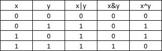
C language also uses logic operators that can work on bits, that’s why they are specifically called bitwise. There are 4 main operators:
-
And &
This operation compares two bit strips and sets logic 1 in any slot where both bits are already set as 1. In all other cases the operator sets a logic 0. -
Or |
This operation compares two bit strips and sets logic 1 in any slot where at least one bit is set as 1. In all other cases the operator sets a logic 0. -
Not ~
This operation transforms the chosen bit strip inverting its set logic values. What was 1 becomes 0 and viceversa. -
Xor ^
This operation compares two bit strips and sets logic 1 in any slot where both bits have the same logic value. In all other cases the operator sets a logic 0.
Here’s a grid that shows the results if we use this operators on two given values (x and y):
TERMINAL
With Linux the toolchain was very simple to set up. Then I did this:
-
cdinto the folder where the source code and Makefile are. -
run
maketo compile the source code and obtain a hex file and a out file. -
run
make program-usbtinyso that AVRDUDE can flash the source code into the microcontroller’s memory.
Group assignment - Compare other architectures
For this group assignment, since we used C language on AVR microcontrollers, we tried to use Arduino language and IDE to program an Arduino Uno Board. This kind of boards still have AVR microcontrollers, but it is a first step away from our initial setting. The next step is trying to program ARM microcontrollers, still using Arduino IDE. We will try to update this section as soon as we try more combinations.
First we installed the Arduino IDE, then we set up the IDE. We used the COM3 Port and the Arduino Uno Board. Then we started reading and understanding Arduino basic syntax.
We all wrote individually a source code. Here’s mine:
void setup() {
  //setting the output pin, which is the built-in LED//
  pinMode(LED_BUILTIN, OUTPUT);
}

void loop() {
  //setting the loop function//
  digitalWrite(LED_BUILTIN,HIGH); //turning on the LED//
  delay(1000);                     //setting one second delay//
  digitalWrite(LED_BUILTIN,LOW);  //turning off the LED//
  delay(1000);                     //setting one second delay//
}
I verified and loaded the code into the Arduino board and it blinked!