11. Input Devices
This is the assessment for this module:
Group assignment
- Probe an input device(s)’s analog and digital signals.
Individual assignment
- Measure something: add a sensor to a microcontroller board that you have designed and read it.
Individual assignment
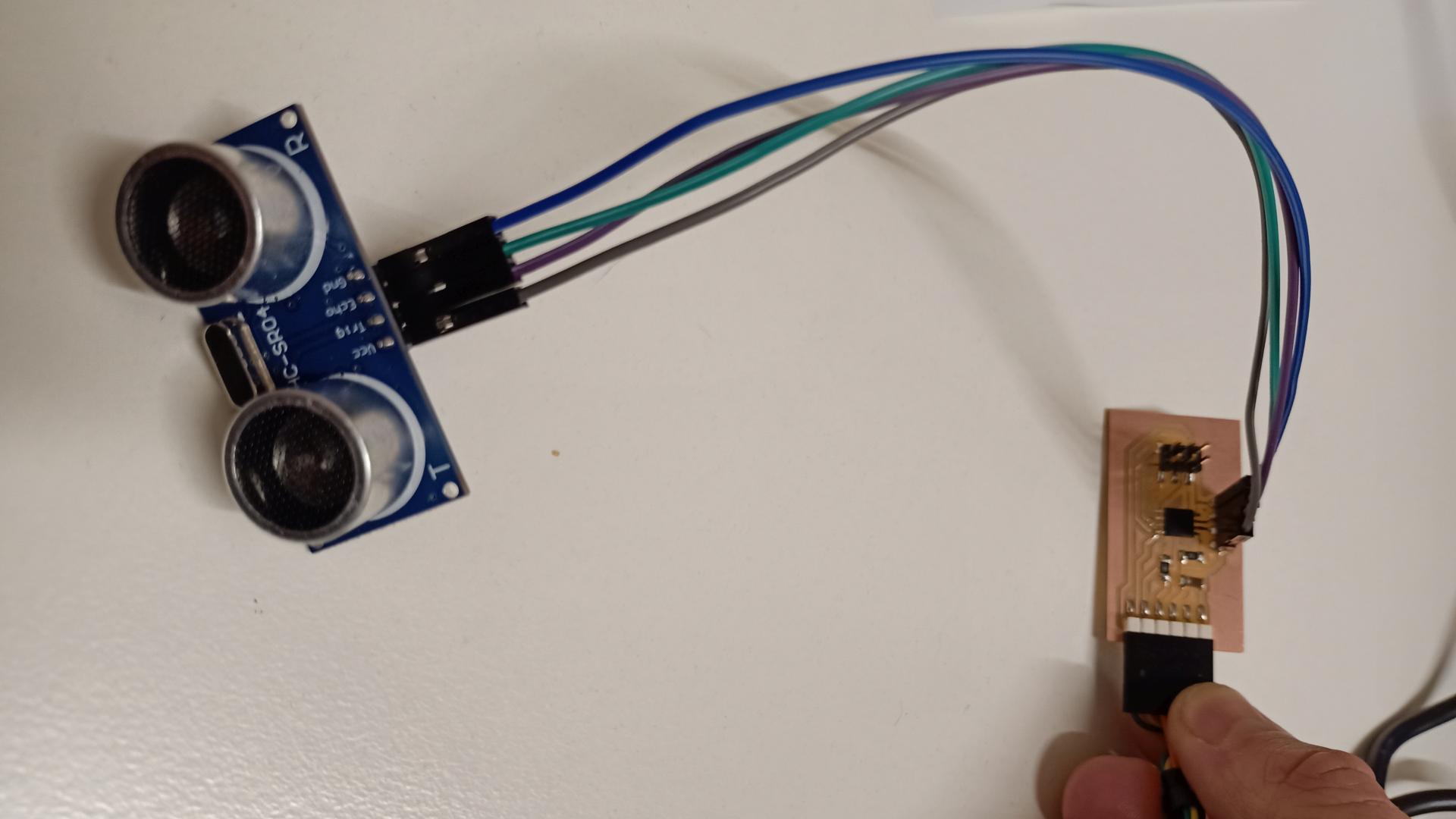
Sonar
Arduino Uno
I decided to try the Sonar as an input device for my next PCB. I found the way it works quite fascinating, probably because I do not have any engineering background, otherwise it would not seem so interesting…
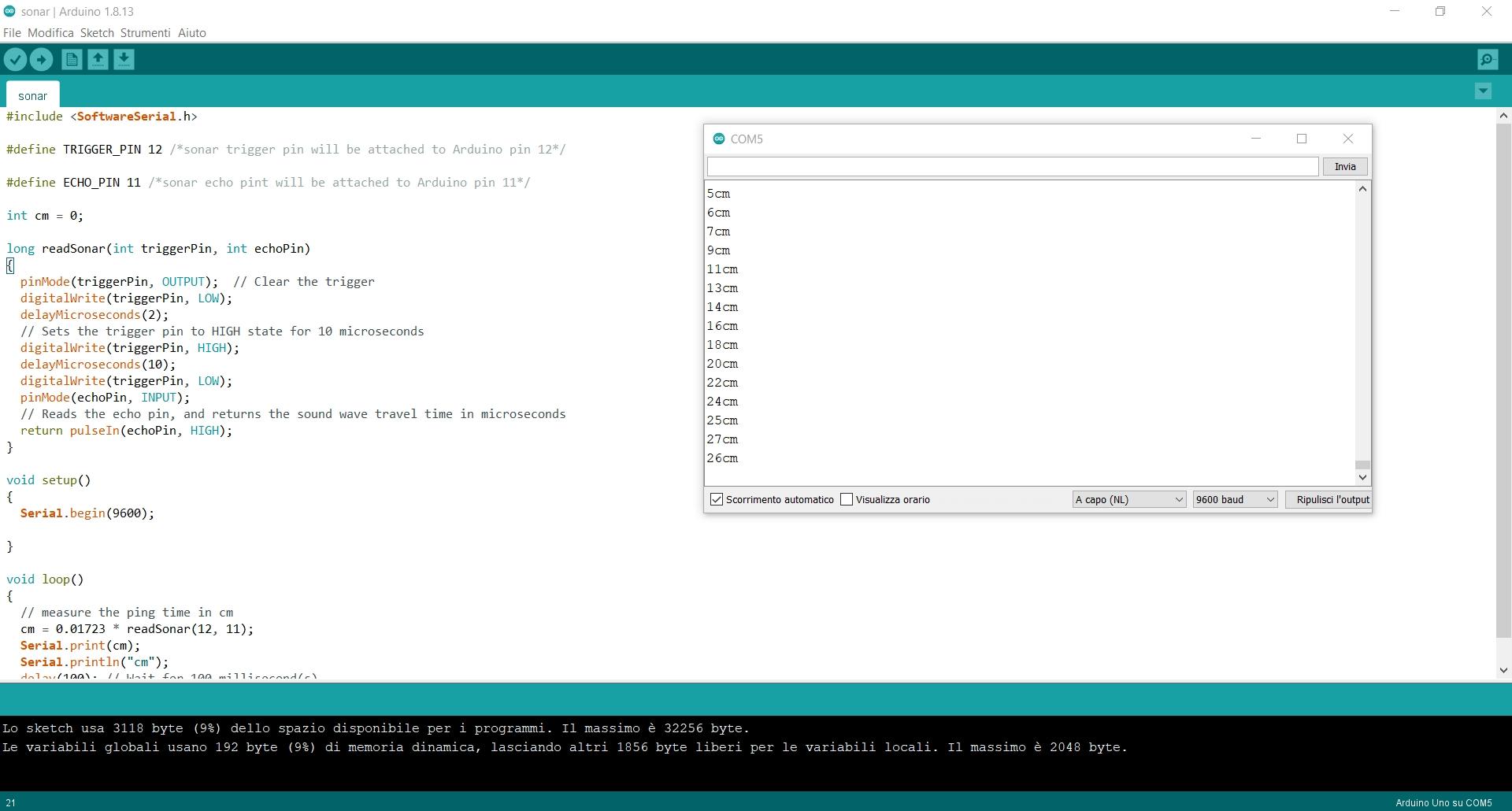
Anyway, I started programming the board on Arduino IDE and before designing my personal brand new PCB on Eagle, I tried the device on a Arduino Uno board, in order to get along with the code, before flashing it on a freshly soldered board.
This is the code I used, taken from the sample on Tinkercad and adapted to my personal scenario:
#include <SoftwareSerial.h>
#define TRIGGER_PIN 12 /*sonar trigger pin will be attached to Arduino pin 12*/
#define ECHO_PIN 11 /*sonar echo pint will be attached to Arduino pin 11*/

int cm = 0;

long readSonar(int triggerPin, int echoPin)
{
  pinMode(triggerPin, OUTPUT);  // Clear the trigger
  digitalWrite(triggerPin, LOW);
  delayMicroseconds(2);
  // Sets the trigger pin to HIGH state for 10 microseconds
  digitalWrite(triggerPin, HIGH);
  delayMicroseconds(10);
  digitalWrite(triggerPin, LOW);
  pinMode(echoPin, INPUT);
  // Reads the echo pin, and returns the sound wave travel time in microseconds
  return pulseIn(echoPin, HIGH);
}

void setup()
{
  Serial.begin(9600);
}

void loop()
{
  // measure the ping time in cm
  cm = 0.01723 * readSonar(12, 11);
  Serial.print(cm);
  Serial.println("cm");
  delay(100); // Wait for 100 millisecond(s)
}
As you can see, the code works properly:
Eagle
Once the code has been tried, it was time to design a new PCB on eagle, to mill it and to solder it.
This is the schematic of my PCB:
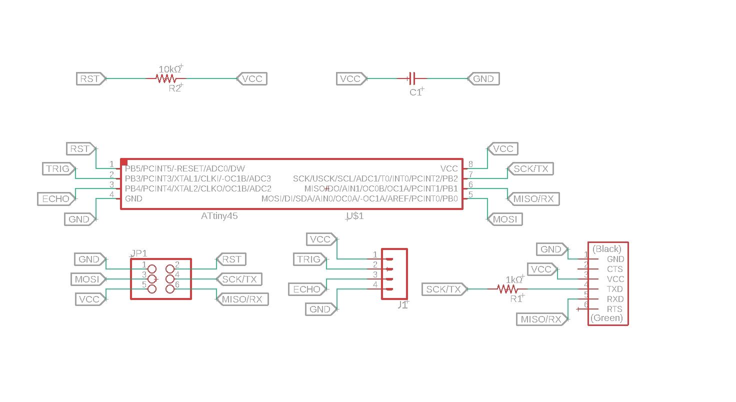
You can download it here
And this is the board of the PCB:
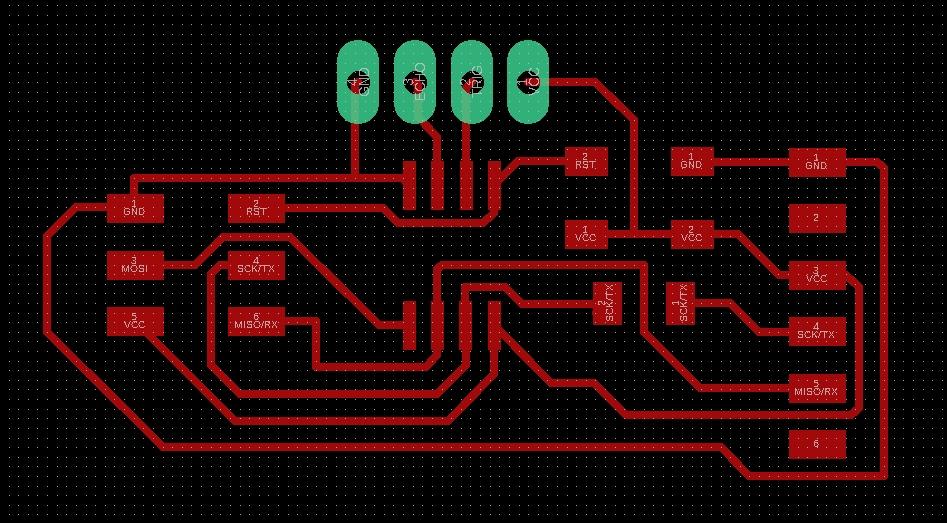
You can download it here
Editing the PNG files
Then I moved on with Photoshop, Mods and next I milled the copper board.
Here it is possible to download the png files I used on Mods:
REMINDER FOR MY FUTURE SELF: DO NOT USE CHROME FOR MODS
I had some problems with the Mods: the holes file did not give me the output I was expecting. It took me a while to understand that it was a browser-related issue rather than a photoshop exporting problem. Google Chrome doesn’t cooperate that much with Mods on my computer.
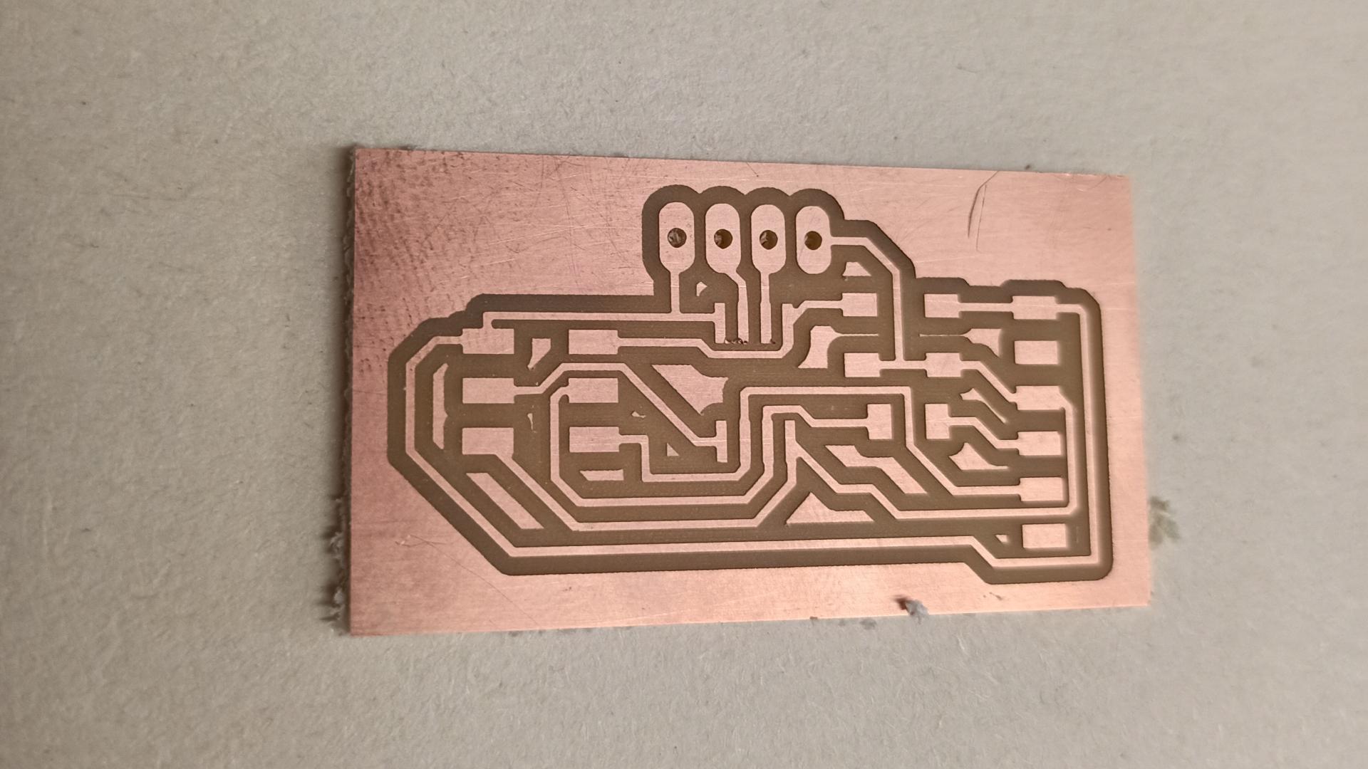
Milling and Soldering
This is the board out of the Roland SRM-20:
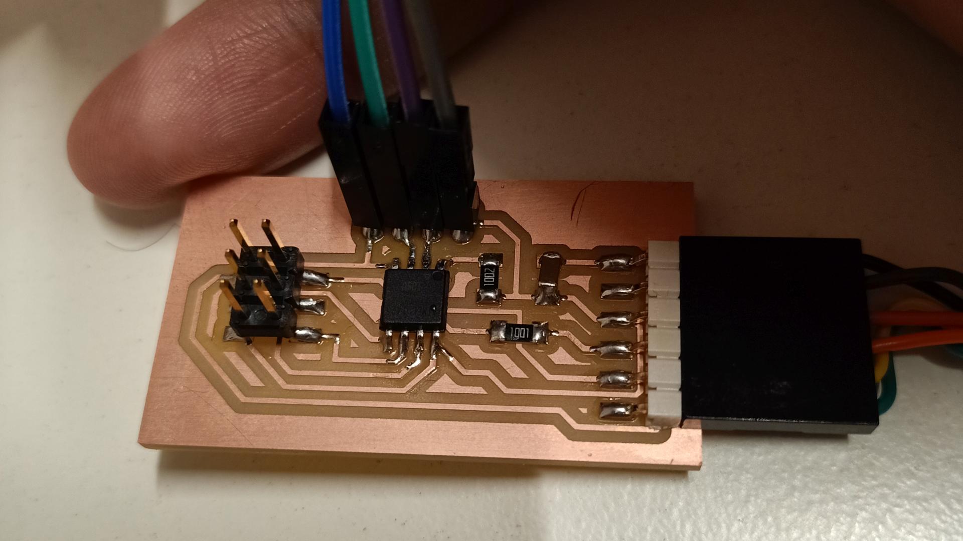
This is the board at the end of the soldering process:

Programming the PCB
Then I Used my USBtiny programmer with the Arduino IDE to burn the bootloader on the new microcontroller. So that at the first flashing of the code the bootloader could grant the whole process. Then, from the second code upload and compiling, it is necessary to program the Board by clicking on the top toolbar sketch>upload using programmer. Since we deleted the bootloader in order to get more memory available, it is not possible anymore to use the compile button on top left corner of the IDE.
At first my computer did not recognize the USBtiny, so I had to install the drivers from Adafruit.
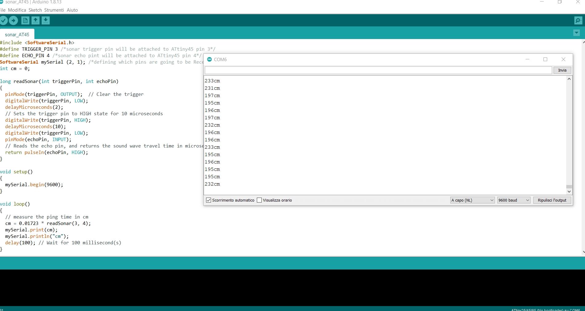
This is the code I used for my PCB:
#include <SoftwareSerial.h>
#define TRIGGER_PIN 3 /*sonar trigger pin will be attached to ATtiny45 pin 3*/
#define ECHO_PIN 4 /*sonar echo pint will be attached to ATtiny45 pin 4*/
SoftwareSerial mySerial (2, 1); /*defining which pins are going to be Receiver and Transmitter*/
int cm = 0;

long readSonar(int triggerPin, int echoPin)
{
  pinMode(triggerPin, OUTPUT);  // Clear the trigger
  digitalWrite(triggerPin, LOW);
  delayMicroseconds(2);
  // Sets the trigger pin to HIGH state for 10 microseconds
  digitalWrite(triggerPin, HIGH);
  delayMicroseconds(10);
  digitalWrite(triggerPin, LOW);
  pinMode(echoPin, INPUT);
  // Reads the echo pin, and returns the sound wave travel time in microseconds
  return pulseIn(echoPin, HIGH);
}

void setup()
{
  mySerial.begin(9600);
}

void loop()
{
  // measure the ping time in cm
  cm = 0.01723 * readSonar(3, 4);
  mySerial.print(cm);
  mySerial.println("cm");
  delay(100); // Wait for 100 millisecond(s)
}
And as you can see, it works!
RFID
Arduino Uno
Since I currently planned to use this tag reader in my final project,, I decided to give it a go with an Arduino Uno Board.
Using the Arduino IDE, I found the instructions about the pinout and the code on this site. Of course I read the code, its library (along with my instructor) and tried to make it mine.
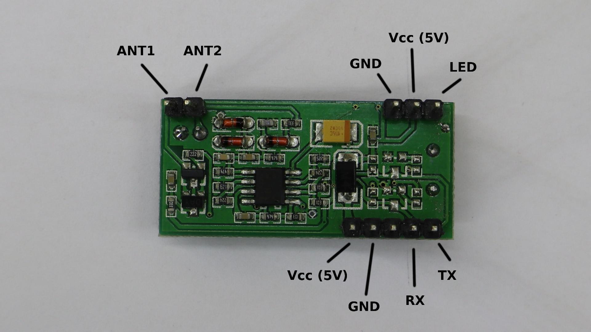
This is the pin layout for the RDM6300, the RFID scanner I used:
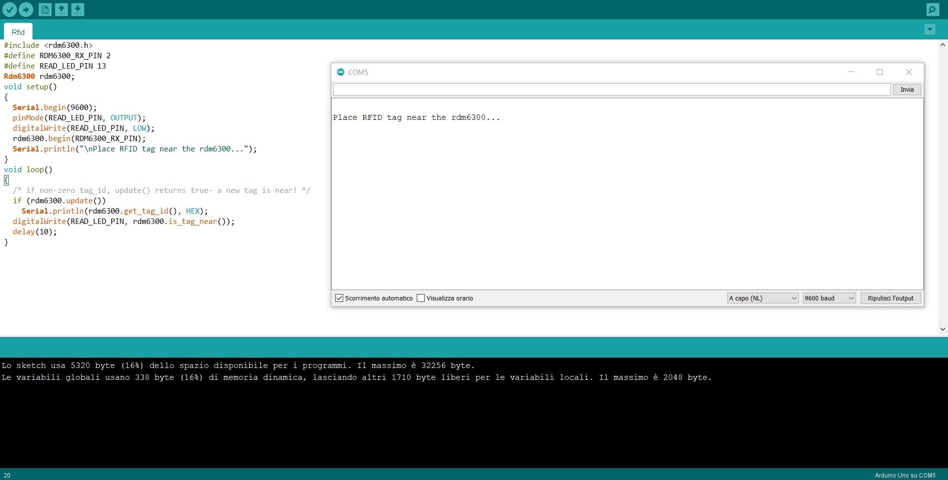
Here’s the code I used:
/*Defining the necessary pins for the RFID and including the library. Then update the system so that RDM6300 and rdm6300 are aligned as one.*/
#include <rdm6300.h>
#define RDM6300_RX_PIN 2
#define READ_LED_PIN 13
Rdm6300 rdm6300;

void setup()
{
/*Initialising the serial monitor and the RFID scanner, the LED will stay low and the phrase "RFID rdm6300 waiting for tag..." will be shown until the reader identifies a tag.*/
  Serial.begin(9600);
  pinMode(READ_LED_PIN, OUTPUT);
  digitalWrite(READ_LED_PIN, LOW);
  rdm6300.begin(RDM6300_RX_PIN);
  Serial.println("\nRFID rdm6300 waiting for tag...");
}

void loop()
{
/*If the reader scans a tag, the serial monitor will show its ID, the LED will turn on as far as the tag is still there.*/
/*If non-zero tag_id, update() returns true- a new tag is near! */

  if (rdm6300.update())
    Serial.println(rdm6300.get_tag_id(), HEX);
    digitalWrite(READ_LED_PIN, rdm6300.is_tag_near());
    delay(10);
}
The problem I had, which I am going to deal with in the next weeks, is that the RFID repeats the Tag’s ID even if I don’t change it. Every time the reader identifies it as new and writes it on the Serial monitor. I would like to avoid repetitions, so that the terminal could show only as many lines as the amount of tags I used.
Group assignment
Since the input sensors I’ve chosen are not so easy to measure, because they send data without any interruption. I tried to measure the sensors used by other students in this lab.
More specifically, I tried to measure the voltage variation of a thermistor. This tiny sensor reduces the intensity of its signal at the same pace temperature goes up. I used the bench power supply and the oscilloscope in order to measure the variations. Since the thermistor did not feel so much difference using my fingers, I wanted to use the desoldering station in order to reach higher temperatures.
This is what the oscilloscope showed me:
The signal input moves up if the temperature gets lower and viceversa. I found this process quite understandable.