4. Electronics Production
This is the assessment for this module:
Group assignments
- Characterize the design rules for your PCB production process: document feeds, speeds, plunge rate, depth of cut (traces and outline) and tooling.
- Document your work (in a group or individually).
Individual assignment
- Make an in-circuit programmer by milling and stuffing the PCB, test it, then optionally try other PCB fabrication process.
PCB milling - group assignment
You can find the documentation about week 4 group assignment here.
PCB milling - Individual assignment
This week I have to create a PCB from a chosen PNG and mill it with the machine.
I’ve never worked before with a milling machine and it seems really fragile…fingers crossed.
SPOILER ALERT: At the first attempt I damaged the drilling bit’s housing. All the settings were correct but the bit was not properly secured (the hold wasn’t tight).
Once you have prepared all your cutting files for the machine, it’s time to set the machine.
Mods
Our machine is (or should I say was?…)a Roland SRM-20. So this is are the following steps:
- Open the mods page
- Right click anywhere on the screen and select programs > open server programs > Roland > SRM-20 > PCB png
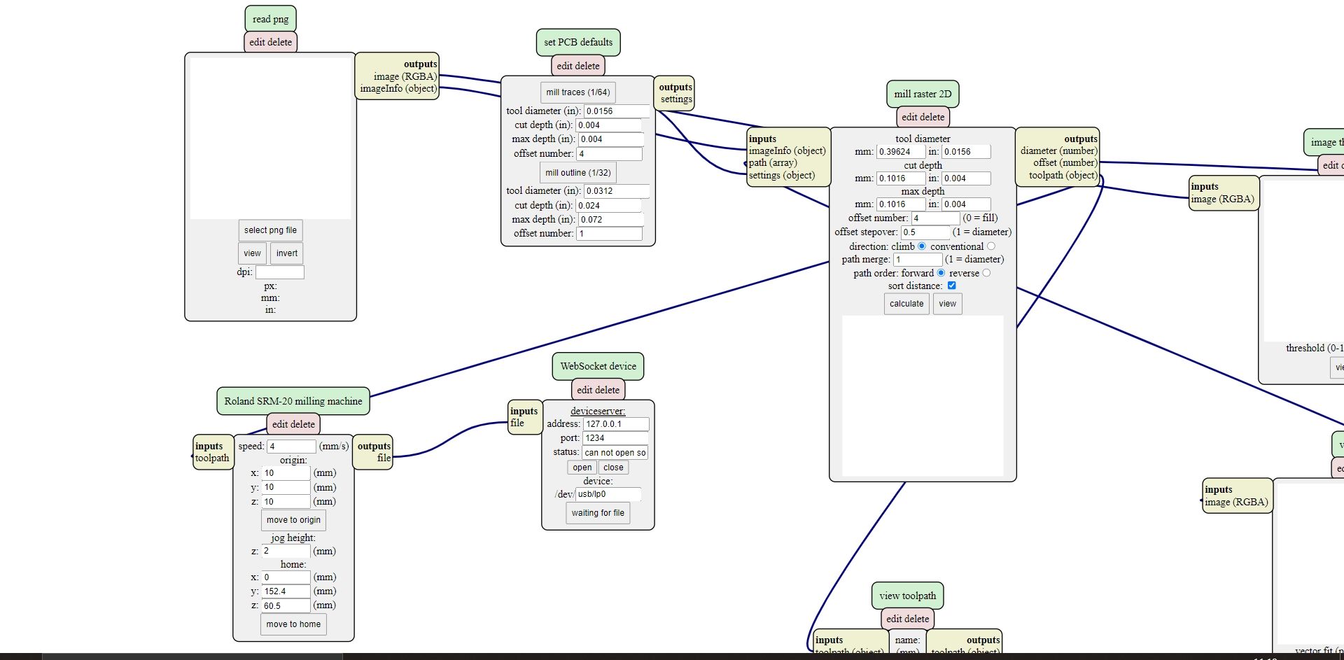 )
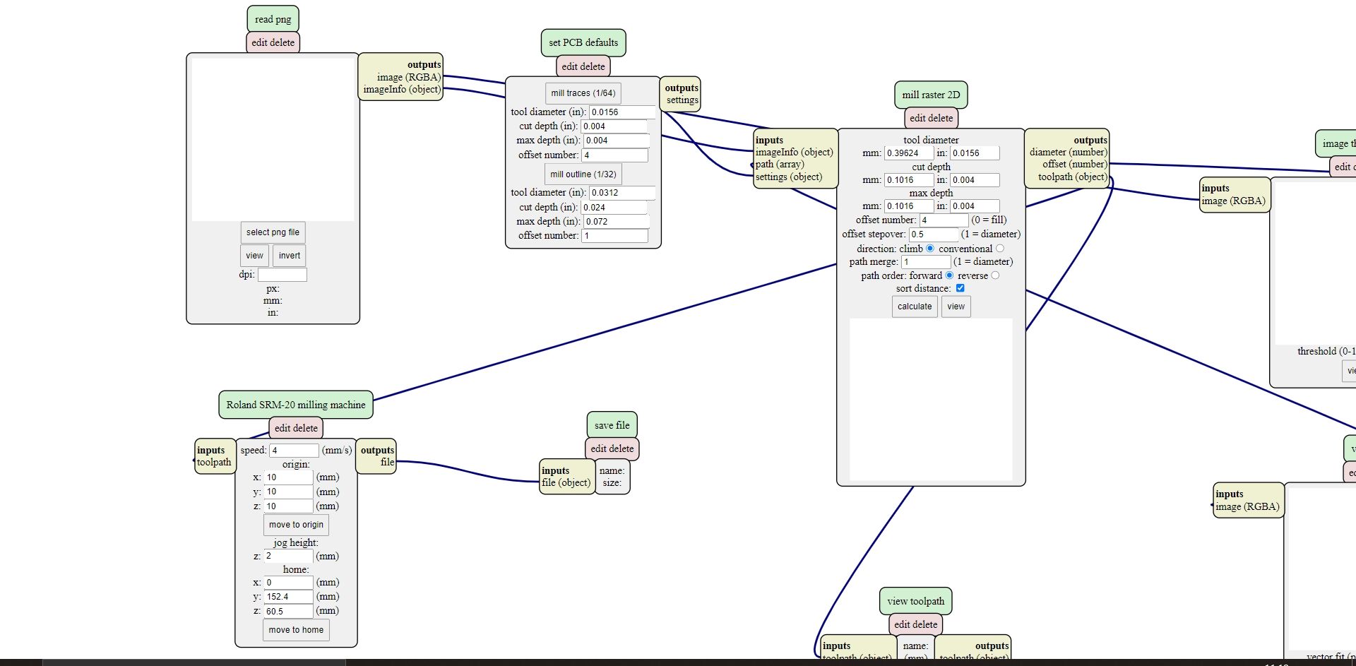
- Since Mods presumes that you’re working on a computer which is connected with the milling machine, remove the websocket device module.
- Once the previous module has been removed, replace it with a save file right clicking anywhere on the screen and select module > open server modules > file > save.
)
- Since Mods presumes that you’re working on a computer which is connected with the milling machine, remove the websocket device module.
- Once the previous module has been removed, replace it with a save file right clicking anywhere on the screen and select module > open server modules > file > save.
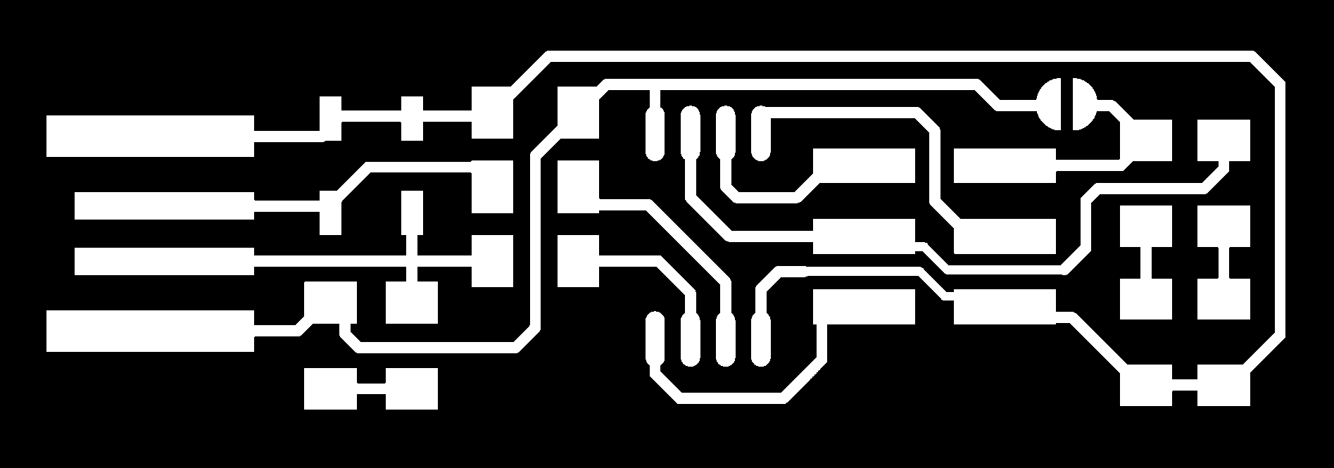
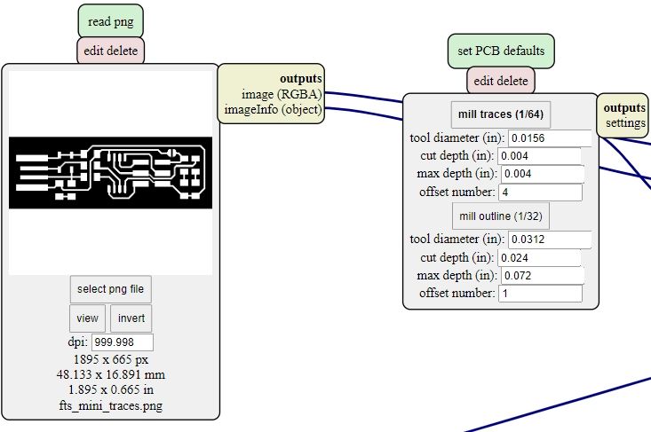
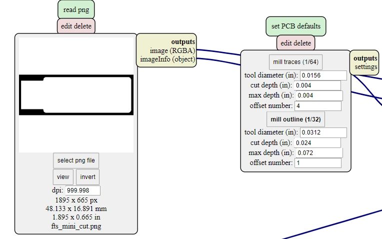
- Load the chosen png file and check the DPI value, it must be 1000 or more.
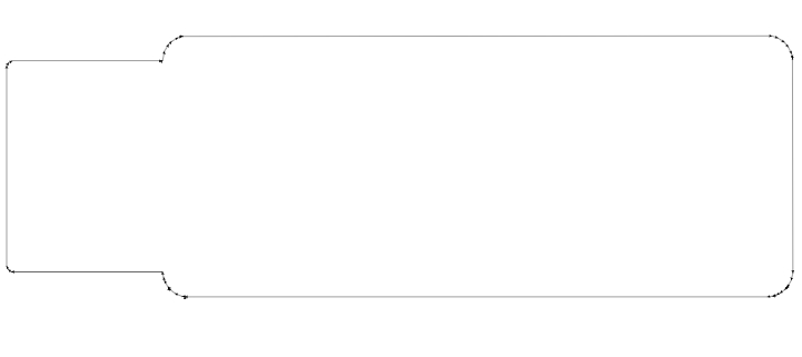
This are the png files I’ve downloaded from the previously done work:

- If you’re working on the PCB’s traces, you must select the 1/64 settings on the next module.
- If you’re working on the PCB’s cutting line, you must select the 1/32 settings on the next module.
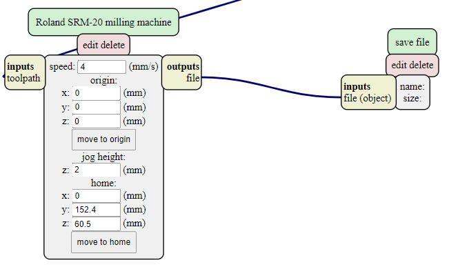
- Next to the save module there is a setting module that directs the Roland SRM-20, for both png files it is important to set the XYZ origin point to 0-0-0. All the other settings can remain unchanged.
- On the mill raster module double check the values if they correspond to the values on the PCB defaults. The other values usually remain unchanged, on this particular case I had to change the offset value from 4 to 5.
- When all the settings are ready, click on the calculate button in order to save a rml file. This file will tell the machine how to work.
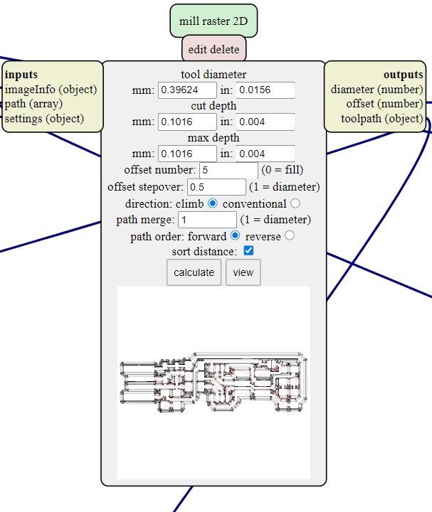
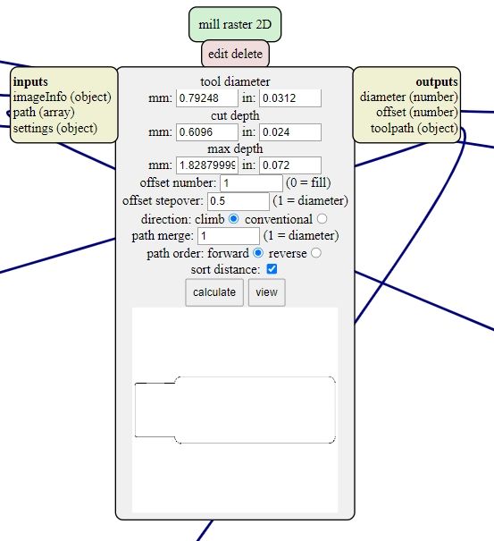
- The browser will also load a preview of the milling process (a toolpath). Double check if the png and the rml file look the same.
It’s time to move on the milling machine!
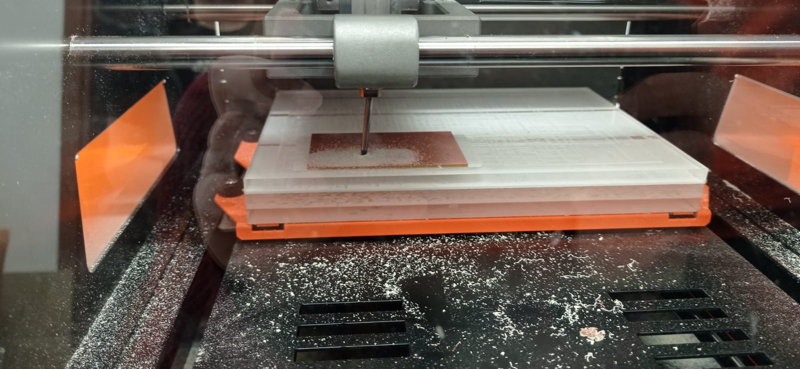
Roland SRM-20
First, I placed the 1/64 inch drilling bit, then I fixed the copper plate on the sacrificial surface. Working with the software, I placed the origin point on X and Y axes. Then I got as close as possible to the surface and made the drill bit gradually reach it. Then I told the software to set the new origin point on the Z axis. I raised the bit 2mm and launched the cutting process.
I was expecting the machine to start cutting differently so when it started from another point rather than the origin I freaked out and stopped the machine. The copper plate got ruined in that place so I had to move the origin on another point. I did not hold tight enough the drilling bit to its housing so when I launched the cutting process everything seemed fine for a while. But then the drill bit lost its grip and got stuck in the sacrificial surface.
It took a while to restore the mill machine, but then I succeeded. The third attempt did the job.
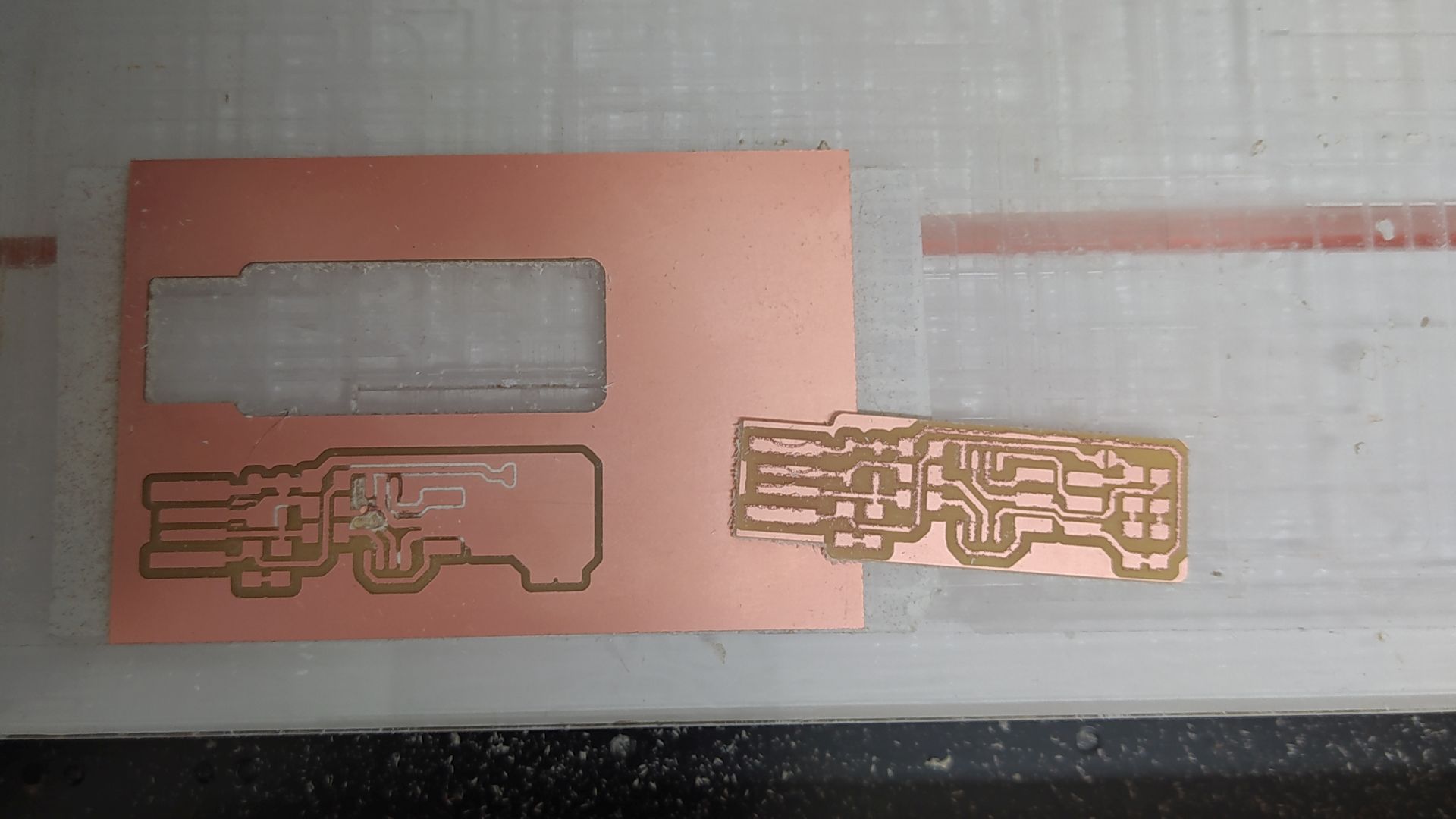
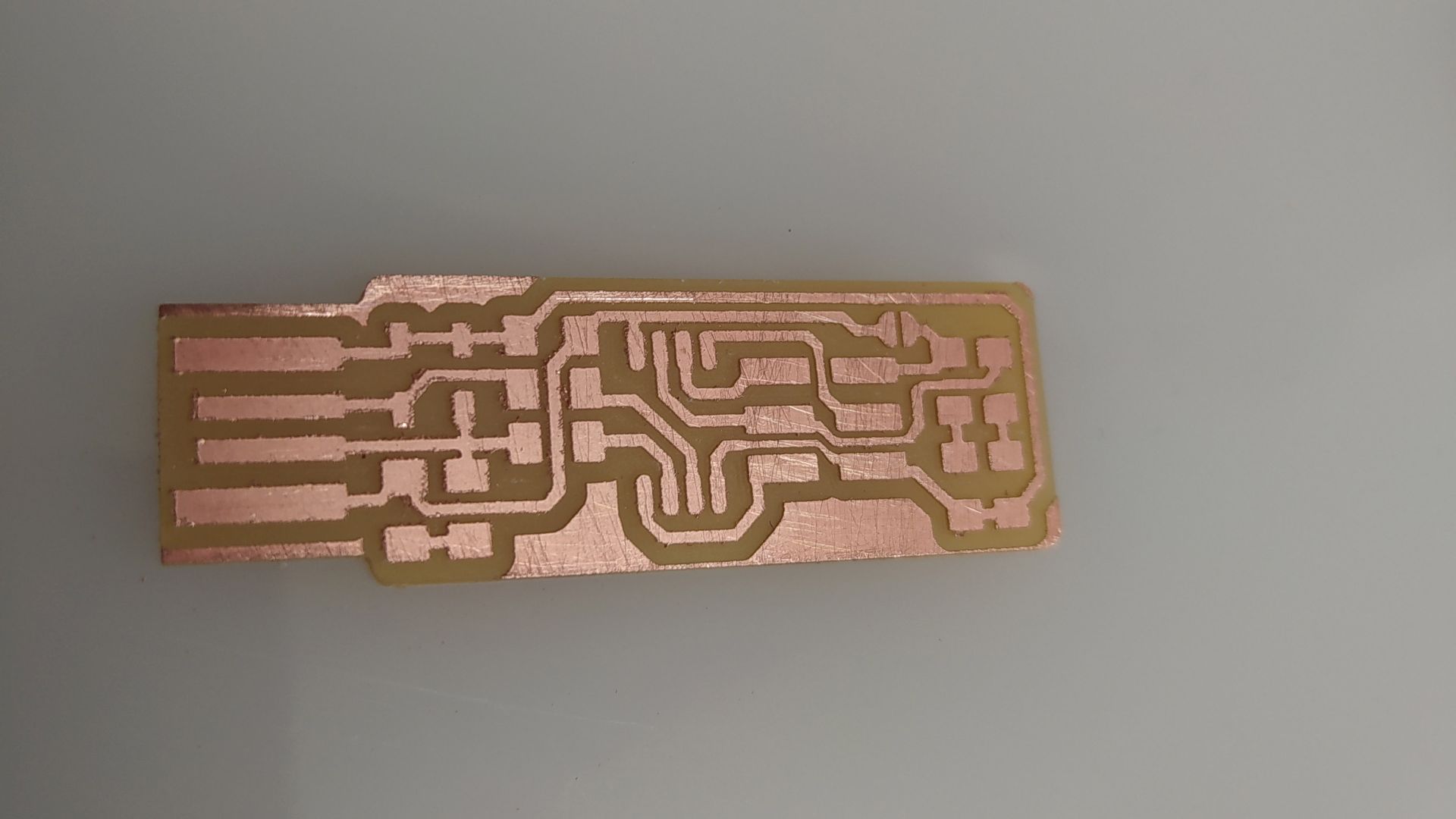
The PCB needed some sandpaper because the drilling bit was quite worn out. This is the milling process’ final result.
Soldering
Learning the basics
The instructor taught us the basics:
- Turn on the solder and keep it to 330 °C.
- Clean the tip every time with the sponge or the brass wire.
- The fume extractor must always be on while working.
- Fix the PCB to the surface while you are soldering, so it won’t move accidentally.
- Prepare a bill of materials so that all the necessary items are next to you when you need them and you can’t forget a piece.
- Take the multimeter next to you, so that traces and components’ conductivity can be tested.
- In case you solder too much wire on the components, use the copper braid to remove the unnecessary parts.
- Keep the soldering grease close to you, it can be used to facilitate the soldering process guiding the wire on the traces.
- Solder few wire on the trace in order to stick the component to the board simply reheating the tin when the component is ready to be fixed.
- Once the component has been fixed to the pcb, solder the remaining pins.
- The tin must be as shiny as possible, to do so the soldering tip must be hot and not ruined.
- Always use the tweezers to hold the components while soldering.
Assignment for this week
This week’s task is to choose a In-programmer from this list, take note of all the components and to solder them. Once the soldering process is done, program it and test it.
Choosing the in-circuit programmer
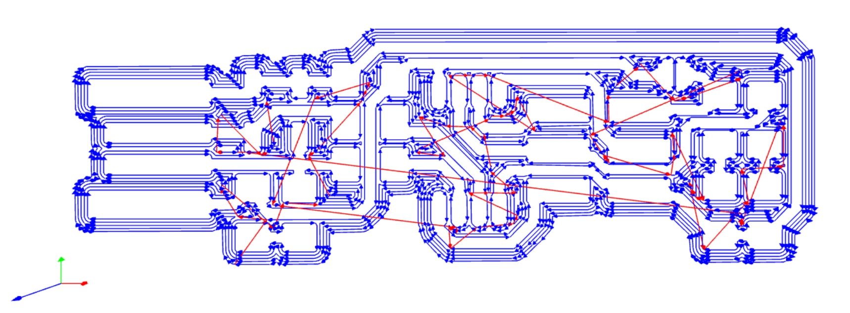
Looking on the previous list, I decided to make an ATtiny45 ISP, more specifically: this one.
Its documentation seemed great and the form factor looked interesting.
Here it is possible to see the structure of all the components:
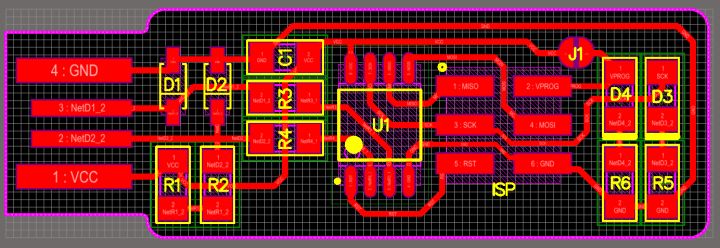
Gathering the materials
This are all the components I soldered on the PCB:
- 1x ATtiny45 or ATtiny85
- 2x 1kΩ resistors
- 2x 499Ω resistors
- 2x 49Ω resistors
- 2x 3.3v zener diodes
- 1x red LED
- 1x green LED
- 1x 100nF capacitor
- 1x 2x3 pin header
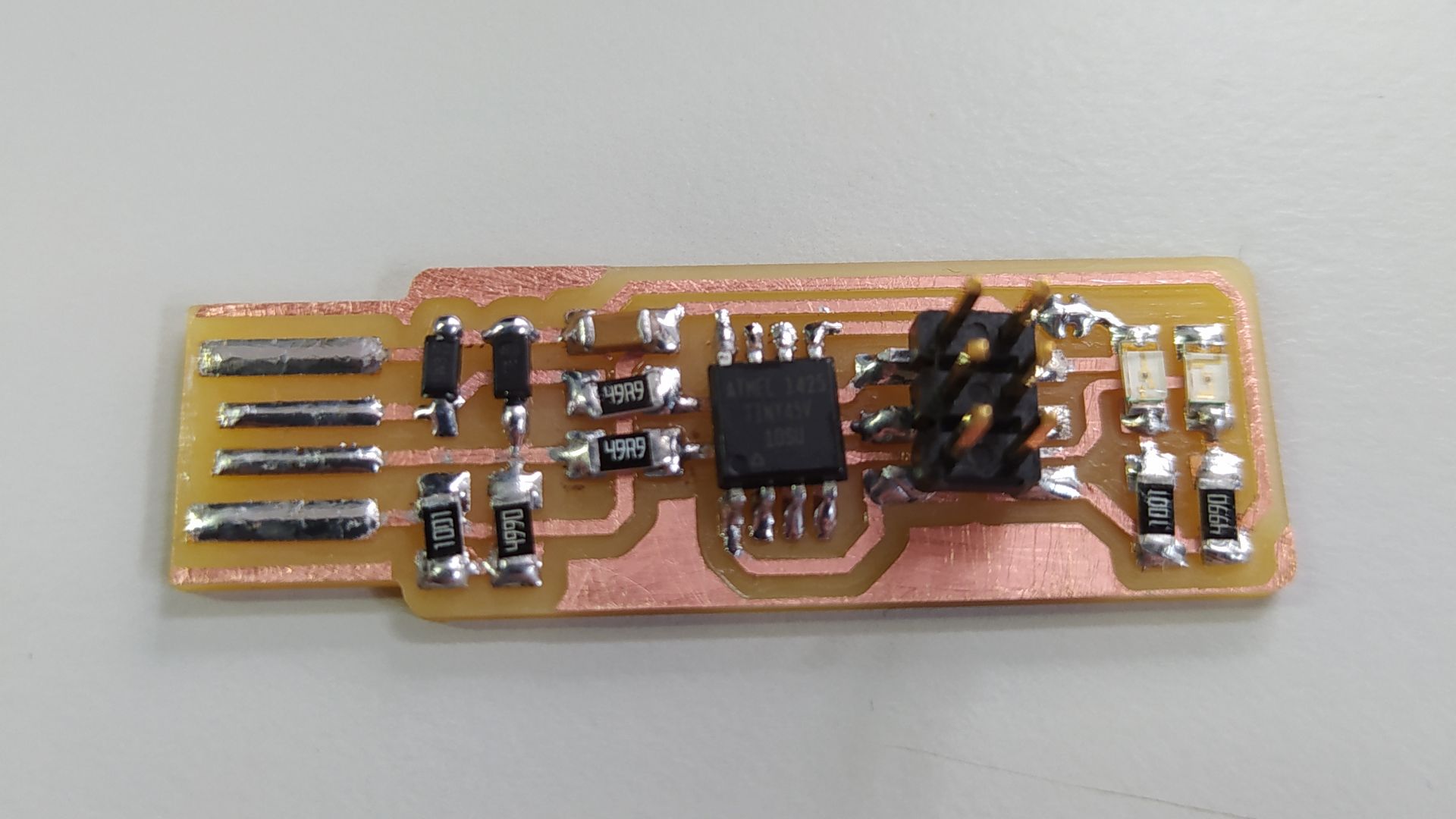
Soldering process
Looking at the scheme, it took me an hour to solder all the components. Since this is my first attempt I’m rather satisfied.
Debugging
Once the soldering process was over, I checked all the possible connections with the multimeter and everything worked out.
After the multimeter test it was time for the smoke test, which went smoothly as well.
Programming
I used a PC where all the toolchain was previously installed, so I did not have to do the whole process. Once the firmware was ready, through the terminal it was possible to program the PCB through a commercial programming board. The process ran smoothly, at the end the board also replied with a “thank you”…I was not expecting such kindness from a PCB.
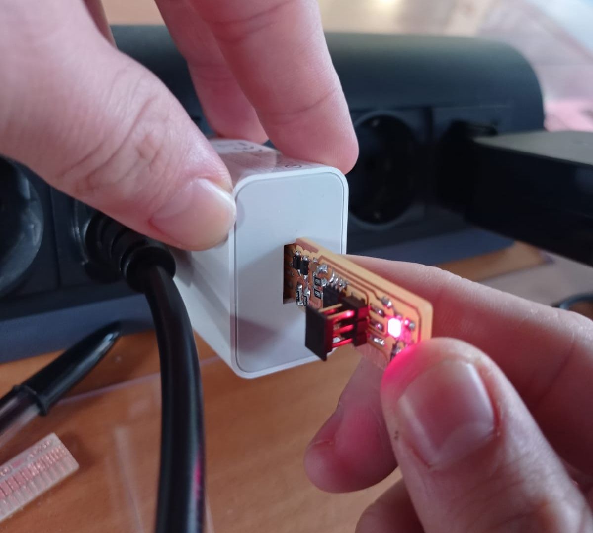
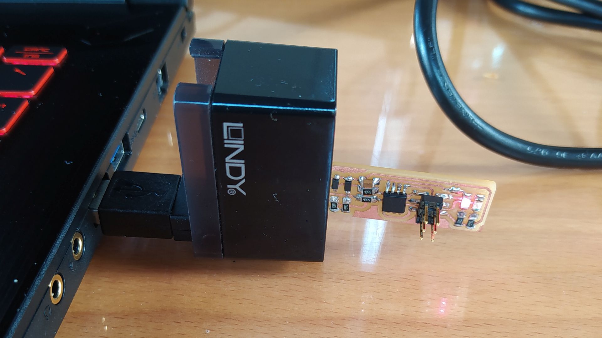
Testing
It was time to check if the newly-programmed board could be recognized by my PC. Initially the instructor’s PC did not see it on the USB devices list, so we double checked on another machine and fortunately the board was visible! Just to be more sure, I triple-checked on my PC, and the ISP was visible.
Looking at the documentation, there should be another step after the programming process: blow the reset fuse in order to disallow any future reprogramming on the process.
Moreover the instructor told me to keep the bridge on the solder jumper, so that the ISP can supply energy to the boards it is going to program. The USB energy is more than sufficient for two boards.
This is the end of the documentation.
Update: March 12th - Programming the PCB on my own.
Since I had to learn how to program completely on my own during the embedded programming week, I decided to re-program the USBtiny. This has been possible because at first I did not run the make rstdisbl command. Looking at previous years’ documentation, installing the toolchain on windows 10 is way more complex than other operating systems. That’s why I decided to prepare a second machine (an old netbook) with Linux Mint. I used this tiny netbook for programming my ATtiny45 as a programmer, and I think I’ll keep using it for the following programming weeks.
So here’s what I did, following Brian’s brilliant documentation:
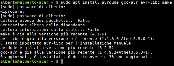
- I installed the toolchain through the terminal.
- I downloaded the firmware.
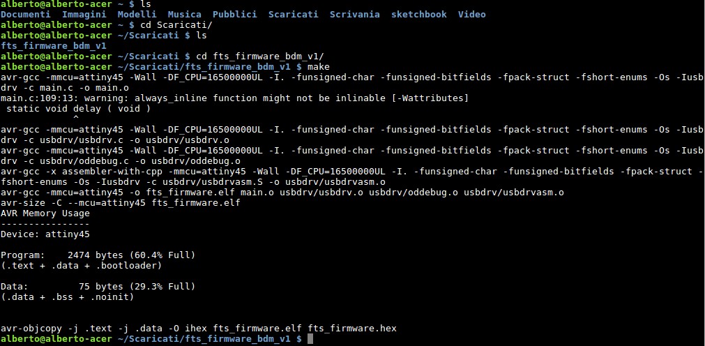
- I opened the terminal again and changed directory moving into the firmware folder.
- Then I ran
make, in order to obtain a hex file into the same folder.
- I did not change anything into the makefile, since I am using a USBtiny as Brian did.
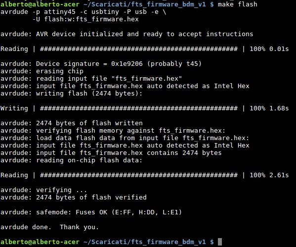
- Still into the firmware folder, I ran
make flashso that the hex file could be installed in the USBtiny’s Flash memory.
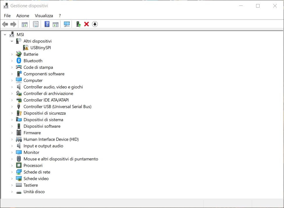
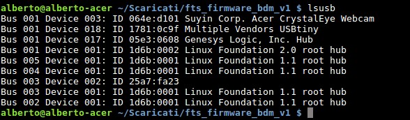
- Once the program has been installed, I had to check if the USBtiny could be seen by the PC. Still through the terminal I ran
lsusband checked if there was a Multiple vendors USBtiny. Everything worked, the Pc saw the programmer.
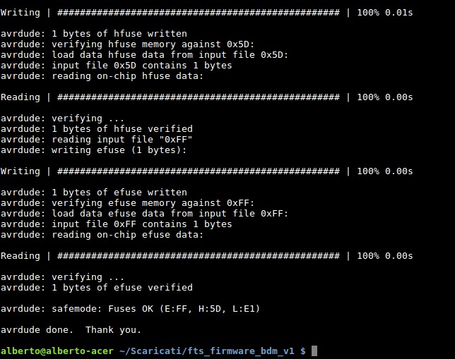
- The last thing I did, in order to be sure that the programmer could not lose its programming function through the reset pin from now on, I blew the reset fuse. This has been possible running the
make rstdisblcommand. Everything worked properly. The programmer is ready to create other boards!
End of the update.