2. Computer-Aided Design
This week I worked on modeling the sketch of my final project
This is the assesment for this module:
- Model (raster, vector, 2D, 3D, render, animate, simulate, …) a possible final project, compress your images and videos, and post it on your class page
I had to choose among a list of softwares for 2D and 3D modeling, pick a couple of each category and see how they go. Honestly, I have to see how bad I do with all of them.
2D softwares
INKSCAPE
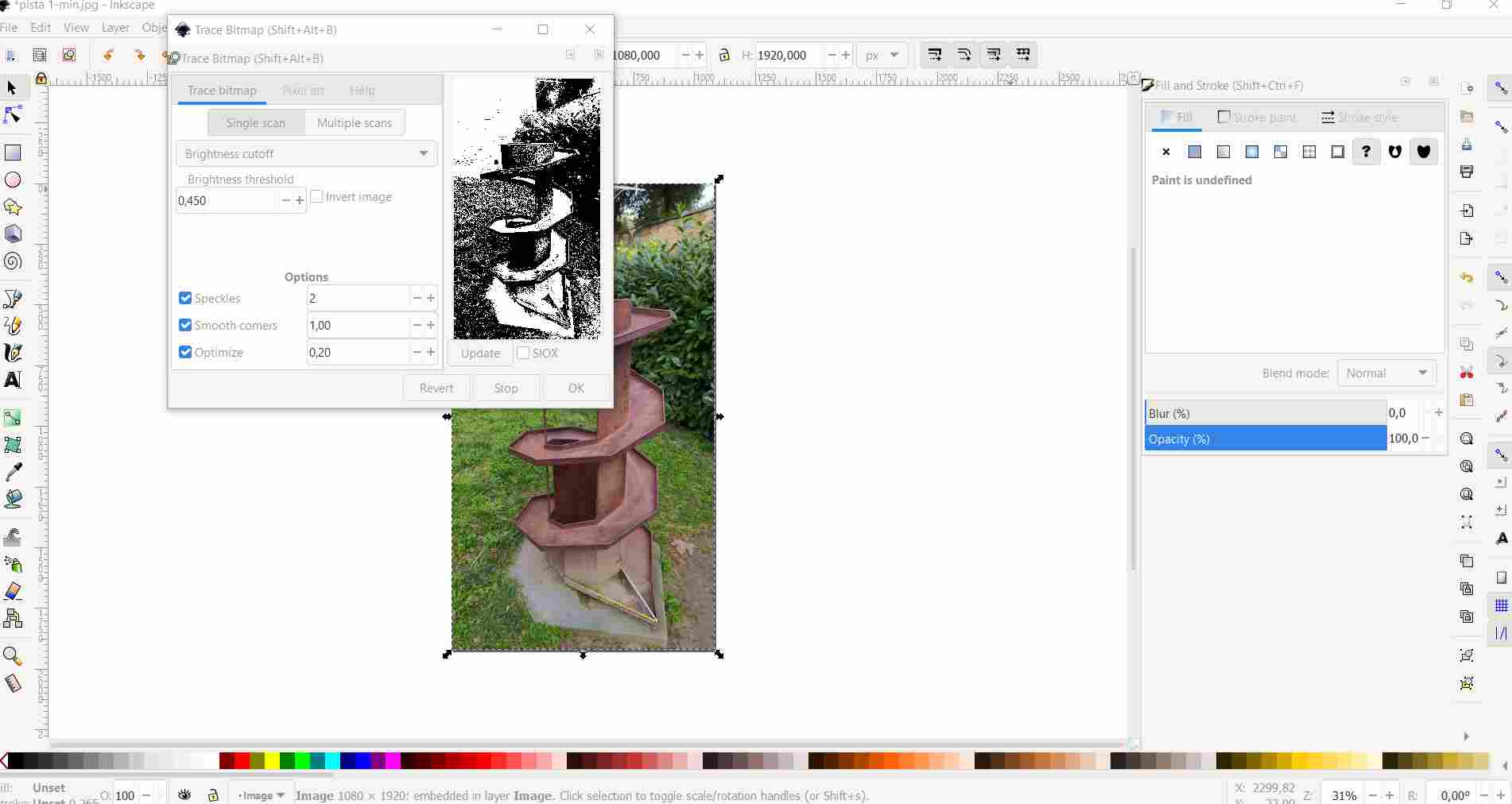
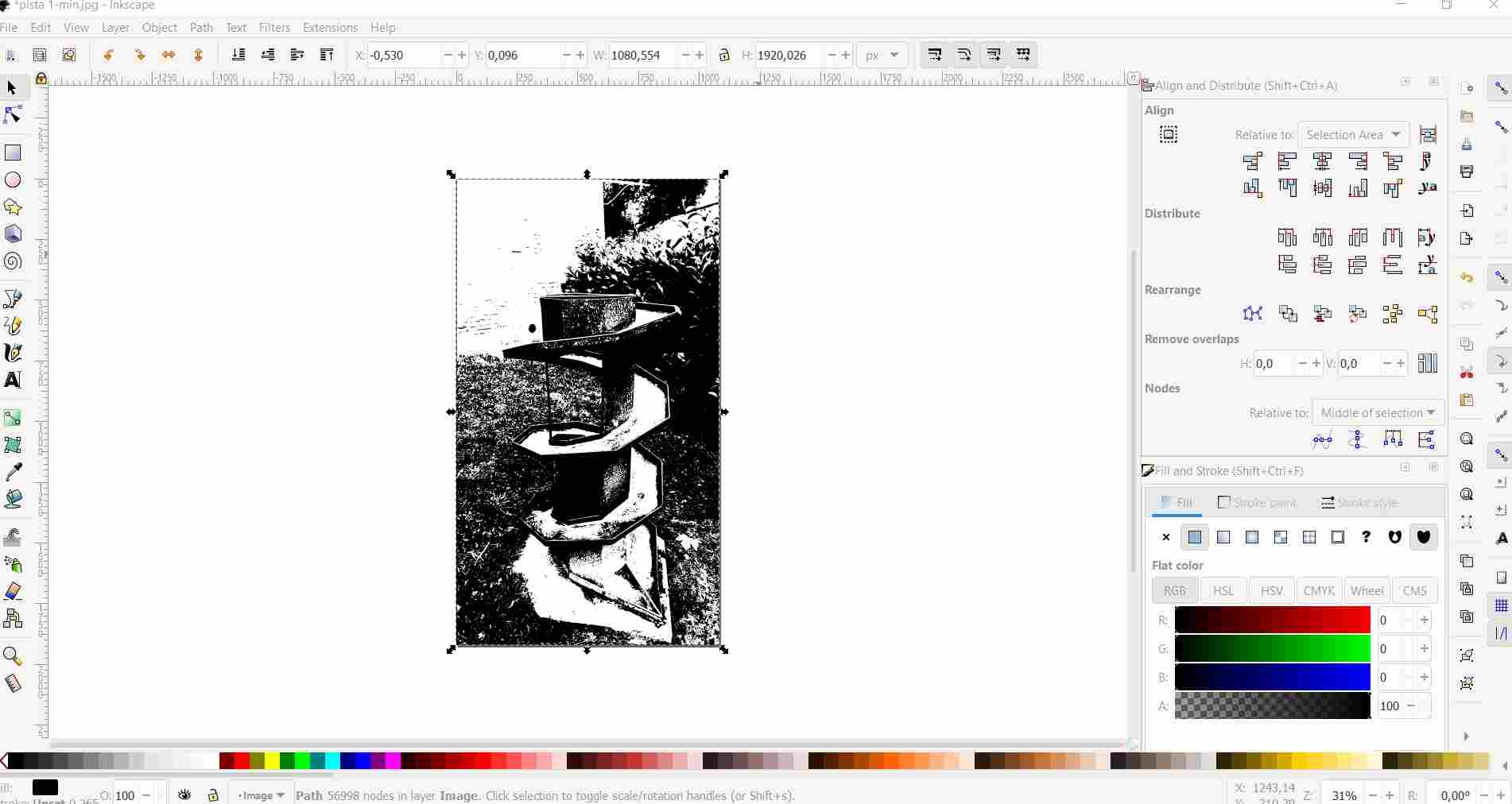
Since I am changing my final project, I had to redraw the sketch for week 1 task, then I moved to Inkscape in order to trace the bitmap of a few pictures of a starting idea.
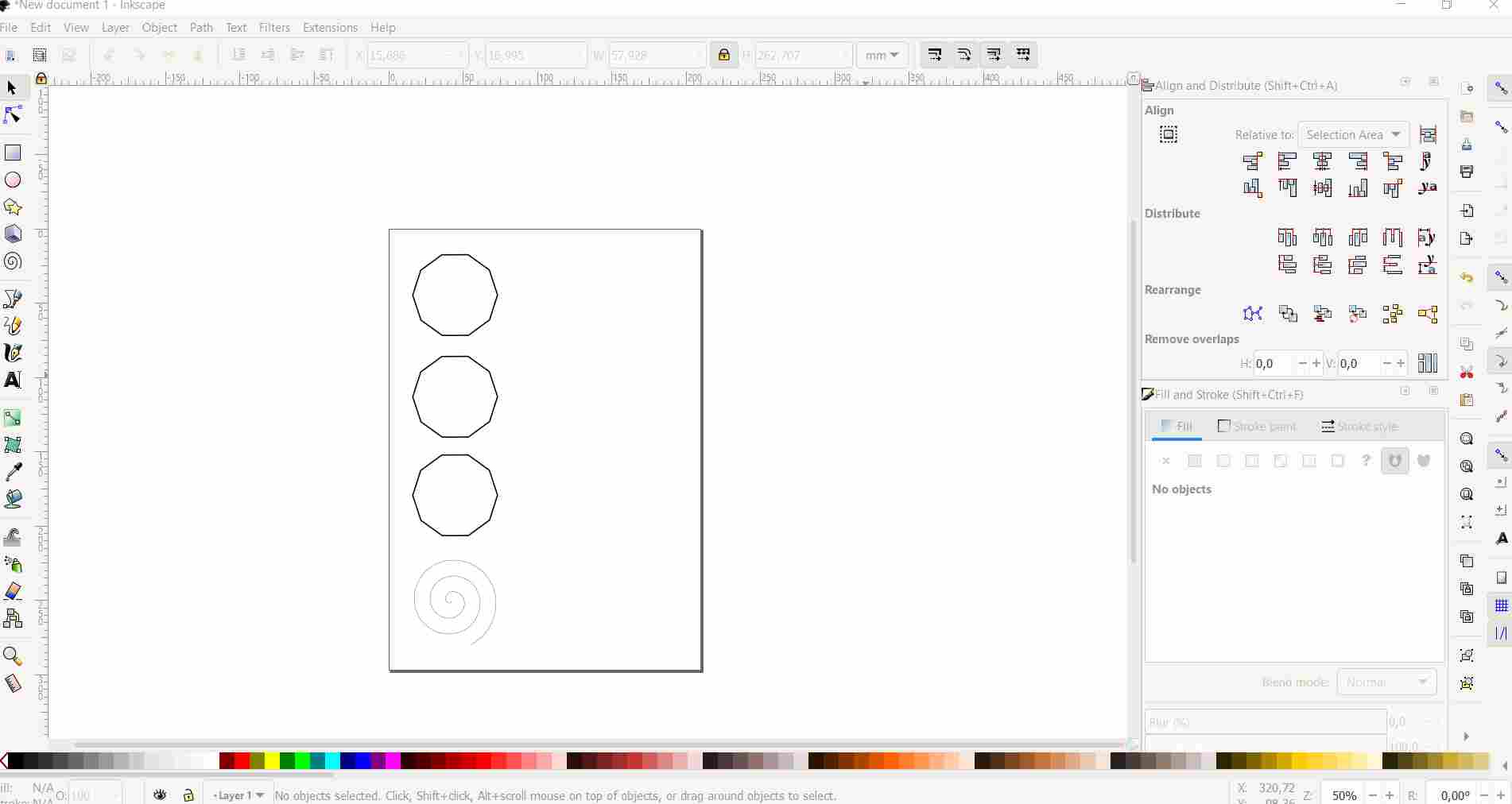
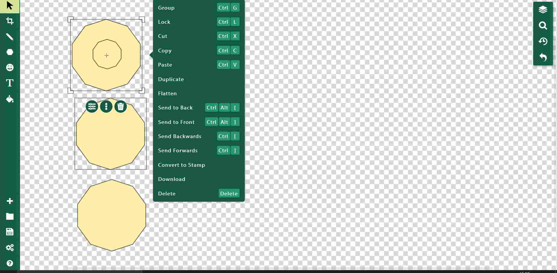
Then I started using Inkscape from zero, creating shapes so that the basic structure can be seen in 2D. I wanted to create a sort of manual with the shapes and some text that explain every element. So first I created three decagons and a spiral (press f9 to obtain the spiral creator tool), aligning them vertically on the left with the “Align and distribute” toolbar (shift + ctrl + A).
Then I added some text in order to explain the items and the project.
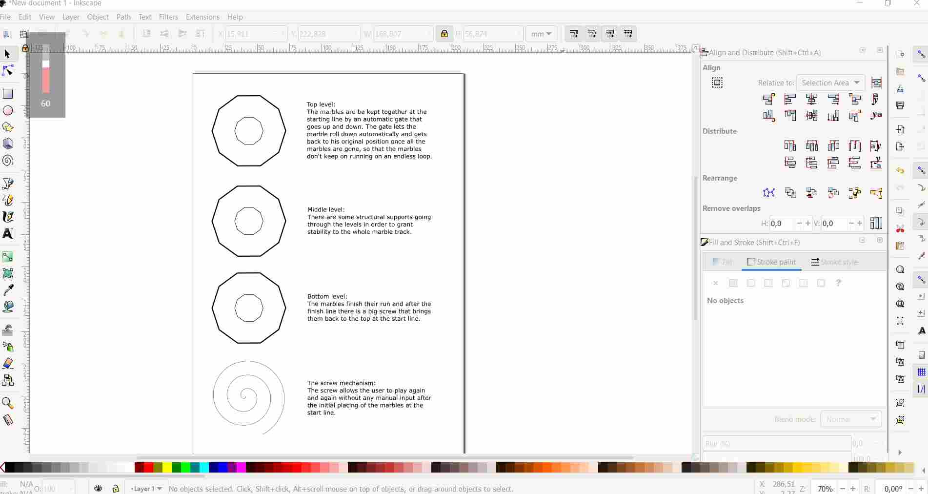
The last thing that I did is aligning the text to each shape.
SKETCHPAD
I wanted to try another tool. Sketchpad works completely online. I’ve never used it before. Creating geometrical objects seems easy, but I can’t find the aligning settings. I checked the online guide but still I did not find any mention to alignment.
Then I kept using the lines, the paths, some arrows and small circles so that the purpose of the marble track could be explained.
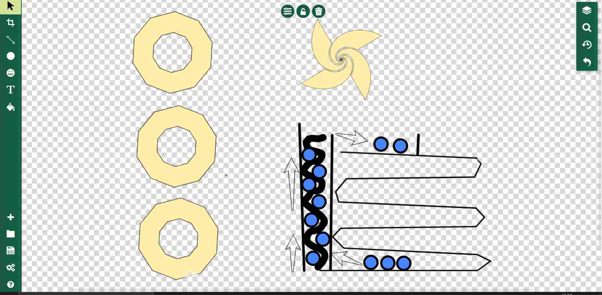
I know, I’m so bad at drawing with the mouse.
Then I saved the svg file of this work with sketchpad. They both output a svg file, but I prefer the schematic approach used by Inkscape rather than Sketchpad.
PHOTOSHOP
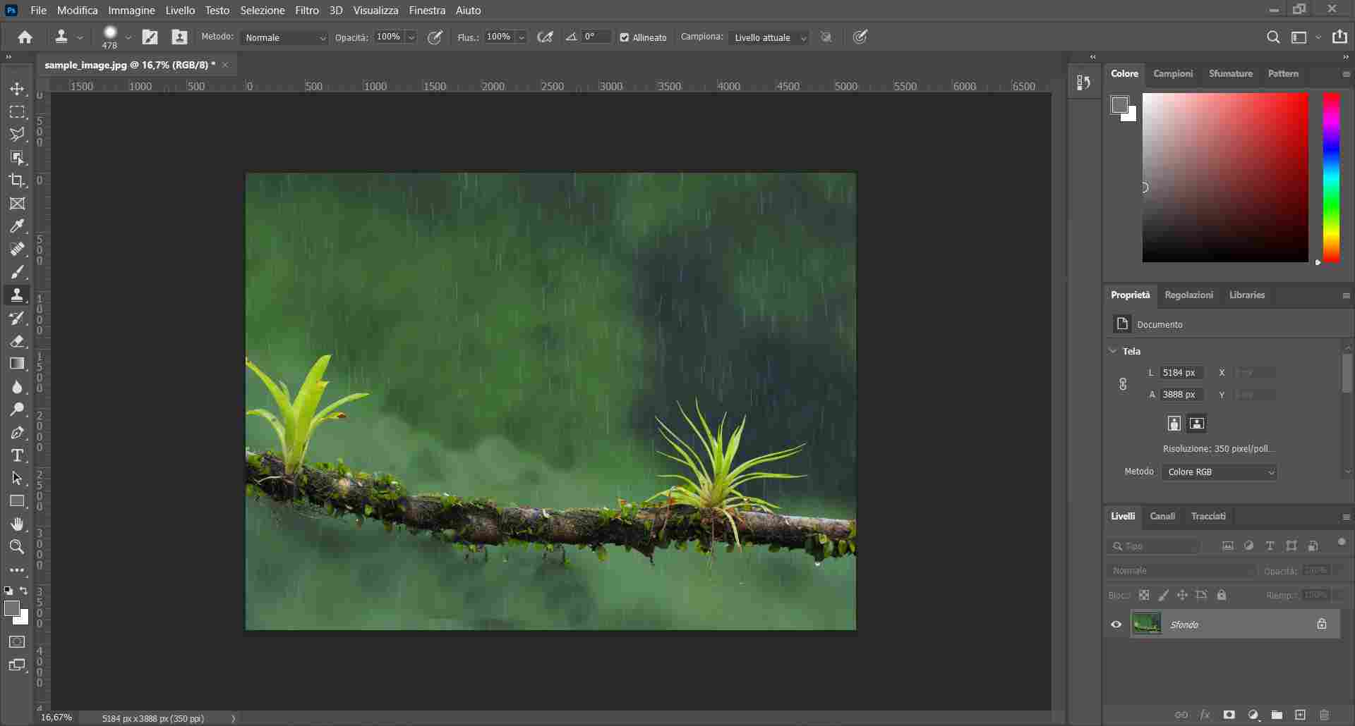
I’ve never worked with photoshop, if I had to work on some photo editing I’ve always used online programs like Canva or Ipiccy. I had the chance to install it, so what follows is a quick overlook on the basic usage of Photoshop:
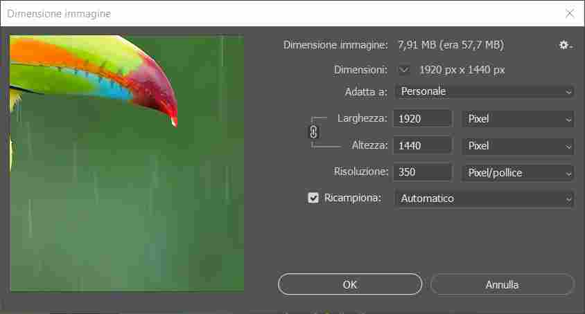
- Resize image
It is possible to change and reduce the dimension of an image. Clicking on image>resize, allows to do that and it is possible to maintain the initial proportions.
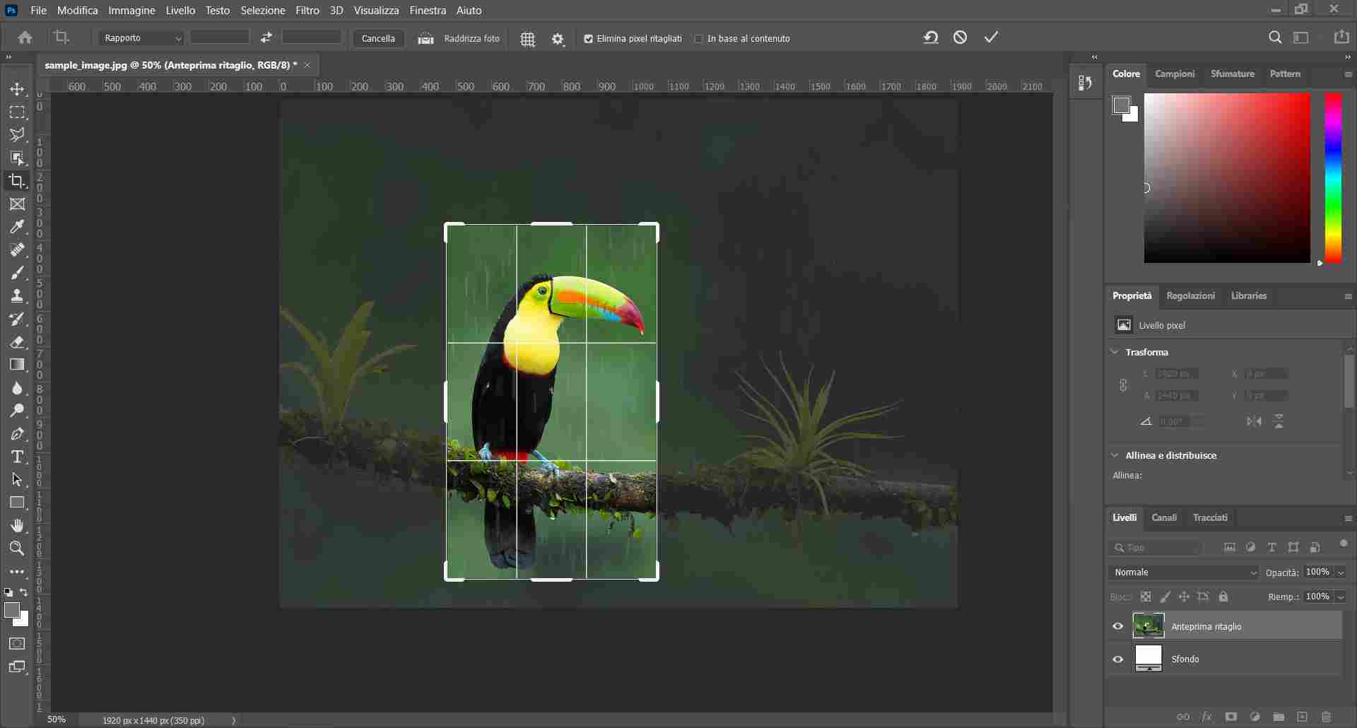
- Crop
Images can be cropped to the format or section we need. There is a tool on the left toolbar with the name crop on it. Once the area is selected, with image>crop it is possible to crop the image.
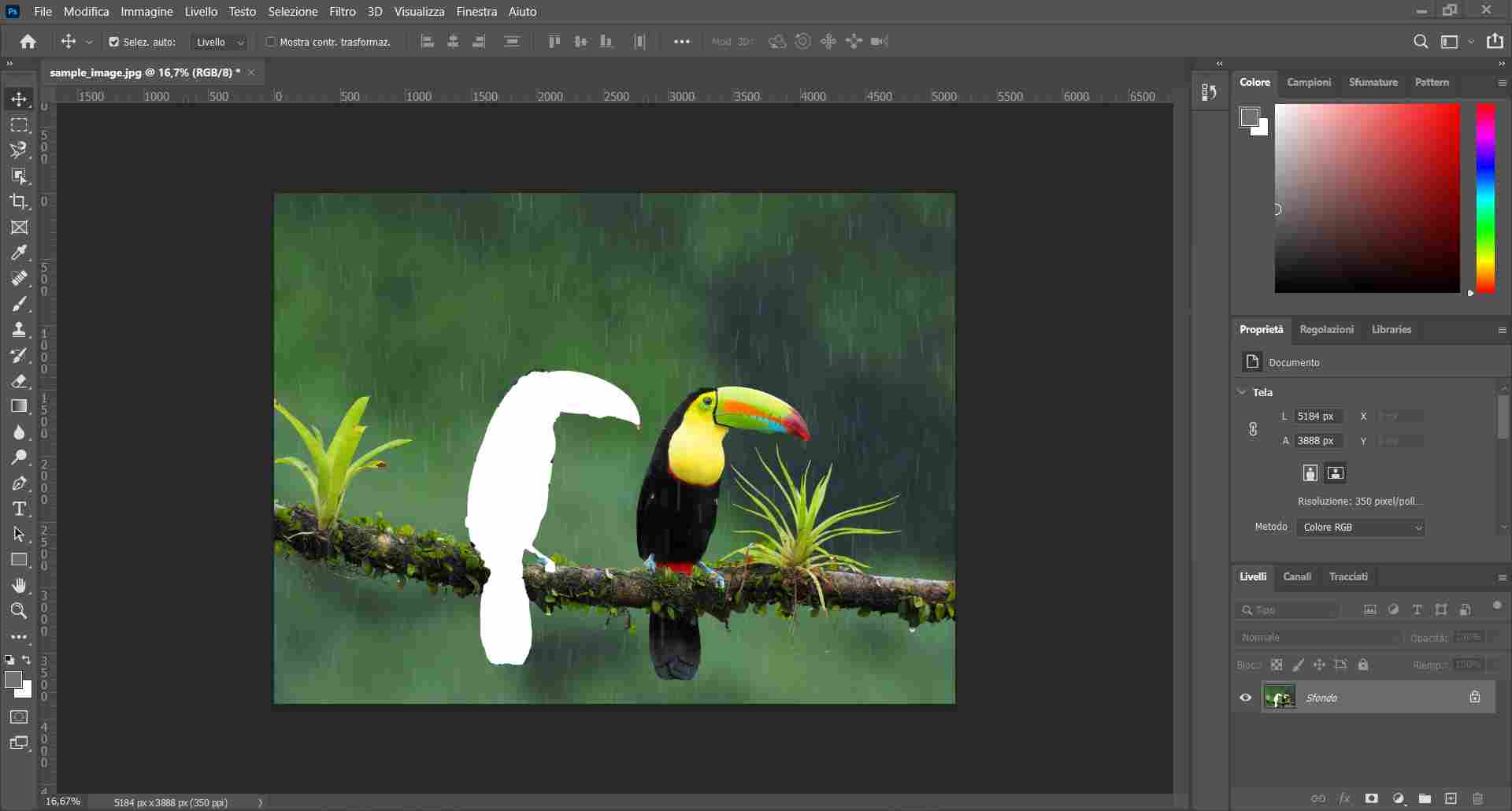
- Clone stamp
Images can be edited in order to set an area of pixels to look like a previously chosen area. It is possible to remove images cloning the background around them.
- Selection (lasso and marquee tools)
Sections of the image can be selected in order to be modified (changing color or applying other effects) or moved away. Once the selection has been done, the move tool (shortcut: v) does the job, dragging the selection around.
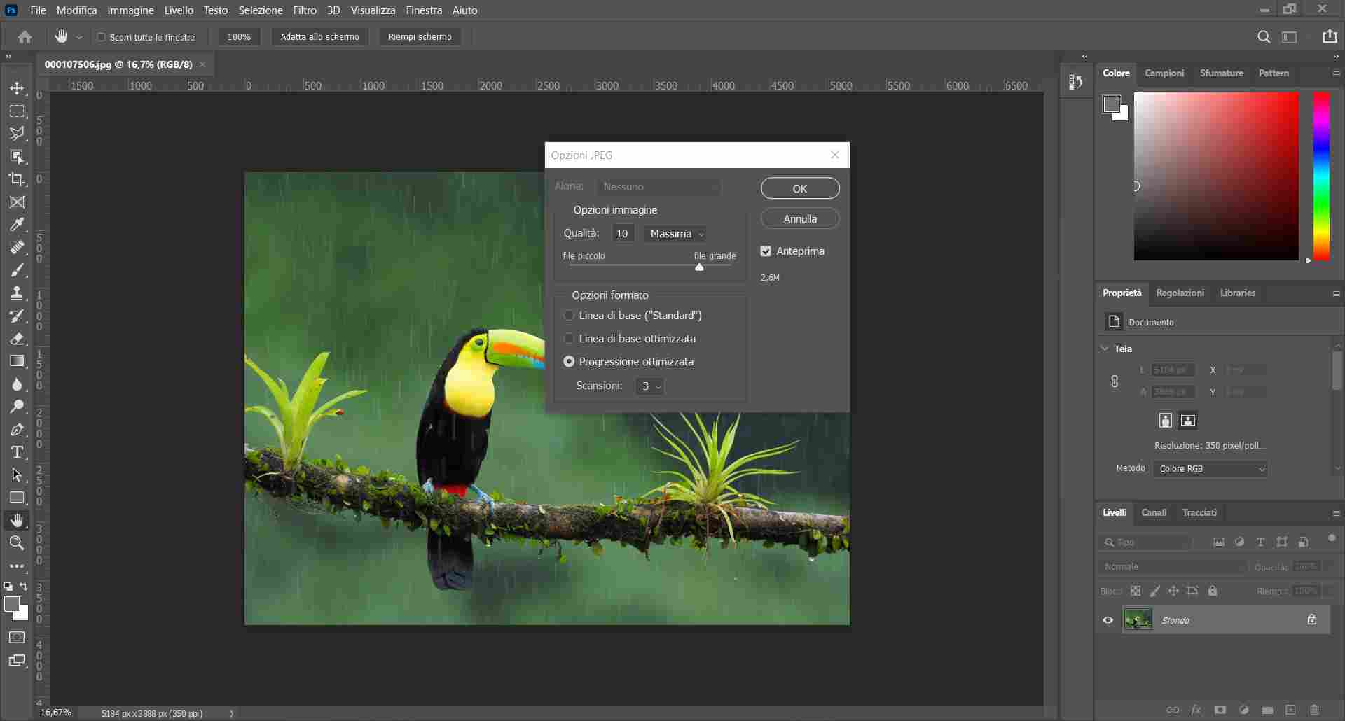
- Compress image
While saving (crtl + s), it is possible to choose the quality of the image that we want to save. There is a slider that goes from 0 to 12 and Photoshop tells immediately the file’s final size. In this case the image went from 5 MB to 79 KB. The quality is not printable but it is more than enough for web usage.
Useful links:
- Adobe Tools’ Guide
- Photoshop essentials’ overview
- Tools and Toolbar for beginners
- Basics of Photoshop
IRFAN VIEW
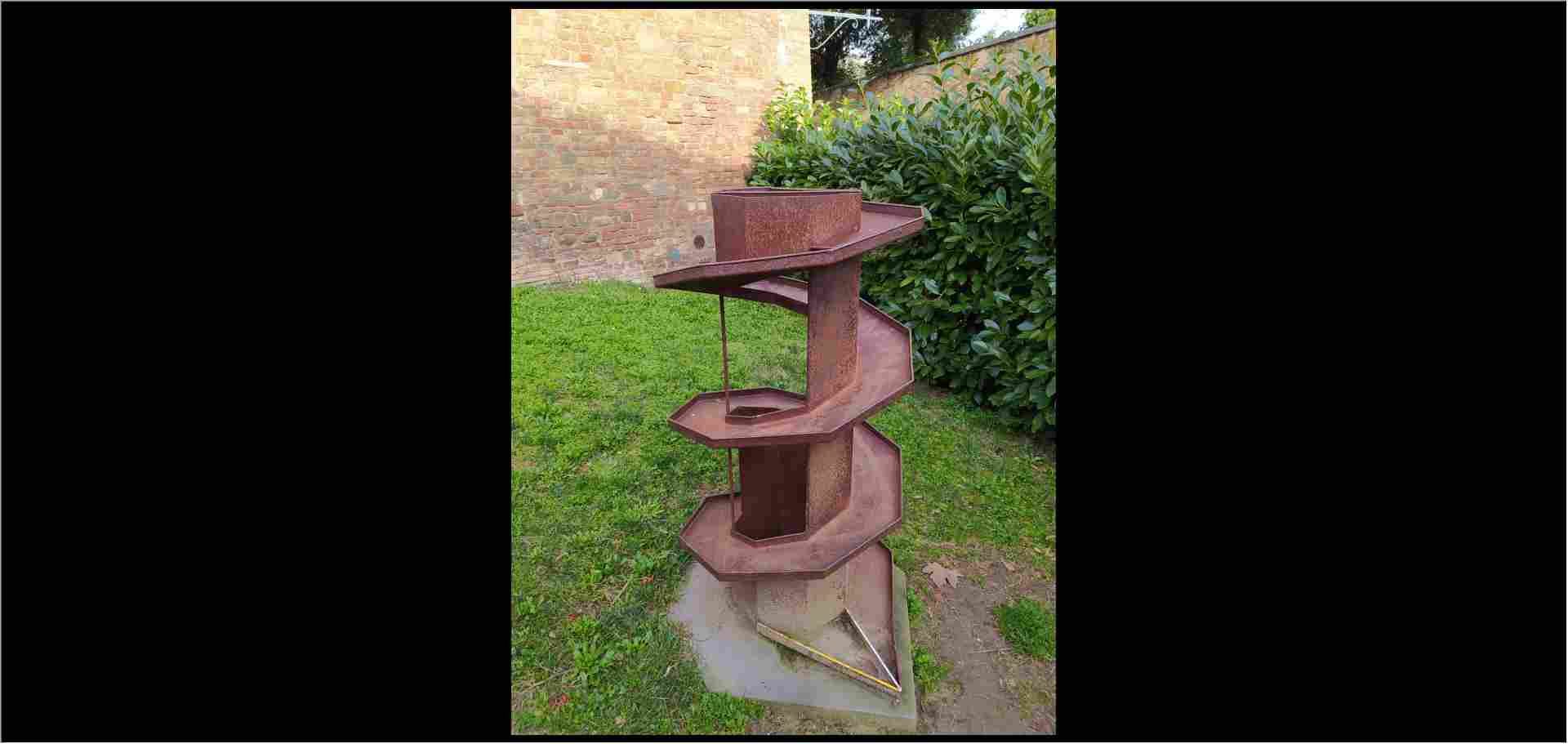
I usually use Irfan View, which is quite light and suitable even for older machines, for cropping and resizing images. I heard about it for the first time during my traineeship at the communication agency I mentioned in my about page. It is available only for 32 bit and 64 bit windows OS. Cupertino won’t like that… I did not use any project image for Photoshop but I will use the same image I used with Inkscape. Here are the basic tools, very useful for pushing lighter images on our repositories or for faster loading webpages:
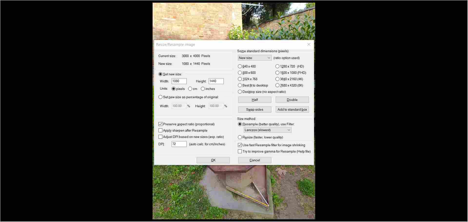
- Resize (ctrl + r)
It is possible to reduce the image’s size and make it closer to the final resolution.
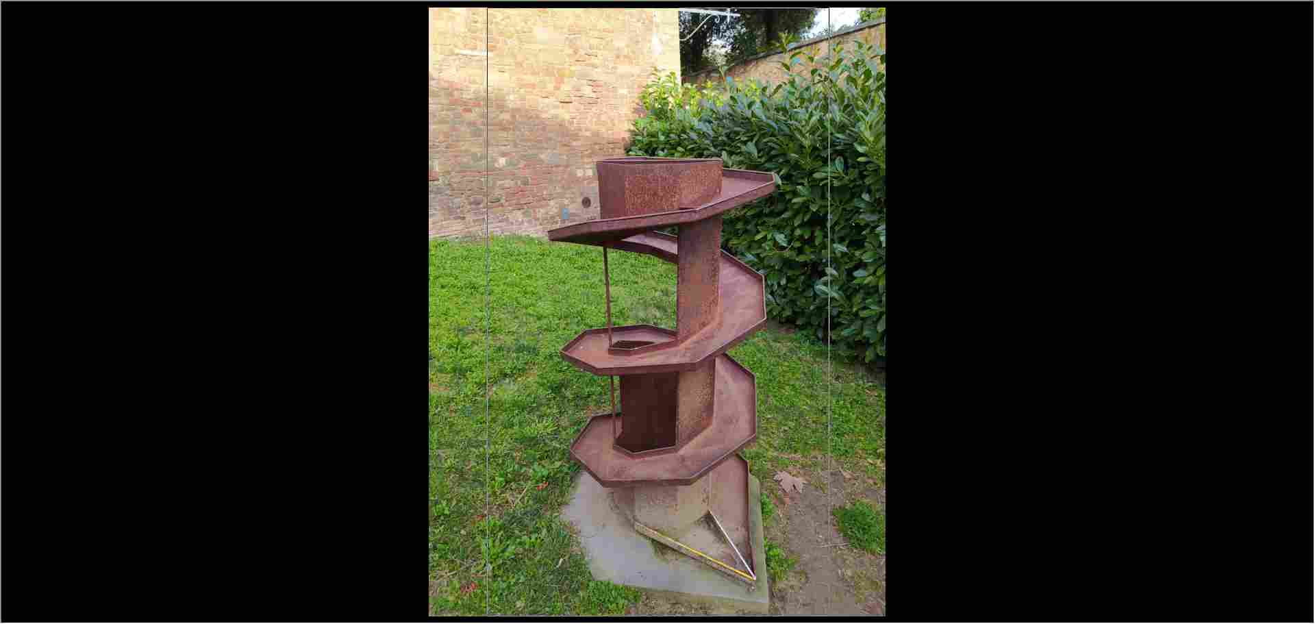
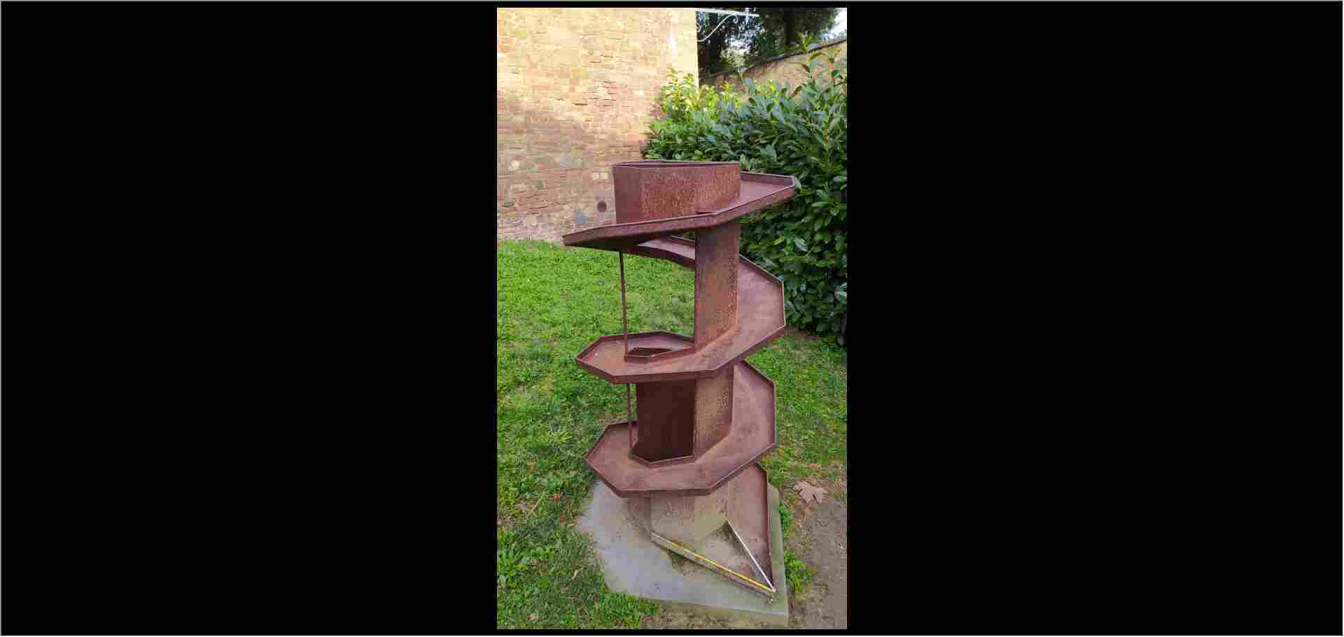
- Custom selection (shift + c) + Crop (ctrl + y)
It is possible to draw a section over the image and to crop it. Usually this is useful for obtaining proper image size for websites and social network images (which have fixed/recommended sizes).
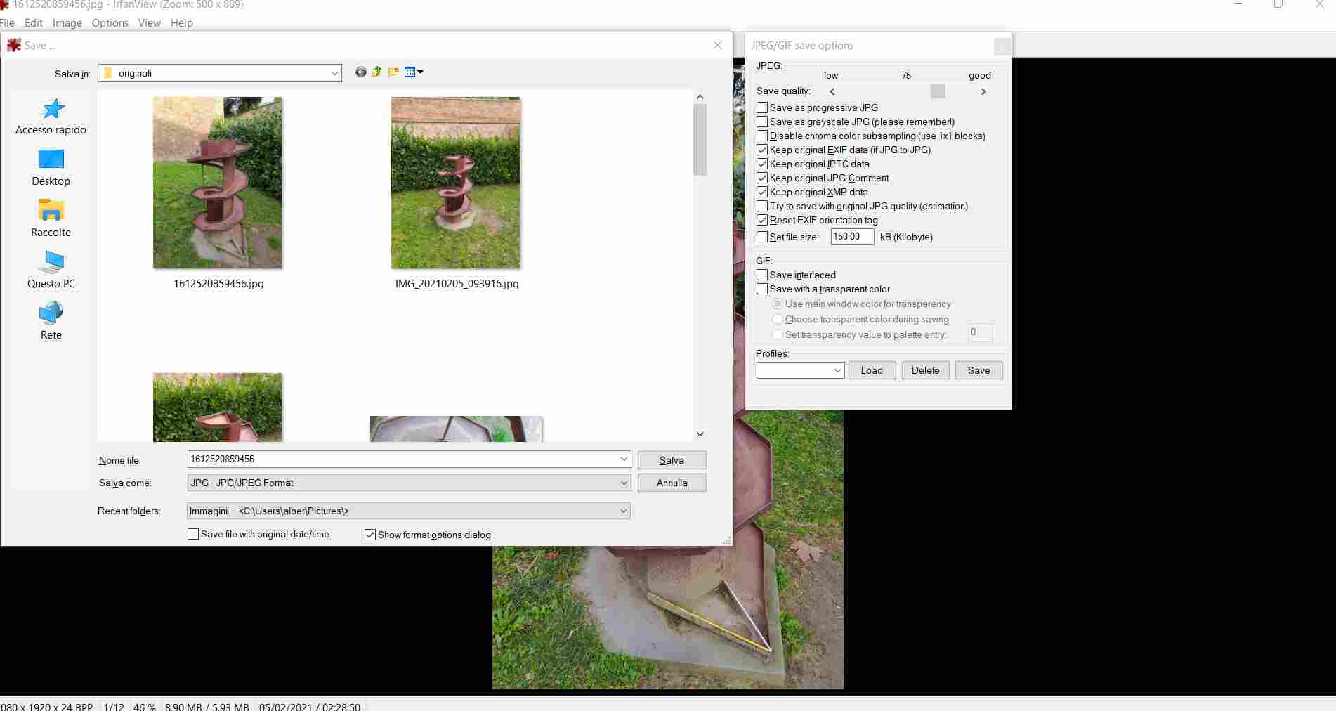
- Save and compress (ctrl + s)
Once the editing is over, it is possible to save and to decide the output file and how much compression we want for our picture. We can decide like Photoshop through a slider from 0 to 10 or directly choosing the image weight that you want. The software will do the rest.
Useful links
3D softwares
RHINOCEROS 7
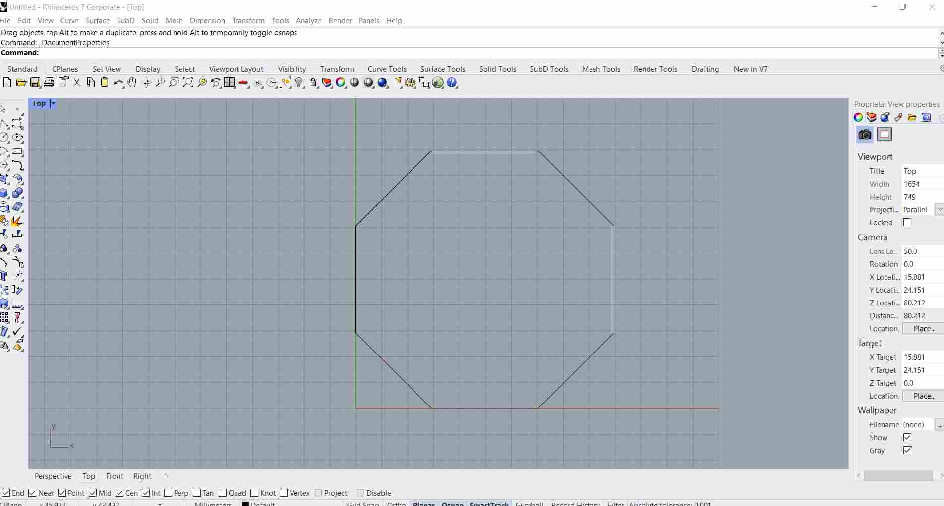
Once the software has been installed, I started looking for some video tutorials. The first I looked at is this. All the commands are placed on the left toolbar. The initial setup in Rhino shows 4 windows to users (4 perspectives). It is possible to change them right-clicking on their name up on the left corner. It is also possible to select and focus on one specific perspective clicking twice on the same button up on the left corner. Lines can be drawn freely in all directions but if I press shift Rhino allows me to draw only 90° lines. There is a command line at the top of the window. For example, if I select the polyline tool, I can write 0 on the command line in order to make the starting point of the polyline tool at zero. Here I started doing an octagon into a bigger one.
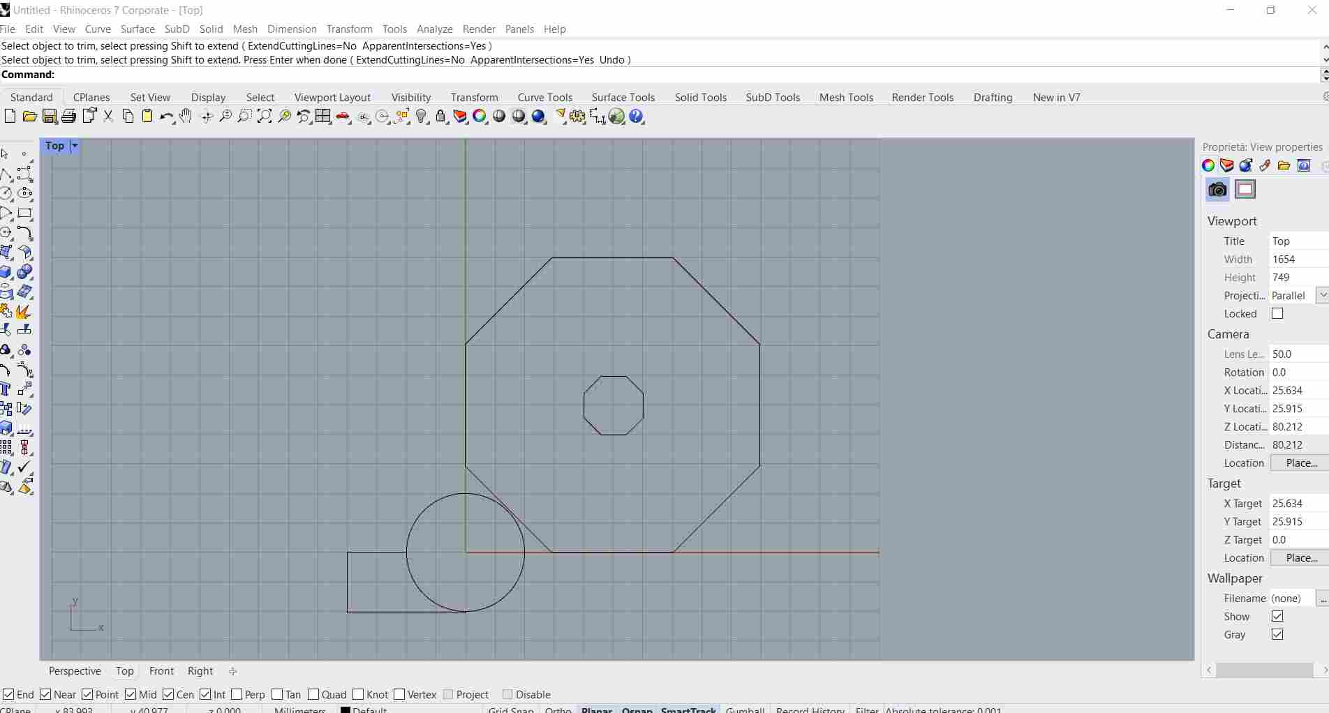
Then I drew a circle and rectangle, using them as training dummies. If two or more shapes cross each other, it is possible to remove the inner crossed lines and keep only the external ones through the trim command.
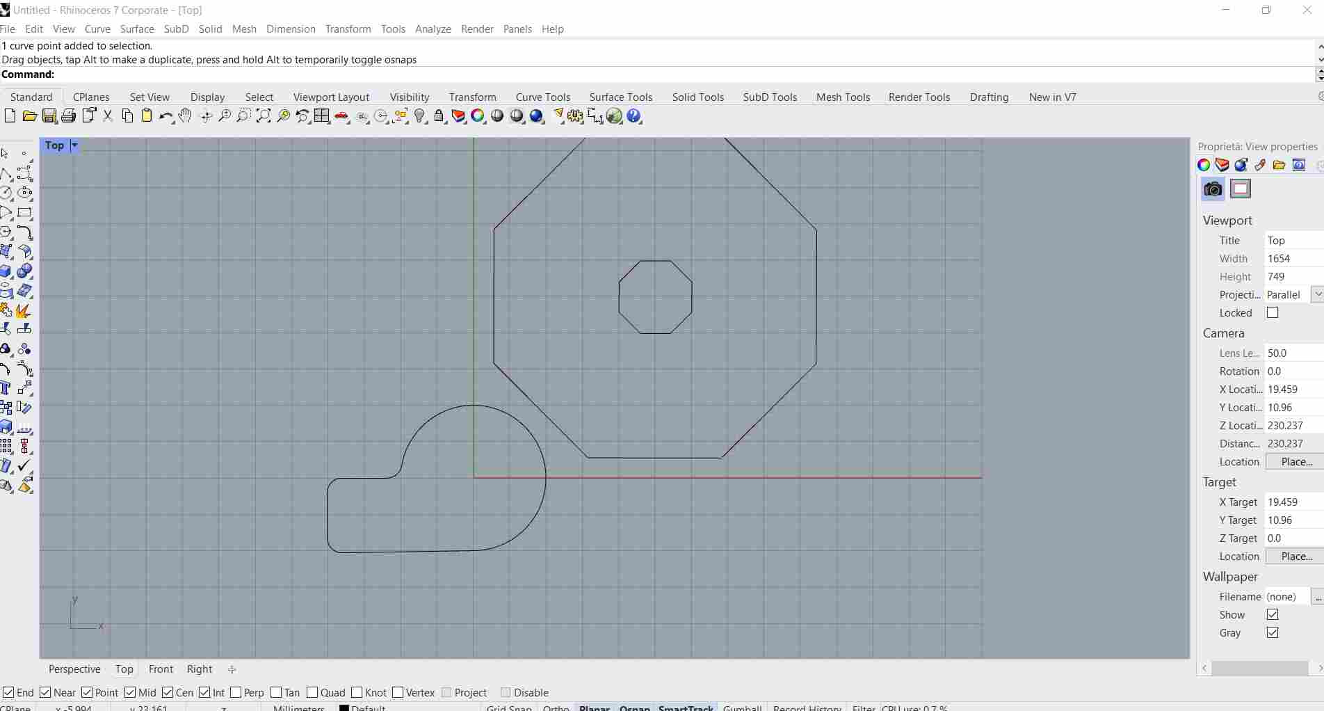
It is possible to round the corners using the fillet curve command.
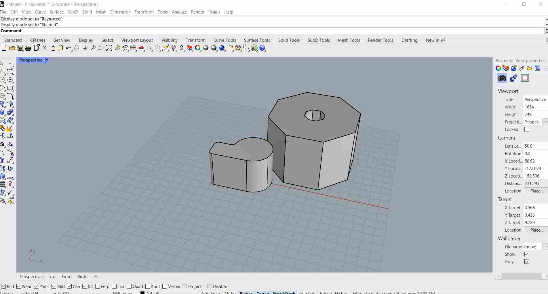
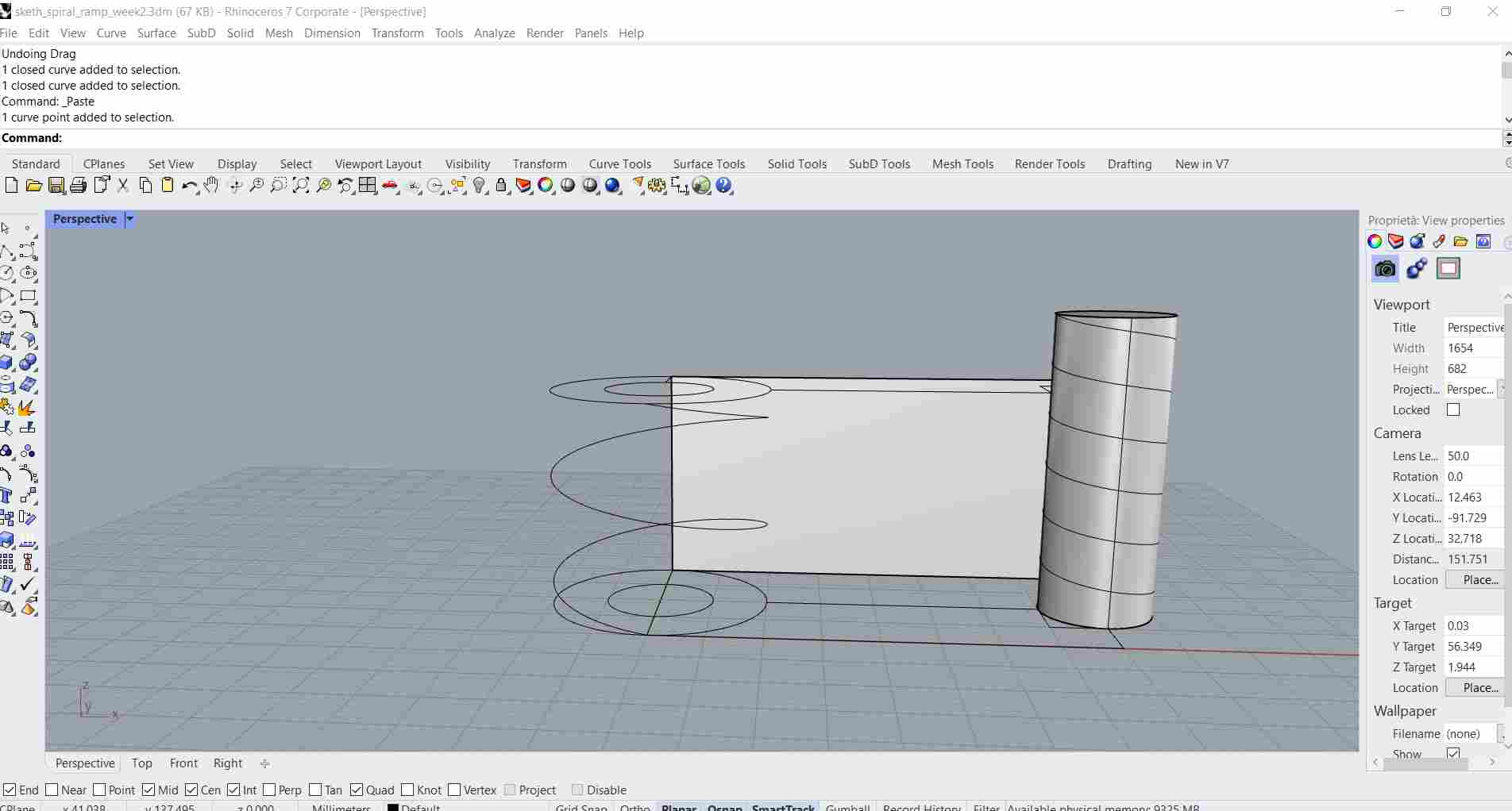
Clicking with the right mouse button recalls the last command used (if there are not already opened commands). Once the 2D shape is done, I have to select the extrude command in order to create a 3D object. It is possible to decide a few basic things like the direction, the length and the absence or presence of the bottom and top surfaces. Once the shape has been extruded, it is possible to see different visualizations (wireframe, shape and render are the most common ones).
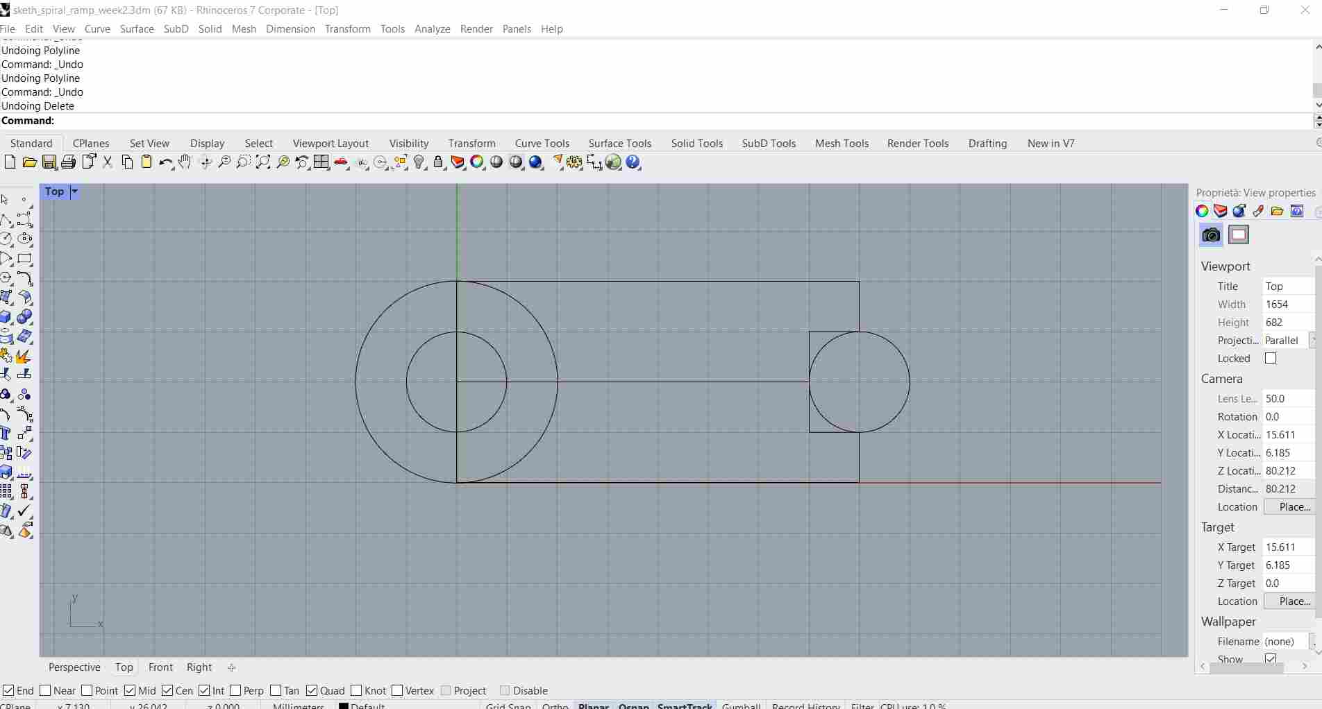
Then I started thinking that maybe a round helix structure for the ramps could do the job. So I started again from an empty project and drew a structure from the top view.
I created a second floor, which had to be linked with the bottom level through two helixes: one for going down and another one for going back up.
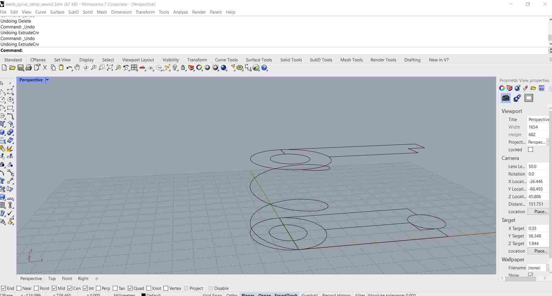
It took me a while to reach this point in the modeling of the final project, so I decided to try another software and see if I could find my way with 3D modeling.
FUSION 360
Tutorial
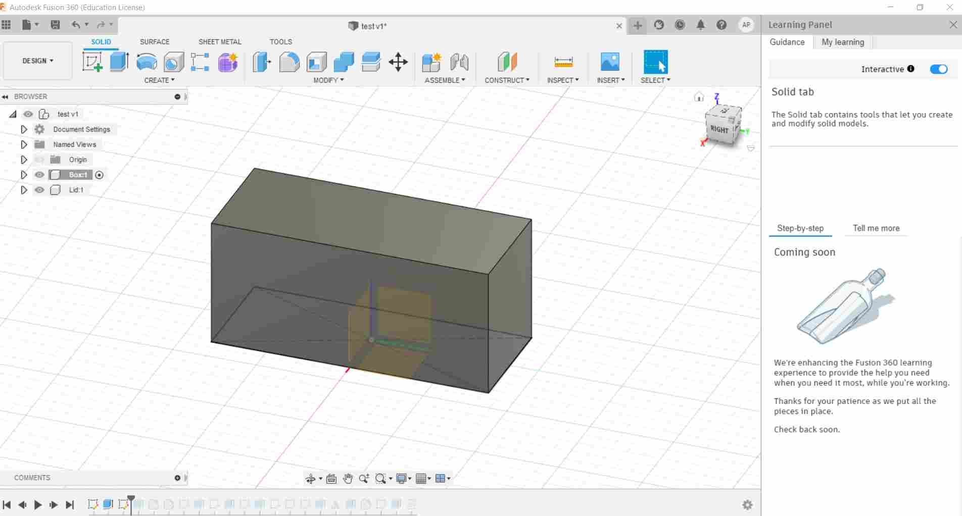
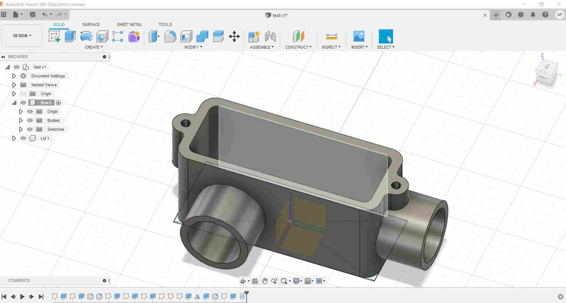
Since I wanted to start from the basics, I found a very useful tutorial made by Lars Christensen on youtube that started from zero and allowed me to find out the basic tools. The tutorial started from the creation of a new component, known as “box”. Then I created a sketch on the top plan, I made a rectangular shape (63mmx34mm). Through the shortcut Q key I’ve been able to pull the sketch and extrude a 3D shape.
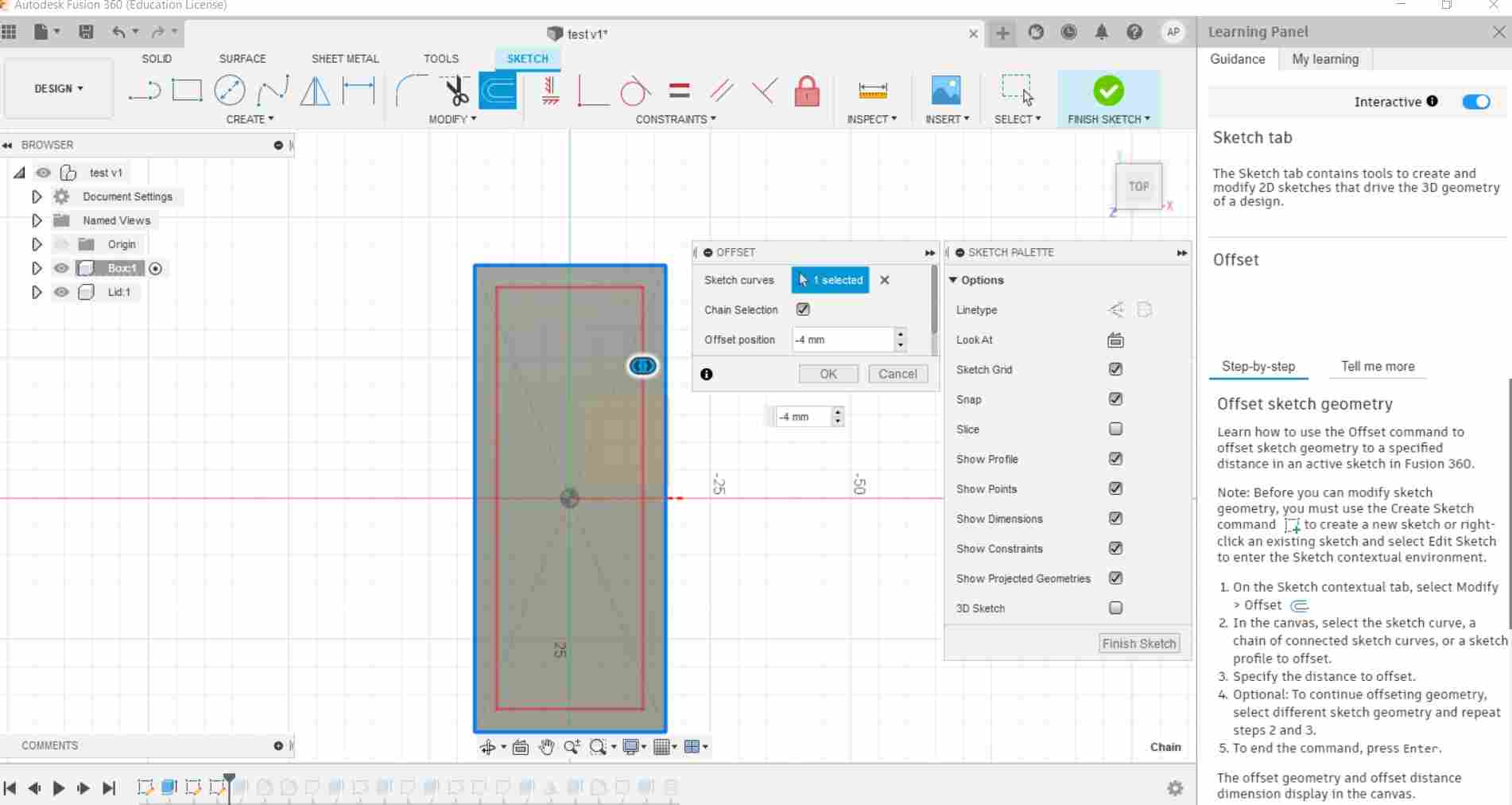
Then I right-clicked on the top surface of the box and created a new sketch on it. Since I wanted to make a regular distance from all the sides, instead of making a rectangle from the center I made a -4mm offset and confirmed the sketch.
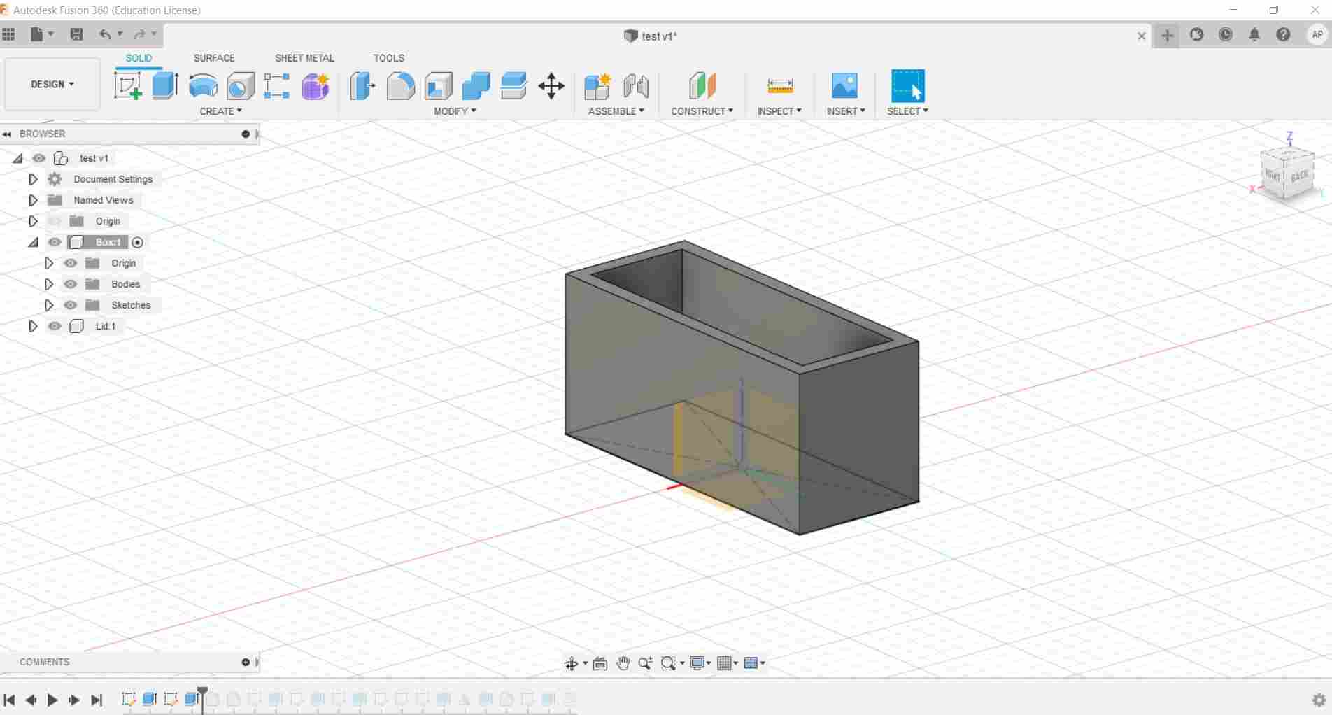
After that, I press the Q key and I started the extrusion process. This time I wanted to be a negative distance in order to dig into the box. Instead of using the “distance” extent type, I used the “to face” type and selected the bottom surface. Doing this, I’ve been able to set the same 4mm distance from the bottom level.

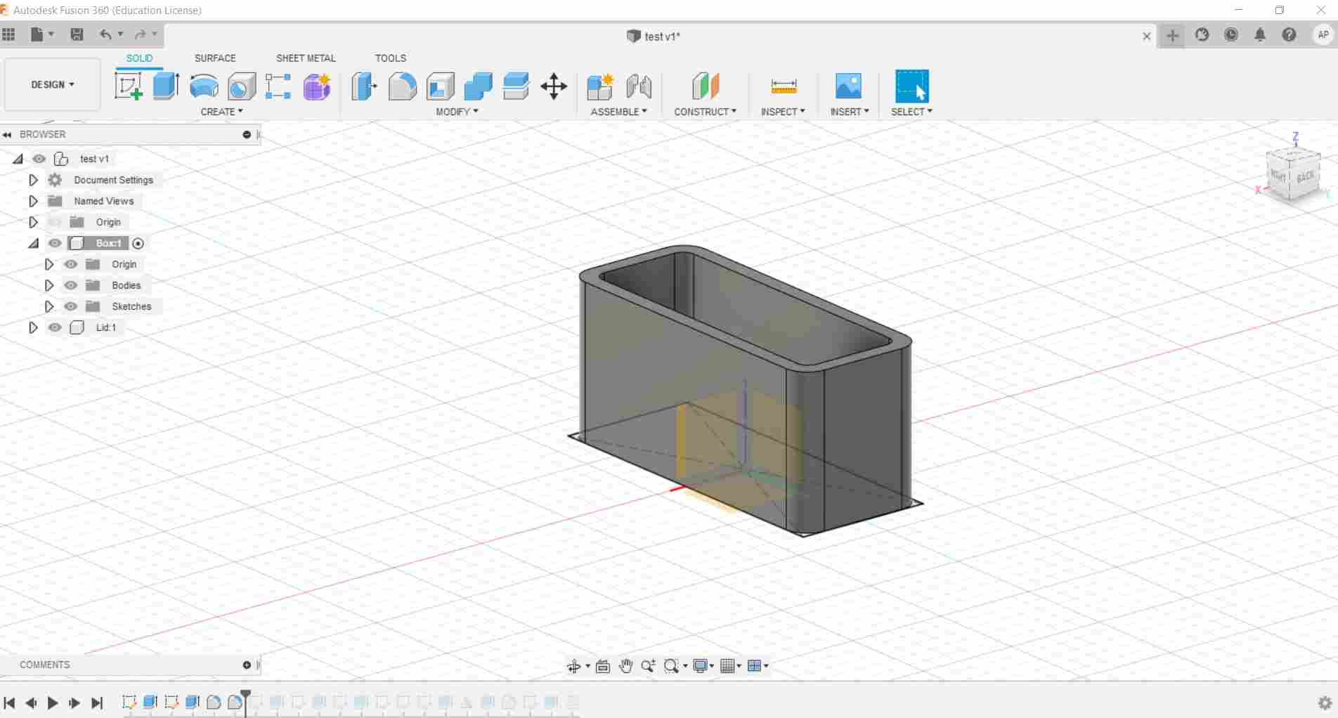
Once the inner space has been created, I used the fillet tool and I rounded the corners of both the inside and the outside of the box.
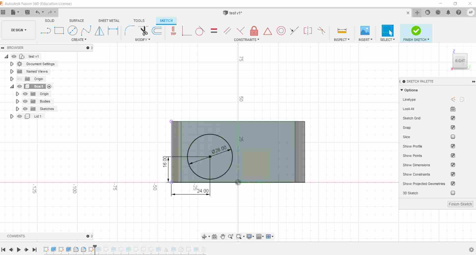
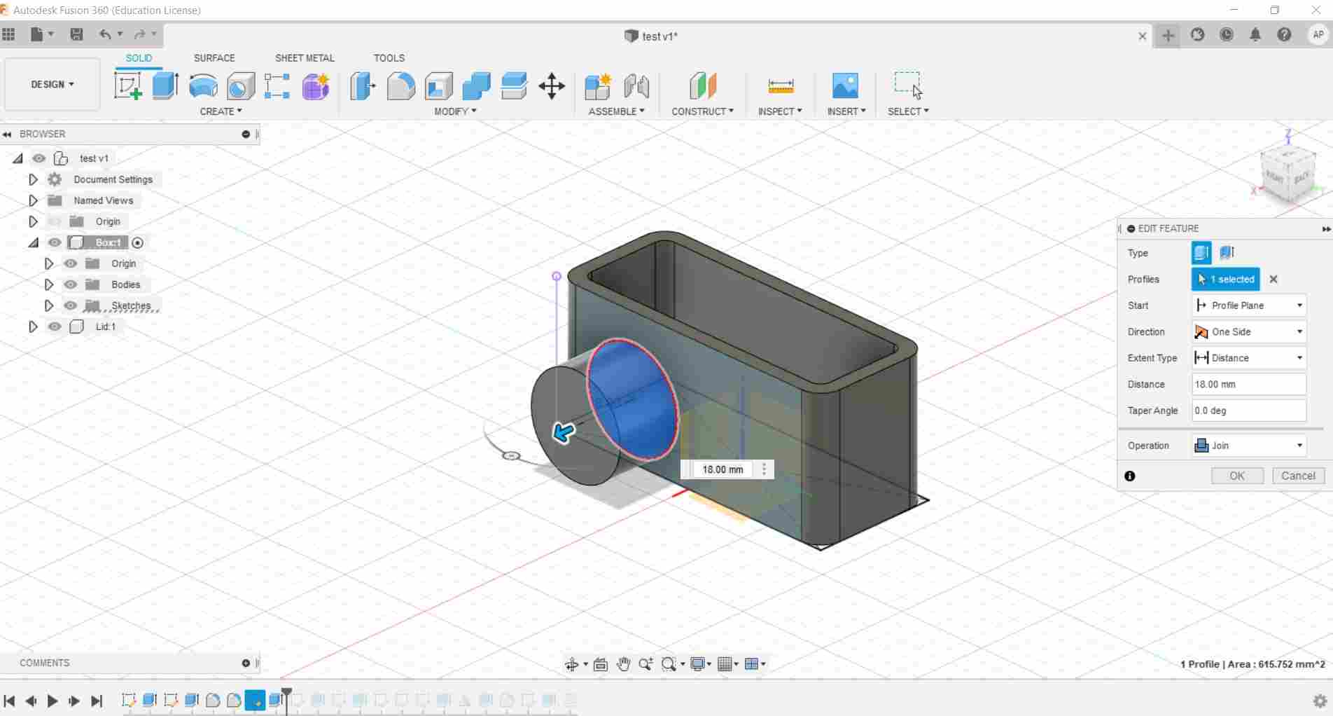
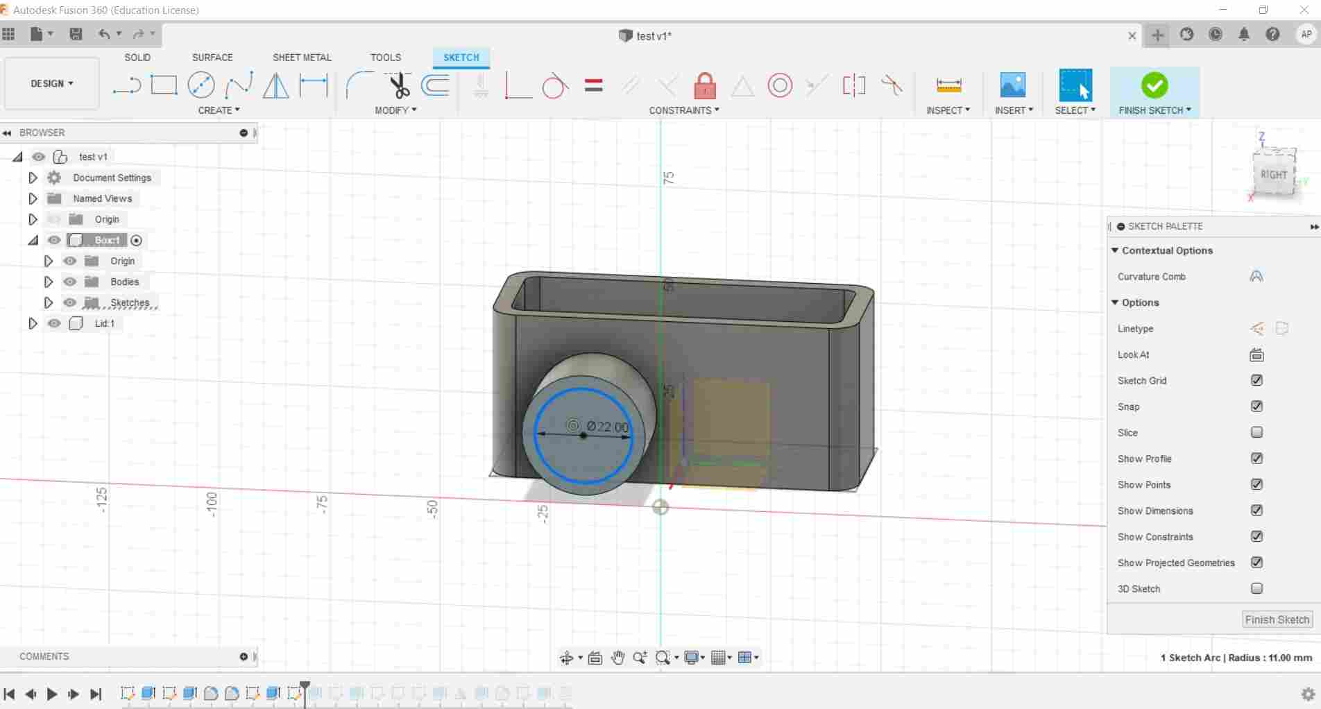
Moving on, I right clicked on the wide side surface and made a new sketch on it. I made a circle and put the specific dimensions pushing the D key, then selecting the center of the circle and the surfaces of the plan. Then the circle’s sketch has been confirmed and extruded.
After that, I made a hole on the circle. I drew a sketch on the surface and set the extrusion settings so that I could made a inner shape that reaches the inner surface of the box. Doing that, the hole ended precisely on the surface of the box.
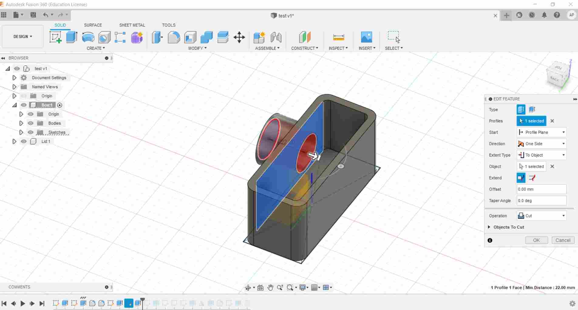
I did the same on the narrow side of the box.
Then I moved on the top surface, I made a small circle on one side and mirrored it on the other side.
Once both circles were extruded, I used the fillet tool and made a inner hole on both.
The inner hole have been made in order to create a thread section inside.
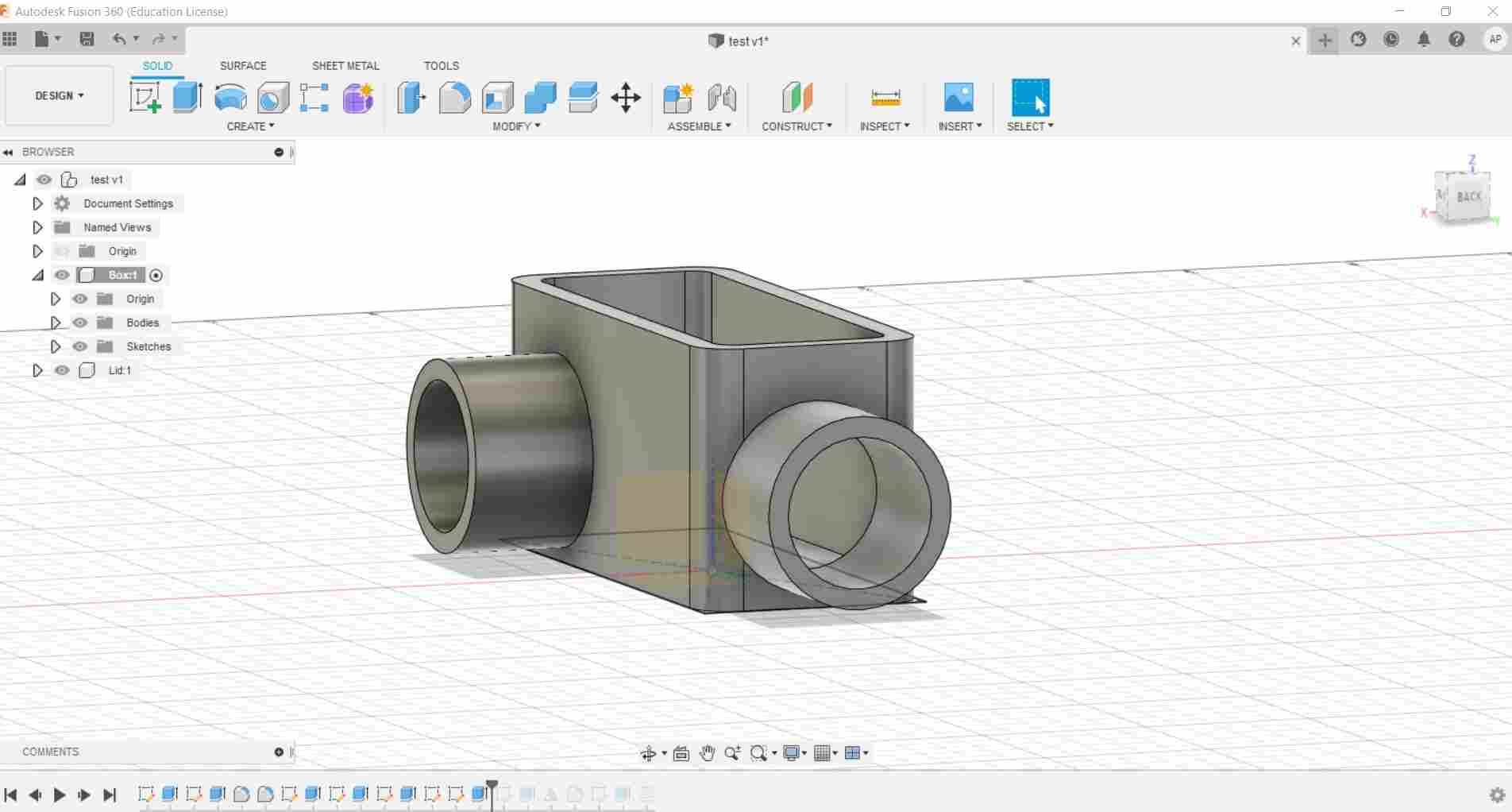
I had to move the extrusion process of the narrow side to the end of the timeline since I wanted to cut the exceeding thread hole.
This is the final result of the box.
Final Project 3D modeling
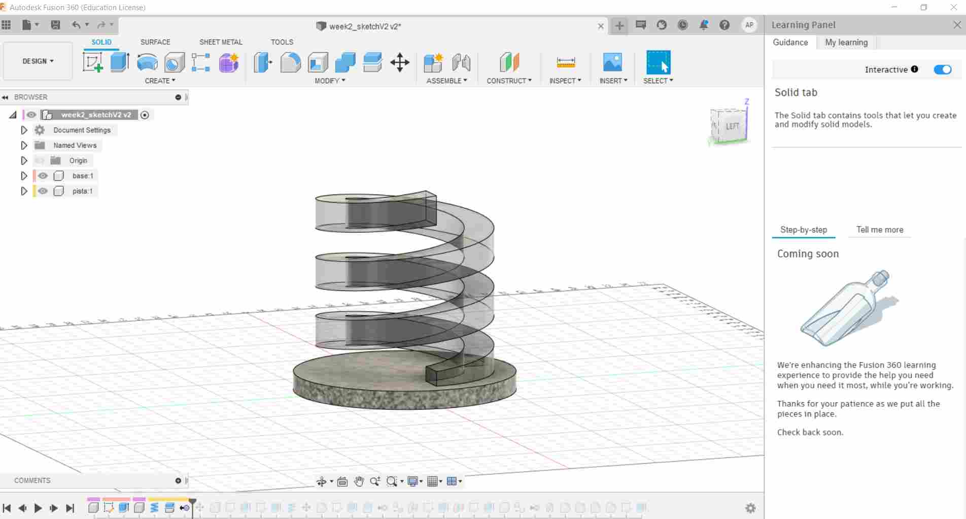
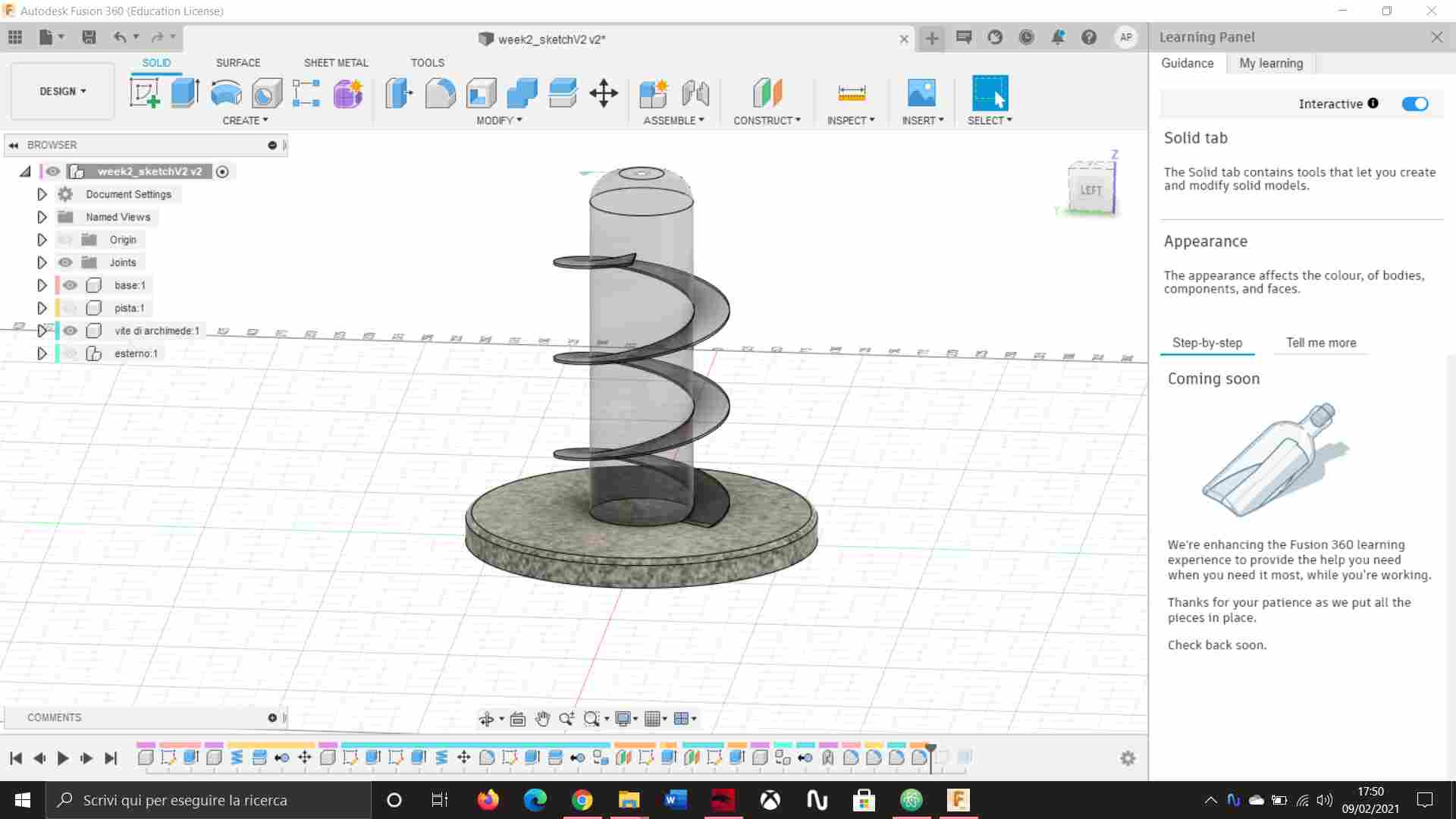
I started modeling my final project with Fusion 360 by creating a circular base. On top of that I made a new component, making a coil and using it as the marble track. At the end of the track there is a small wall that makes the marbles reach the inner pat of the model.
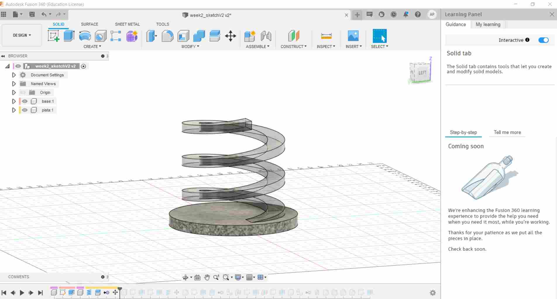
Then I worked on the top view of the base, making another smaller coil starting from the center of the base. This second coil is going to be modeled for the real final project as an Archimede’s screw, in order to bring the balls back to the top. I had to make both coils thinner modifying the z axis once the top face was selected.
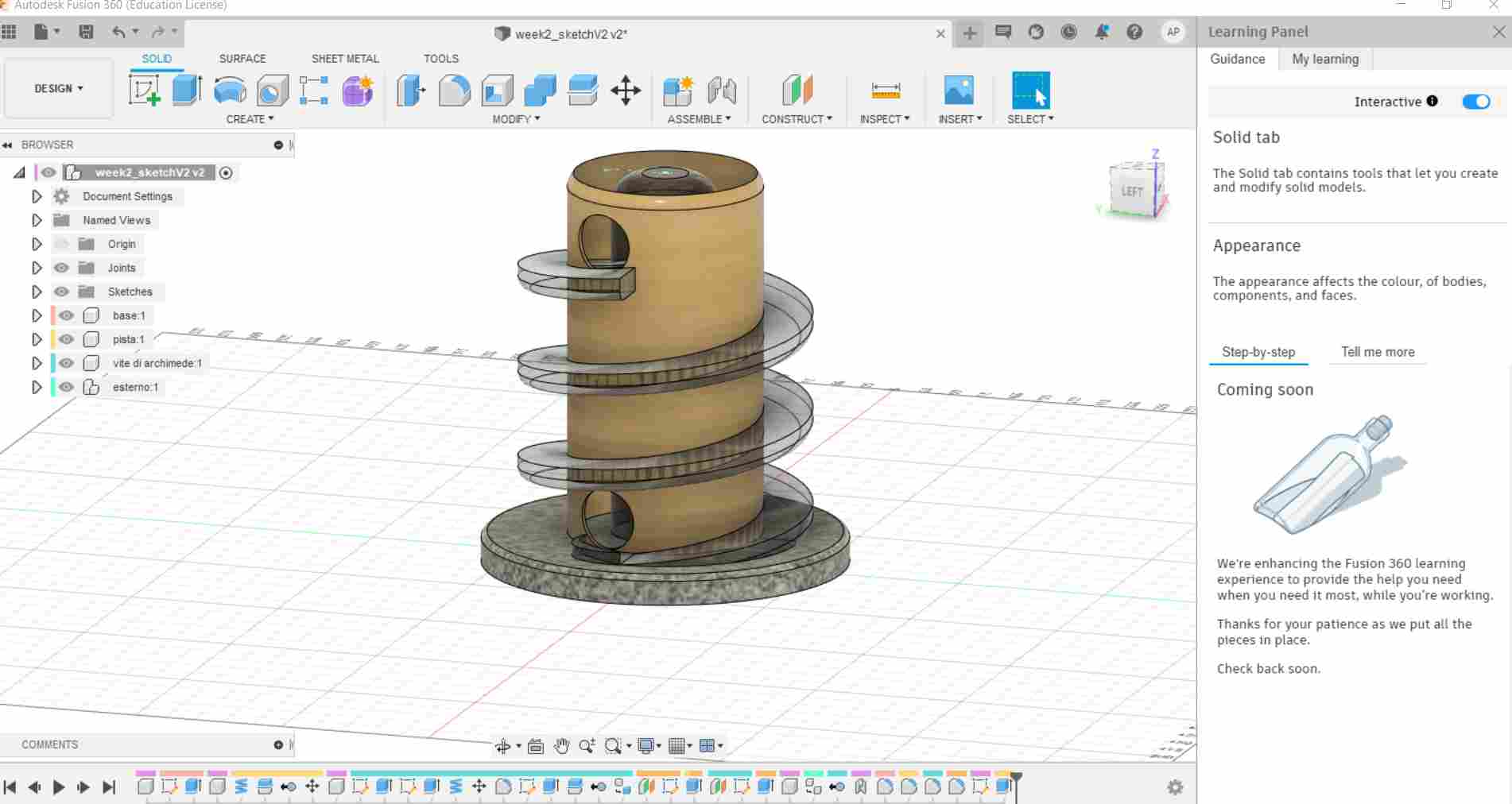
Once both coils were made, I decided to create a cylindrical structure that separates the coils and works as a wall for the marbles. After that, I made a perpendicular offset from the base, creating two holes in the structure. This holes have been made in order to allow the marbles to reach the start of the inner coil and go back to the top.
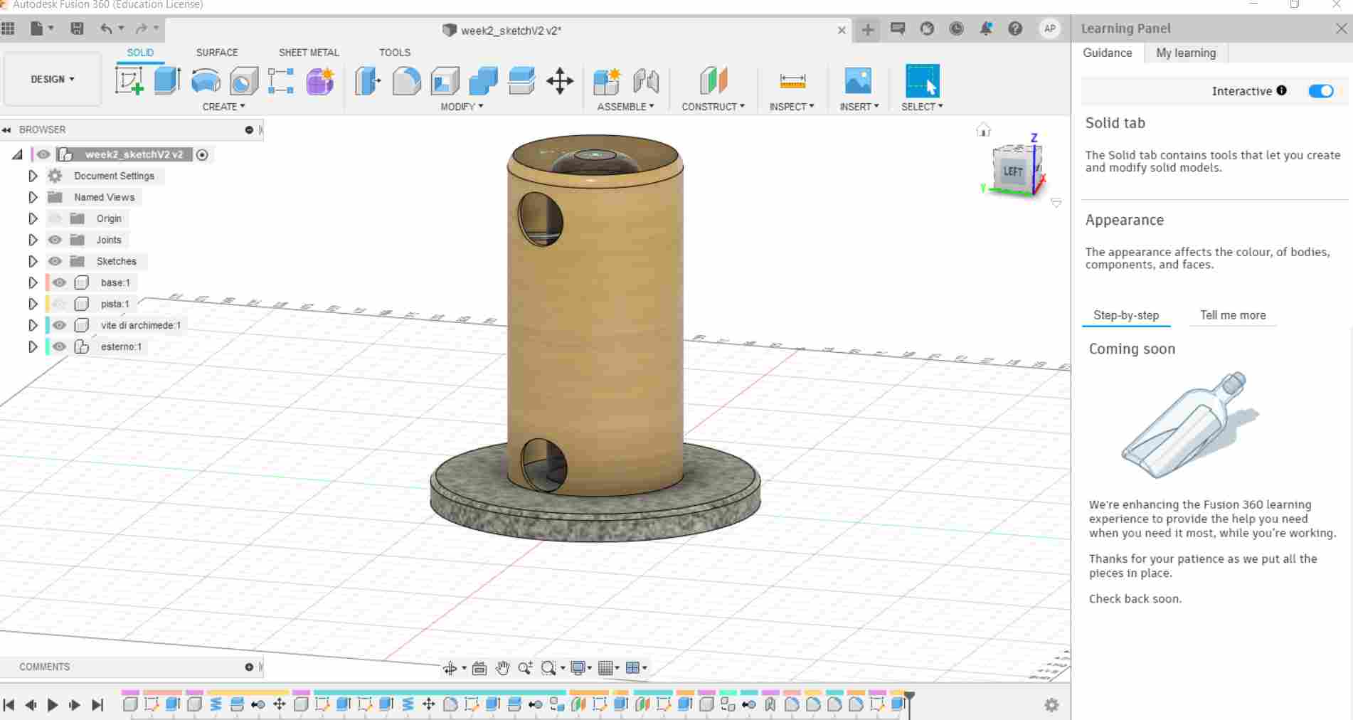
I assembled the internal coil with the structure, in order to make rotate the screw. This is the model with all its components put together.
The file of my 3D model for this week can be downloaded clicking here.