6. Electronics Design
This is the assessment for this module:
Group assignment
- Use the test equipment in your lab to observe the operation of a micro-controller circuit board
Individual assignment
- Redraw an echo hello-world board
- Add (at least) a button and LED (with current-limiting resistor)
- Check the design rules, make it, and test it
- Extra credit: simulate its operation
Group assignment - Test the lab’s equipment
You can find the group assignment documentation here.
Individual assignment - Redrawing the board
Eagle
Schematic
I’ve chosen the ATtiny45 from the list. Once all the materials have been double-checked, I downloaded the Fab library here and opened a new Eagle project.
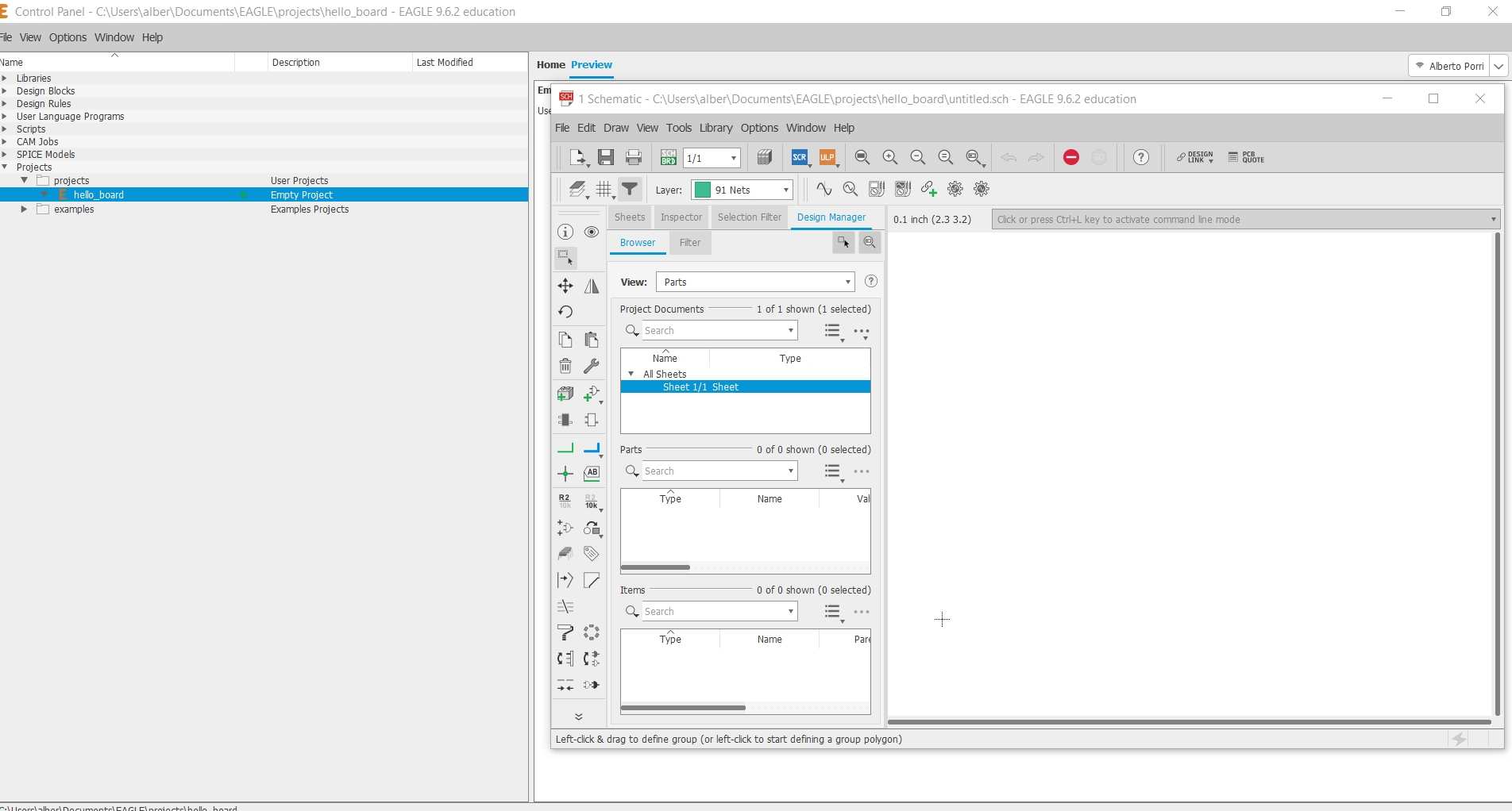
The first thing to do into a new schematic is to add all the components. I could find most of them on the Fab Library previously installed, but the 6x1 connector, the VCC and GND parts have been taken from the basic Eagle library.
Datasheet
Most of the components were previously determined, but I had to find the proper resistor for the new LED. I had to find the LED’s data sheet, so first I found the green LED on the inventory. Once I found the LED code, I could download the datasheet from Digi-key.
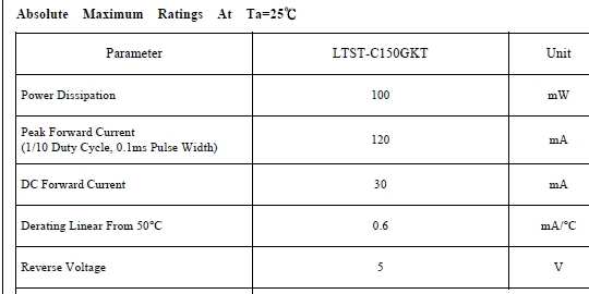
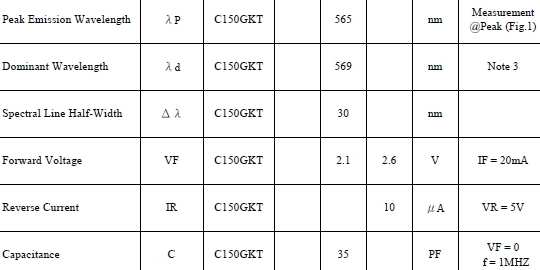
The LED seems to require 30 mA for being turned on and a 2.1 voltage. Ohm’s law allows me to obtain the minimum resistor value required for this LED to work. A 100Ω resistor could do the job, but I want to be sure and use a 500Ω resistor.
I connected all the parts with each other, trying to avoid messy traces using labels. This is the schematic I made:
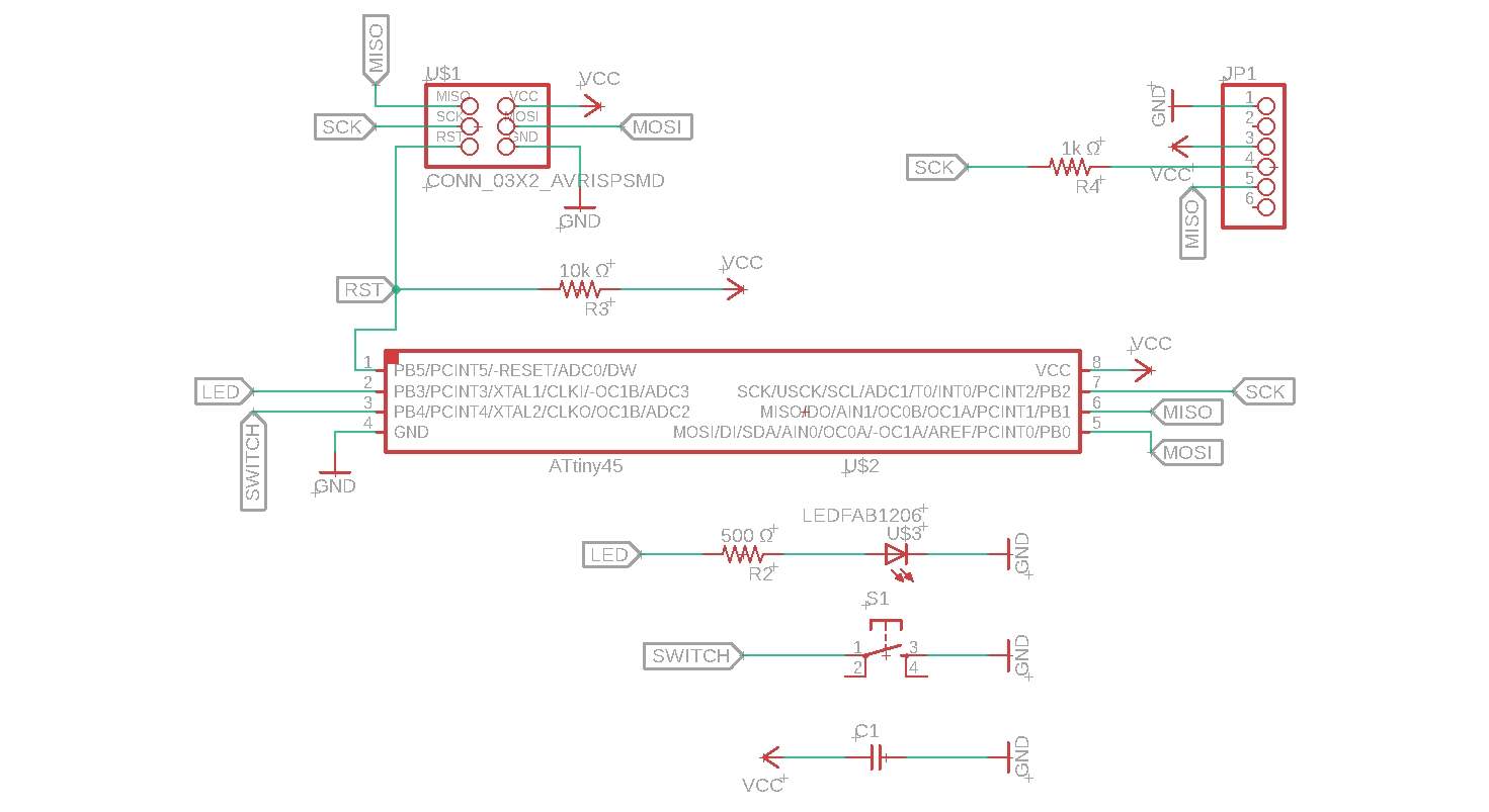
You can download it here
Board
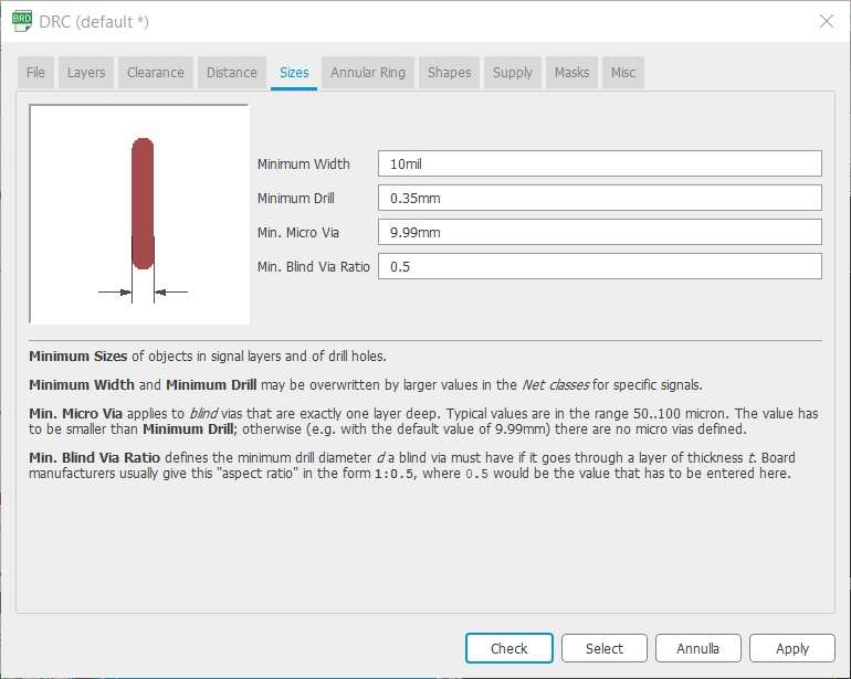
Once the schematic looked good, I moved on and started aligning all the parts into the board. I set a 17mil clearance and a 10mil minimum width.
![]()
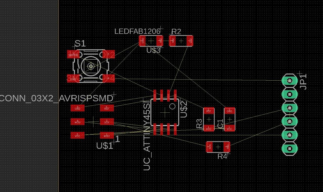
The initial guiding wires between all the parts seemed a little confusing, since they were crossing each other a thousand times.
Once all the parts have been connected, I ran the DRC function that showed me no errors but 2 wire stub warnings.
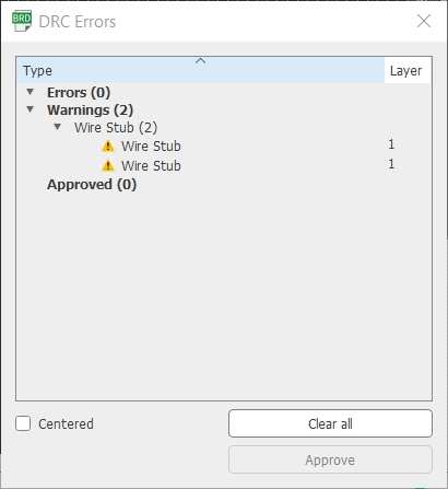
I had to delete the traces were Eagle showed me the wire stub, probably I left some wire below the pads. Once the new traces have been made, I ran DRC again and this time no errors or warnings appeared.

This is the final board, ready to be exported as a png into Photoshop.
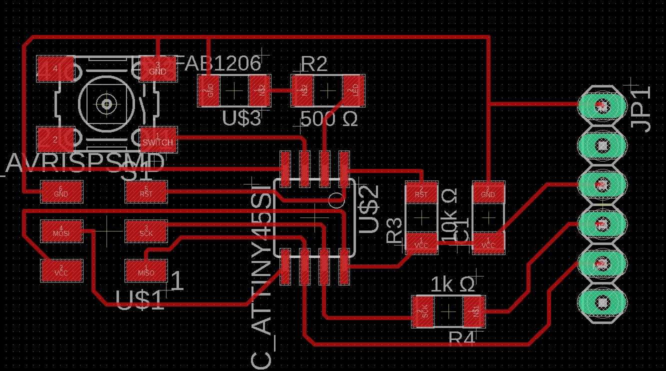
You can download it here
In order to obtain a clean png for the milling process. I had to export the board with 4 layers only:
- top
- pads
- vias
- dimension
This is the png I obtained:
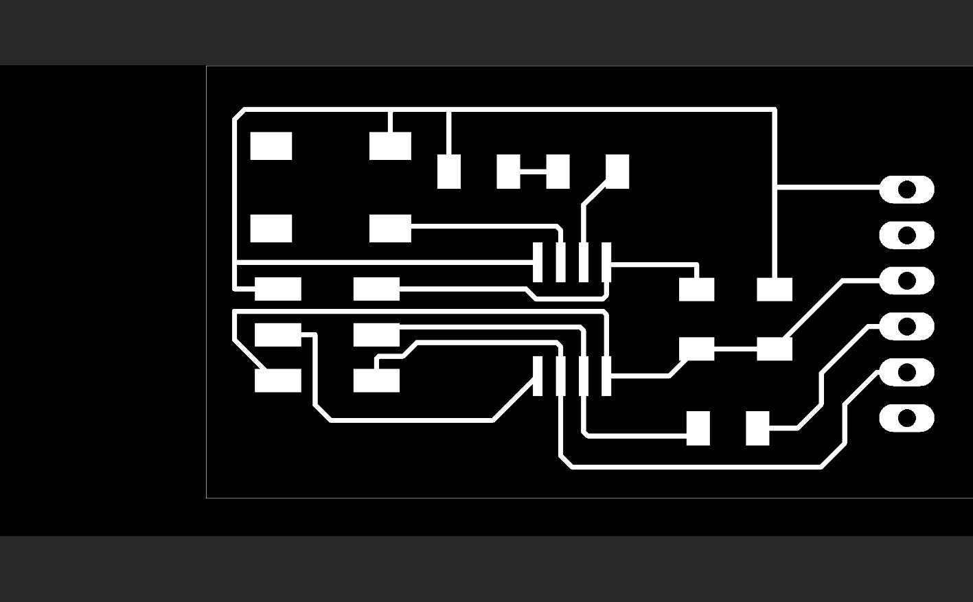
Photoshop
The png file obtained from Eagle is far from the final form the milling machine needs.
From the original image I had to obtain three different images:
The image that tells the machine how to mill the board in order to obtain the traces:
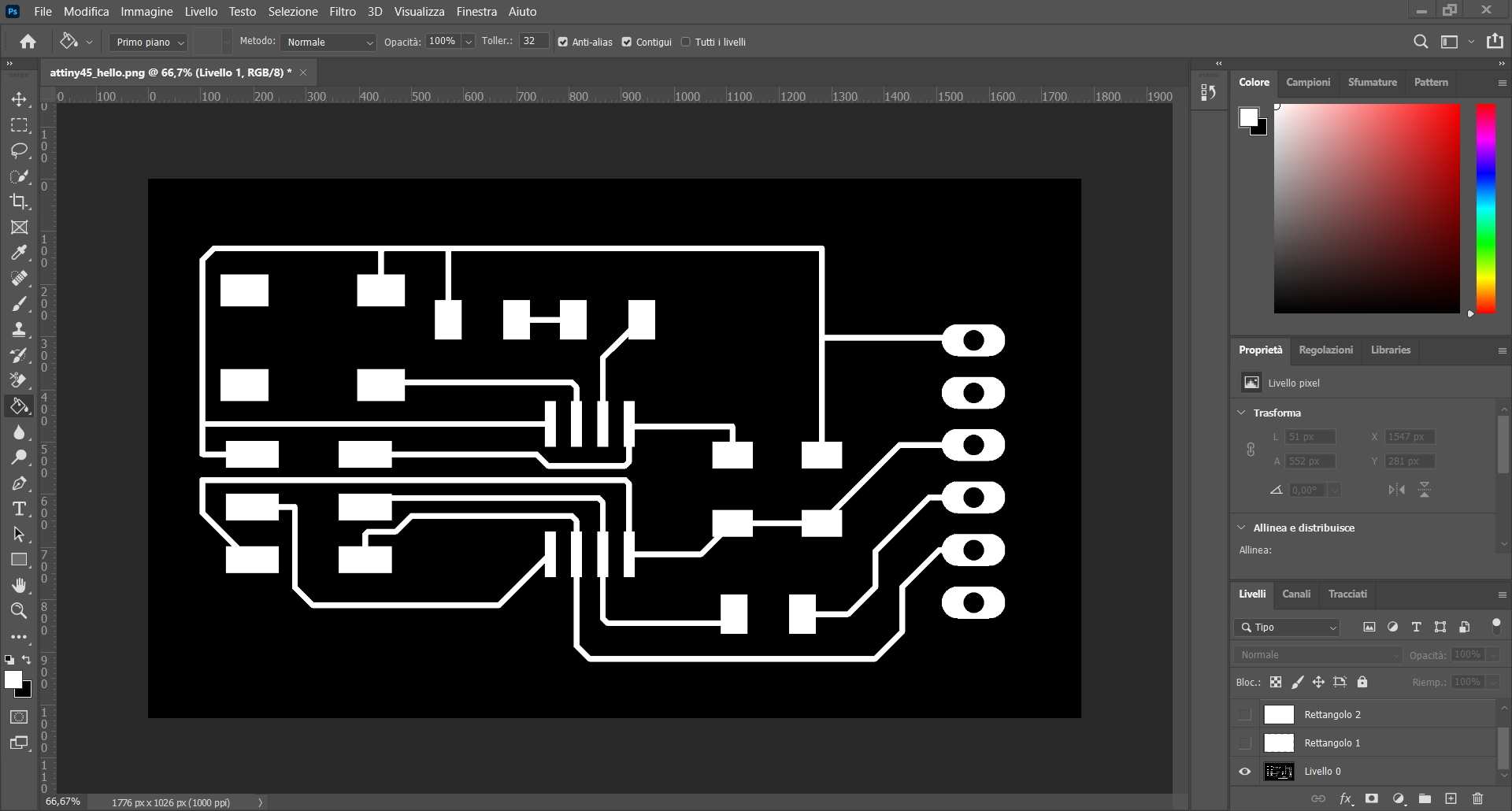
The image that specifies where the machine must drill the board holes so that the connector can go through it:
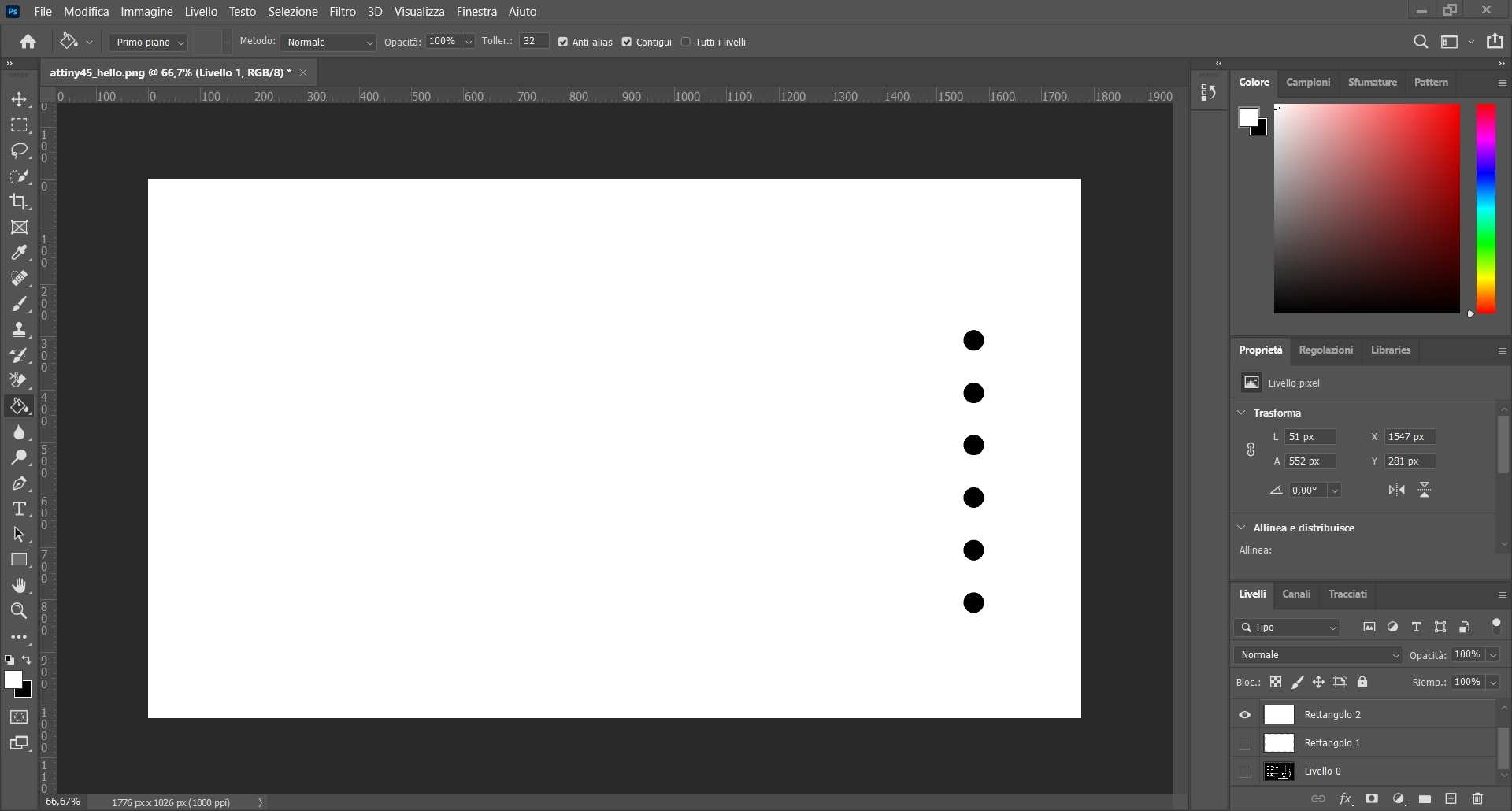
The outline, an image that guides the drill bit all around the board in order to define its borders:
Mods
Once the png files are ready, its time to create the rml files through mods. I double checked the three png dimensions towards being sure they were the same. I used the 1/64 settings for the traces and the 1/32 settings for both holes and outline. I set the XYZ origin to (0,0,0) and kept all the other settings unvaried.
Here you can download the rml files:
It’s time to mill!
Roland SRM-20
This is the machine so far I appreciated the less. Its parts are fragile, it is not easy to handle the components and while its working sounds unpleasant.
The first time I used it I almost broke it, this time nothing fell apart, but this doesn’t matter everything ran smoothly. In fact I had several complications.
Once the machine got set up properly, I started milling the wrong board. It is entirely my fault, I should have checked twice before starting the milling process.
So I ended up using more or less half of my copper board for someone else’s project. The milling process also had a Z axis problem (this is not the last time I am saying it today…).
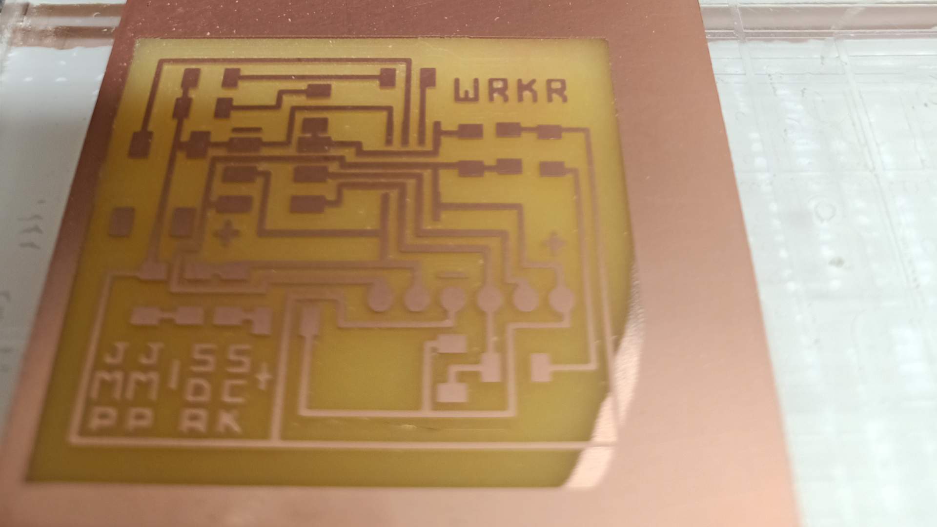
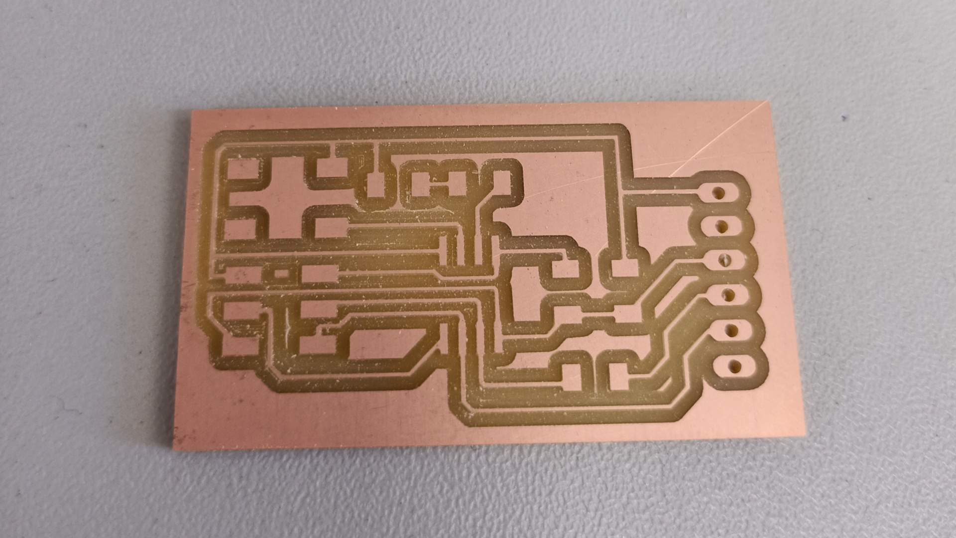
Once the machine had been set up, I ran the correct rml file and everything seemed alright for a while. By reason of the ruined sacrificial surface, I had to mill multiple times the PCB. At the end of every process, I set a new Z axis origin where the board kept being scrathed just superficially. After 4 or more milling processes, the board traces came out nicely. Then I changed the drill bit and cut the holes and the outline. This is the PCB right out of the machine:
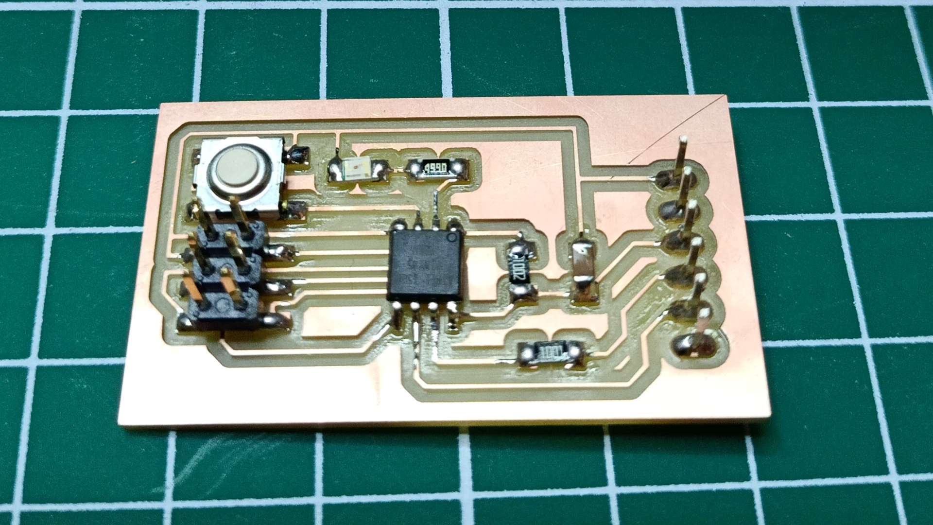
Soldering process
I made the bill of materials starting from the schematic I made, then I soldered all the components. This is the PCB with all the components:
Testing the PCB
I used the multimeter to check if all the wires connected correctly all the components, and they did.
Then I used the bench power supply to do a smoke test. The board did not overheat at all.
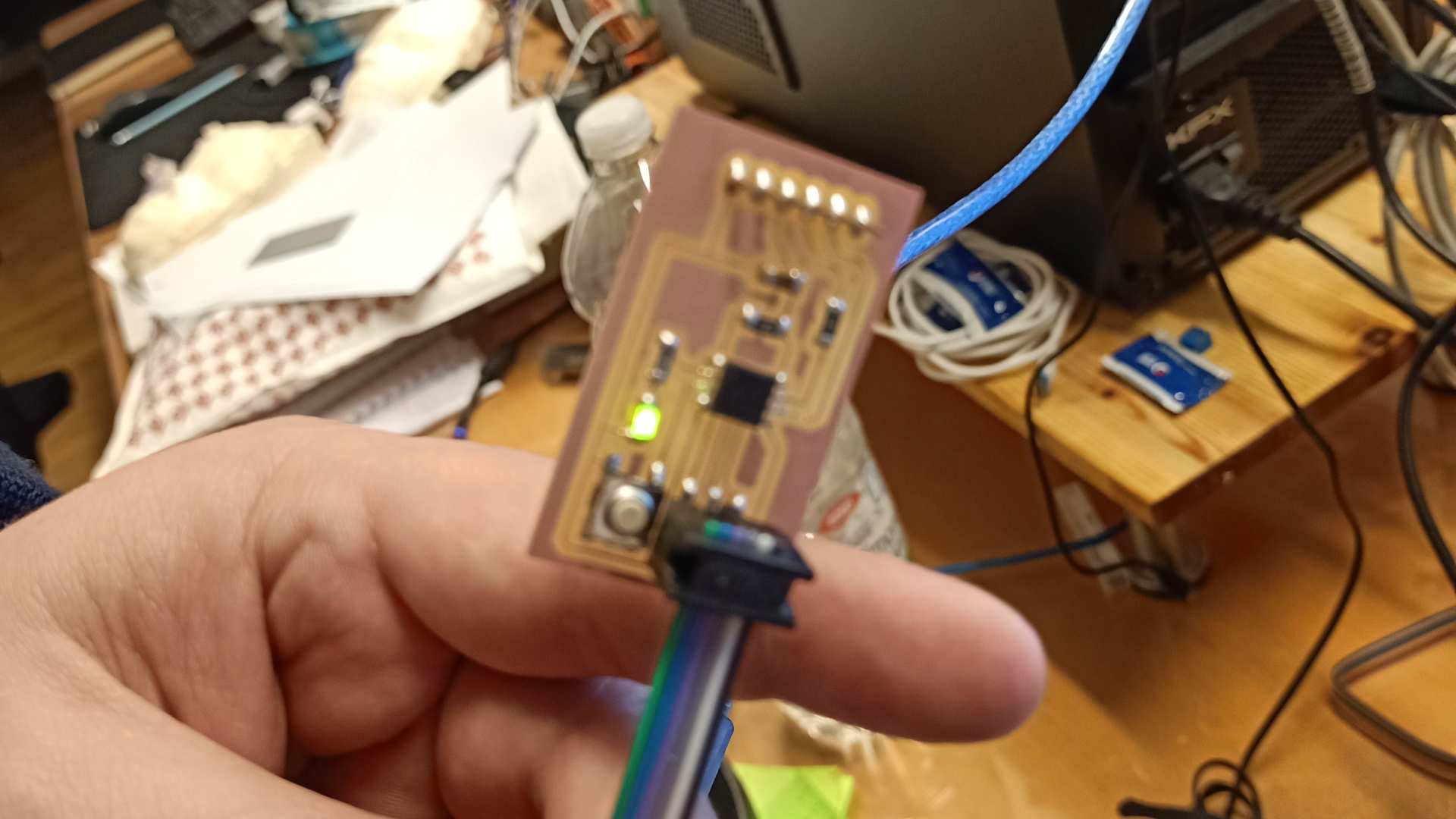
The last thing that had to be done was programming it towards checking if the components spoke correctly to each other. The first attempt gave me a rc = -1 failure message.

I started the debugging process along with my instructor (during the embedded programming week I’ll be on my own…amazing). We couldn’t find the solution. In the end he plugged the board again, and it worked!
This is the end of week 6 documentation.