Electronics Design
This is the assessment for this week’s module:
Group assignment
Use the test equipment in your lab to observe the operation of a micro-controller circuit board.
First of all, we listened very attentively to the instructions on the use of three test machines available in our lab:
- Power supply
- Oscilloscope
- Signal generator
Then we tested a circuit using this equipment to see how it works and how it changes in function of different LEDs on the board, that is different voltage needed in order to light up the Led, and signals generated through a generator device.
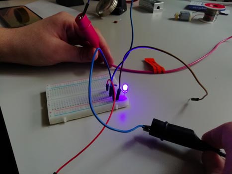
Our lab is provided by an adjustable power supply, which means that it permits to program, using mechanical knobs, the voltage and amperage of the output. Generally, this device allows the transmission of electric power to an electrical load converting current coming from a source to the programmed frequency, voltage, amperage. Our device has two channels, we used the second one so the Ch2, the black wire we connected to the ground in our circuit and the red one to VCC since it was the positive charge and pressed “output” to enable the current supply flow.
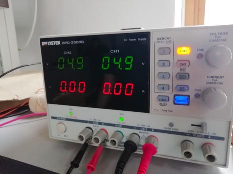
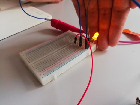
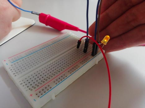
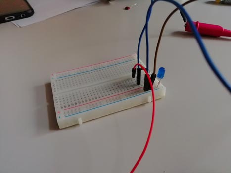
So we had several tries with a blue Led on our bread board and then with a yellow one. To start we programmed 4.9 V and it worked with both Leds. Eventually we switched it to 2,5 V and whereas the yellow light was quite strong, the blue Led was much softer. With 1,9 V it did not work at all with blue, but generated a mild yellow light with another Led.
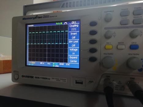
This test instrument in our lab has four components:
- The display
- Horizontal knobs which enable to control the time base or the sweep line
- The vertical segment sets the amplitude of the displayed signal
- Trigger section which regulates the starting point of the sweep
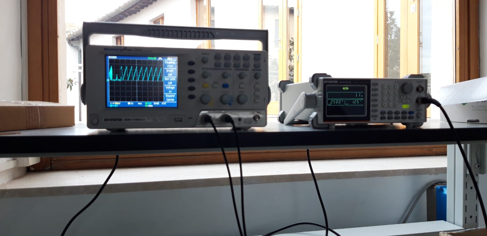
The Oscilloscope is a electronic device that shows via a waveform on a display varying signal voltages and helps to analyze frequency, amplitude, time interval etc. For this reason, in this session we used it mainly in conjunction with logic analyzer.
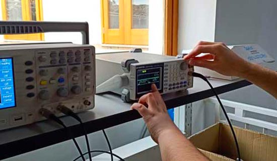
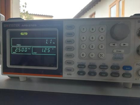
Easily to figure out from the name, this instrument generates electronic signals creating the specific waveform output as needed setting waveform parameters, including waveform type, frequency, amplitude. It might be helpful to use this device to test, but also debug created circuits. In our case, we used it to generate a couple of signal types to see how the output changes setting 1.1 Herz, also on the display of oscilloscope.