Computer Controlled Cutting
This is the assessment for this week’s module:
Group assignment Characterize your lasercutter’s focus, power, speed, rate, kerf, and joint clearance document your work (individually or in group).
The first thing we had to do, once the machine has been set up, was to create a matrix.
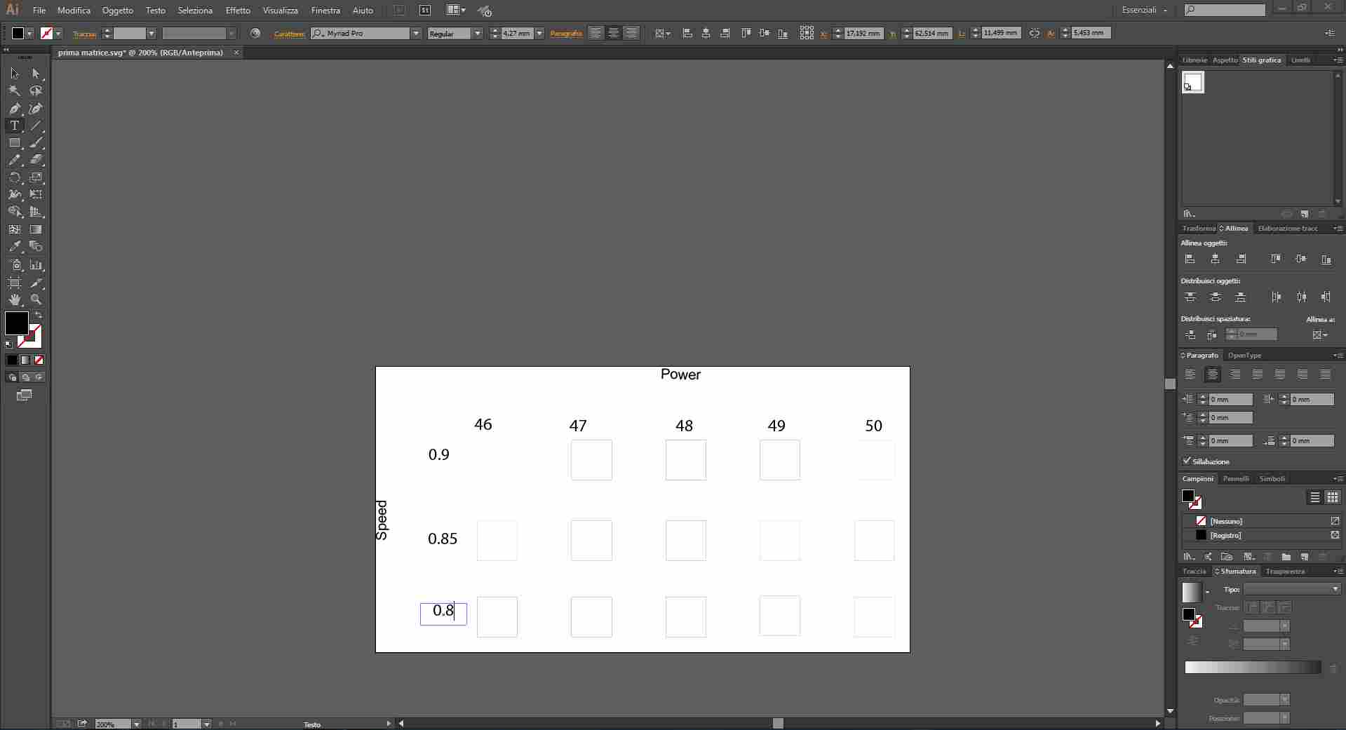
This matrix could help us individuate the best setup in terms of speed and power for the laser cutter. We had to create 3 tables, each one made of 5 different power settings and 3 speed settings.
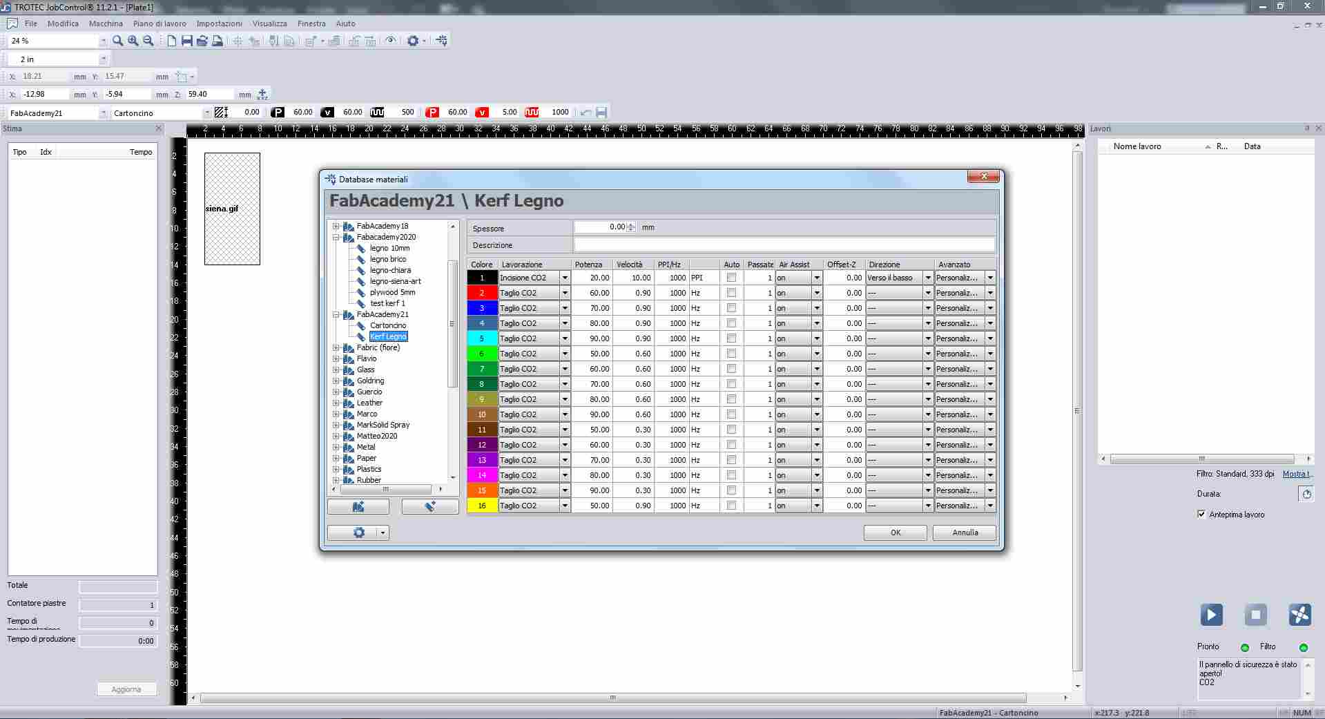
The first table has been the most wide in terms of power: we had to caliber the power settings, aiming at a narrow gap between the values. The first table had power values going from 50 to 90. The speed values were the following: 0,90; 0,60; 0.30. After the first results, in the second table we refined the values and moved to a narrower power gap: from 40 to 60. The speed values also changed, in the second table they went from 0.90 to 0.70. The last table allowed us to find the proper settings: our laser cutter is going to cut our wood panels with 50 power at 0,90 speed. (A lower power can do the job if the pieces are really small, but 50 power is more effective on wider surfaces and is still a low value in terms of efficiency).

This measurement took us several time, we started from two different approaches:
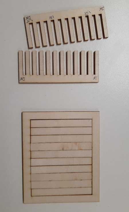
- Cut ten rectangles, pull them together and measure how much space is between the last rectangle and the outer frame. Dividing that number by ten gives us the average Kerf.
- Cut two “comb-shaped” figures, each gap between two teeth has a different size. Combining the two combs it is possible to obtain the proper size in order to grant a good grip between the surfaces.
We used Fusion 360 and drew the 2D sketch. Then we moved on with Adobe Illustrator. Once the rectangles have been cut, we used the caliber to measure the difference between the total surface of the rectangles and the inner part of the frame that contained the rectangles. The caliber did not immediately gave us a clear result since wooden surfaces are quite fragile under the pressure of a metallic caliber. After a while we were able to obtain a few constant results in a row. The resulting Kerf we had is 0.11mm.
We struggled at the beginning in order to get a parametrical structure for the combs. Sticking with Fusion 360, we finally succeeded in the making of the figures. Since we’ve measured the whole panel’s surface, we obtained an average panel width, but the initial measurement did not help as much as we hoped. The combs' teeth actually required less space and so most of the bigger teeth were useless. Despite the unused bigger section, the small one did the job: the resulting Kerf from this method is 0,15mm.
One Kerf to rule them all, one Kerf to find them, one Kerf to bring them all, and with the laser cut them
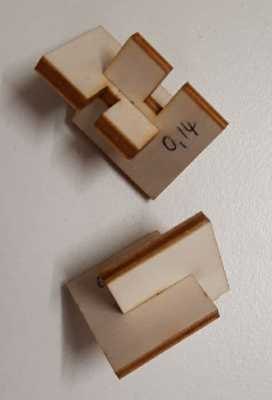
We definitely struggled to obtain a kerf measurement that could grant us a universal-ish push-fit cut all along our panel. We started using the result that came out of the first approach but the bond was too loose, so we started raising the Kerf up to the result provided by the combs. This second Kerf gave us a tight bond, so tight that the wooden pieces broke apart. From that result, we moved backwards from 0.15mm to 0.11mm, We drew shapes with 0.14mm and 0.13mm. The latter seemed still too loose, but a 0.14mm Kerf seemed perfect.
“A Kerf that stands four or more press-fits, is a good Kerf."
The files we made can be downloaded here:
- [Kerf rectangle approach](inserire link repository online)
- [Kerf combs approach](inserire link repository online)
- [Kerf pieces for checking](inserire link repository online)
- [Matrix](link repository online)