13. Outputs
This week I work on my outputs for my final project. It is a really mess in my head… But I try to not giving up… This assignment will be the sum up of what I get from now.
Some questions:
What is the difference between microcontroller and microprocessor?
From electronicaltechnology.org:
What is a Microcontroller?
A microcontroller is a mini-computer on a single semiconductor IC (integrated circuit) chip. It is a complete computer and has all the essential components needed on a single chip such as the processing unit, ROM, RAM, I/O ports, serial ports and Timers, etc.
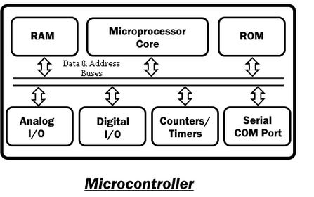
It does not need external components to perform a task which makes it a perfect candidate for embedded and compact devices in industries. Most common series of the microcontroller are PIC, 8051, AVR, etc. Example: arduino
What is a Microprocessor?
A microprocessor is an IC that has only CPU (Central processing unit) without other necessary components inside the (IC) packaging. Its packaging does not contain RAM, ROM and other components required to perform a task. That is why it needs external components to complete a task.
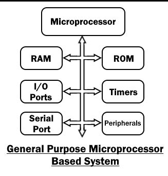
Due to this reason, the devices made from microprocessors are bulkier and power consuming but they have up-gradable memory and high processing capacity for performing complex tasks such as games, website and software development, etc. it functions are unlimited. example: computer,install windowns, reprogrammable, dynamic frame, Ram, own programs.
| Microcontroller | Microprocessor |
|---|---|
| It is a mini-computer capable of performing a task on its own. Examples: 8051, 8951 etc. | It is the central processing unit of the computer. Examples: 8085, 8086 etc. |
| It has necessary peripherals inside the chip like RAM, ROM, etc that is why it is called SoC (system on chip). The functional units are registers, CU, ALU, RAM, ROM, IO Ports, DAC, ADC, Counters and Timers. | It needs external RAM, ROM to perform a task. The functional units are registers, CU and ALU etc. |
| It is used in the embedded system and specific applications. | It is used in computers as it is the brain of a computer. |
| It is used in compact devices because it does not need external components. | It needs external components thus the devices made it are bulkier. |
| Due to a few numbers of external components, the power consumption is very low. Thus it can be powered using batteries. | The external components require extra power to perform. Thus they are not suitable to run on batteries. |
| It has an internal fixed amount of memory that cannot be upgraded. | The external memory is upgradeable and can be easily varied to meet the task. |
| Due to on-chip flash and memory, they are fast in loading the program and instructions. Hence fast execution at startup. | Due to external memory, the programs take some time to load which makes it relatively slow. |
| The microcontroller also has a power-saving system for the idle condition that decreases the power consumption | The microprocessors do not have the power-saving function, they consume energy in idle condition. |
| Its processing speed is 8Mhz to 50Mhz. thus it cannot be used for complex tasks. | While the microprocessor processing speed is above 1Ghz. It can perform complex tasks. |
| The MCU can support upto 720p High-definition video. | It can support above 720p high-definition video. |
| It can support USB 2.0 with max speed of 480 Mbits/sec | While it can support USB 3.0 with 5 Gbits/sec speed. |
| The MCU is application-specific i.e. it is designed for performing a single specific task. | It is designed to perform complex and complicated tasks to utilize its high memory. |
| It is cheap and having low power consumption thus they are perfect for cost-effective, battery-operated electronics. | It is expensive and power-consuming having high processing speed thus they are perfect for high performance of complex tasks. |
What I need to make my projects movable:
The main thing of the eyes mechanism is the servomotors.
Adafruit 16 channel pwm servo driver.
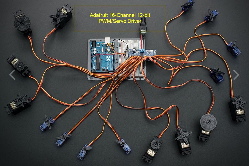
Servo motors requirements are: Voltage: 4,8V Current: 1A.
The computer delivers 5V, 0,25A to turn on the arduino board. We need more power.
solution 1:
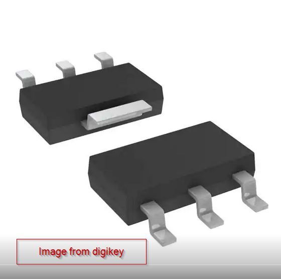
In la Machinerie, there is a 12V 1A DC supply, so we need to install a regulator.
NCP1117ST IC reg linear 5V 1A sot 223
 datasheet
solution 2:
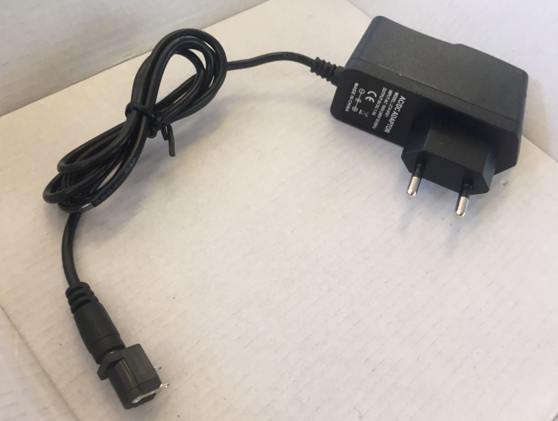
DC 5V 1A supply . And I get this one.
On my board, I will give options to add the inputs from week 11.
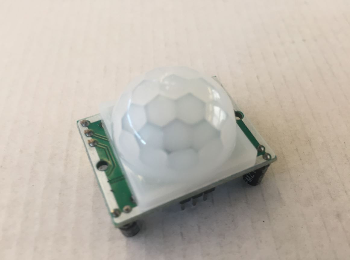
joystick, potentiometer, IR Hc SR01 move sensor mouvement.
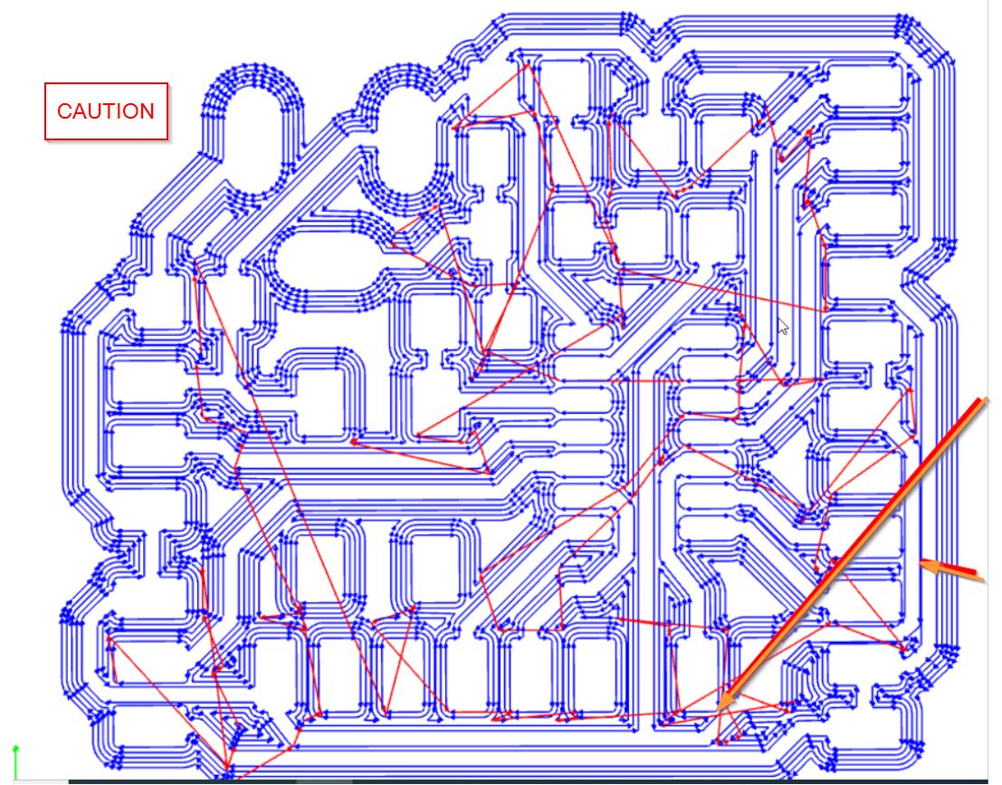
Caution:
///////////CAUTION/////////// A “current increase” could be generated from the 5V DC supply to the 1A current from the programming USB part(0,25A). The microcontroller Attiny 1614 could be damaged. We need to remove +5V from the FTDI and UPDI leads.
//////////CAUTION/////////// Sylvain advices me to wide the trace up to the servo board.
/////////CAUTION///////////// The DC power must be far from the communcation (tx, rx,updi)
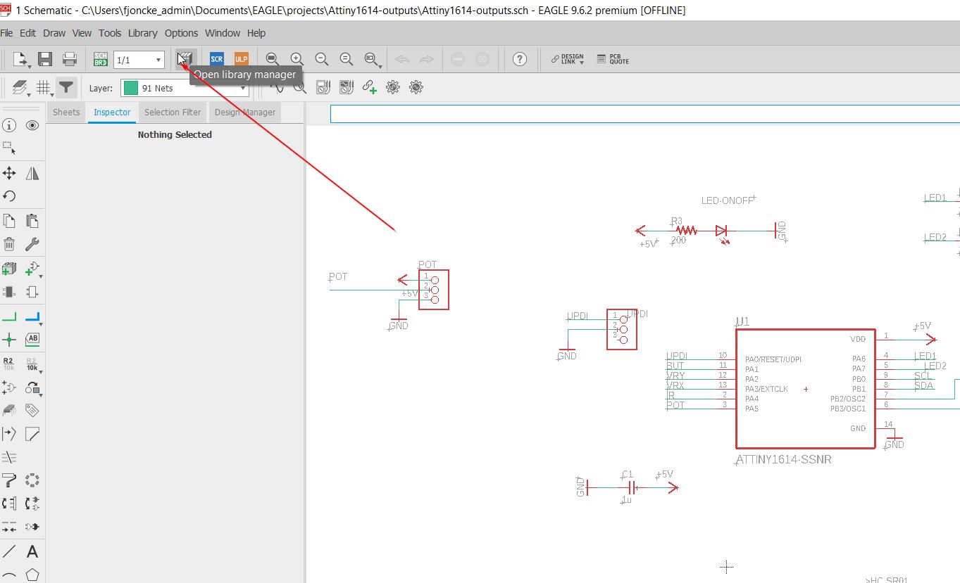
Back to Eagle:
Each time, I am learning new stuffs from the Eagle software and electronics, thanks to Sylvain Robert, Jules Topart, and Axel Chemin, Johnny Gouvaert and Arthur Vercaemst from my school. I have documented the whole process as a reference for my future project.
01.Creating new devices.
I explain how to create new devices for my board.
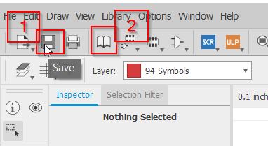
Open the library manager.
Edit the fab library.
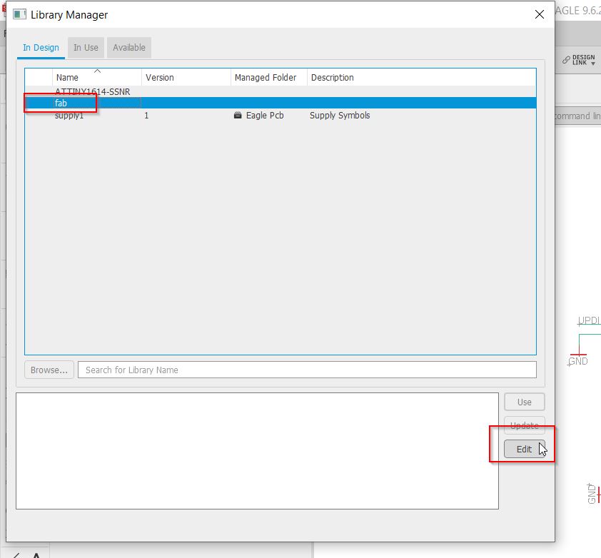
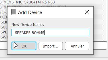
Add a device.
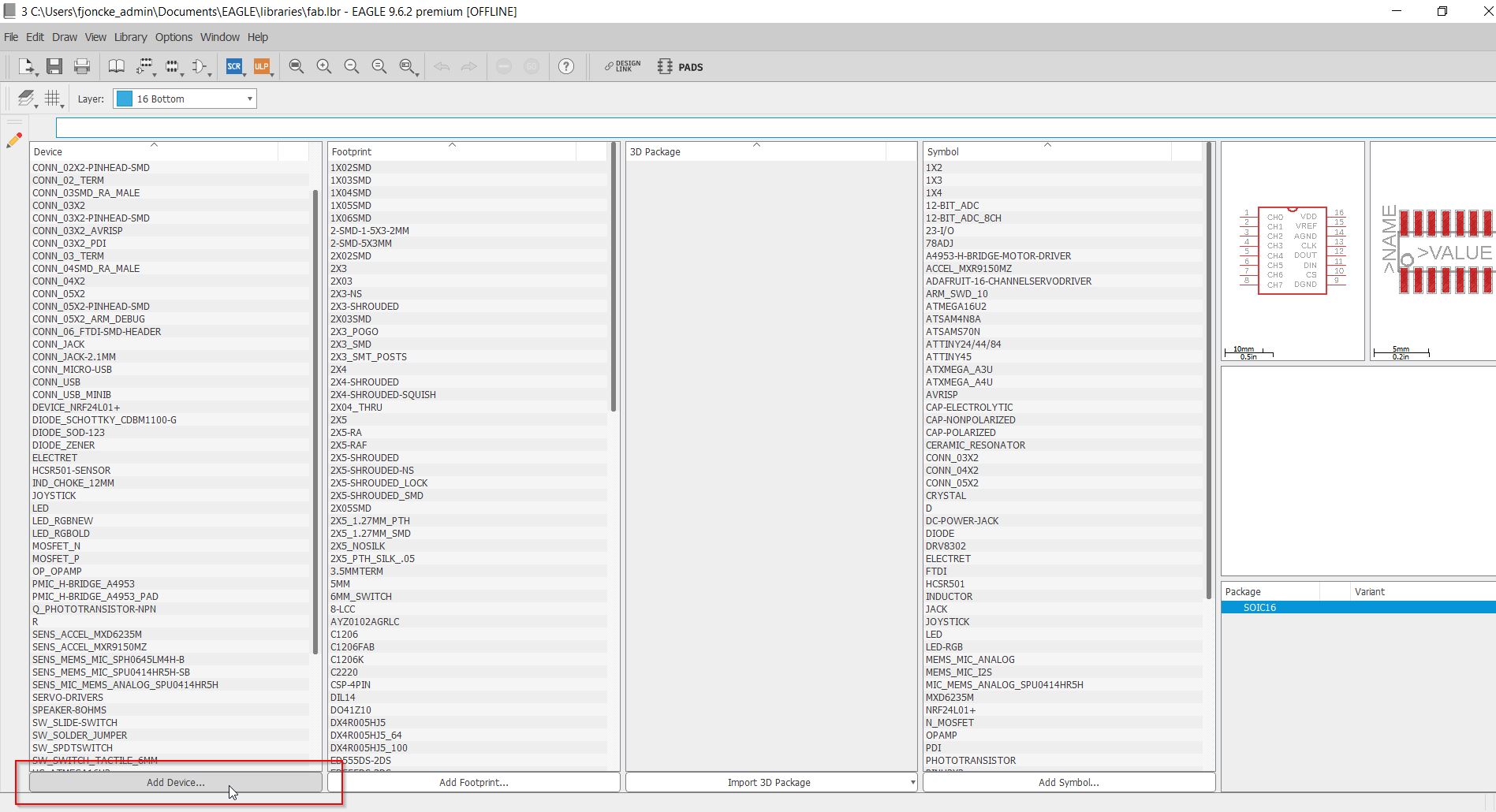
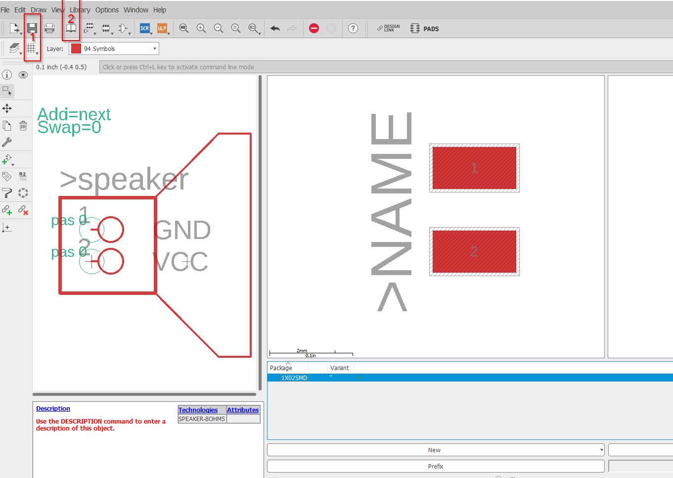
I am creating a speaker.
_The symbol I want is simple and based on the 1x2 symbol.
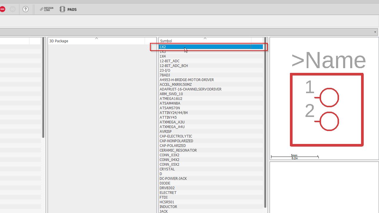
Duplicate the 1x2 symbol
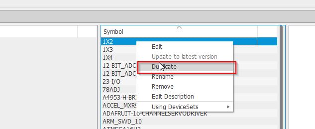
Then, edit this new symbol
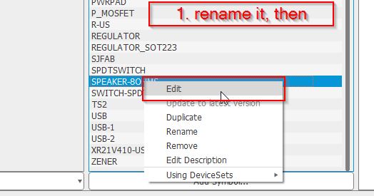
Use the design tool to make your own symbol
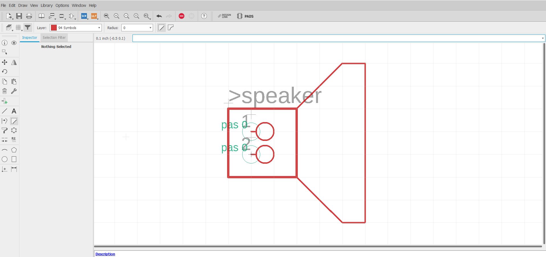
Save and go back to the library.
Edit the new device
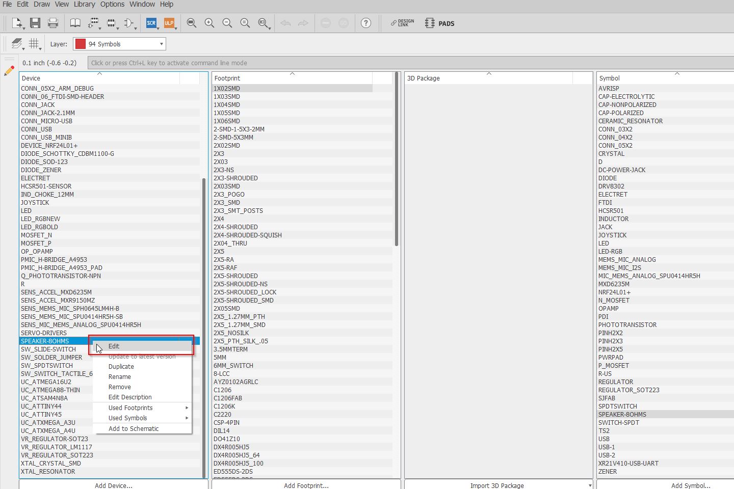
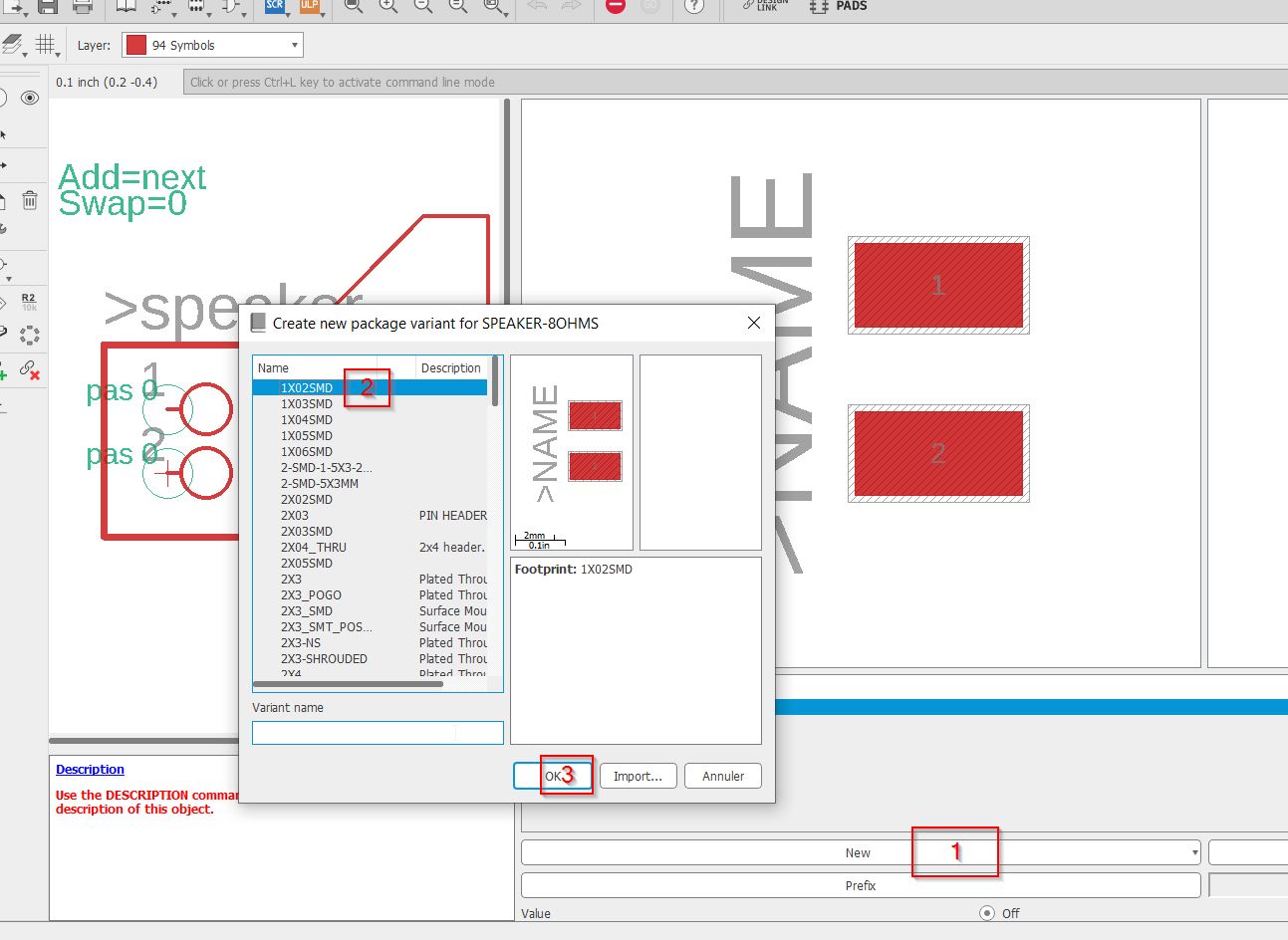
I use a footprint from the local package.
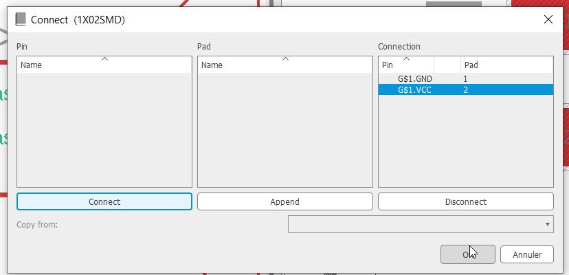
The pins have to be connected to the proper pads.
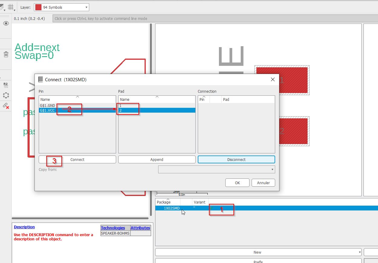
You validate once name columns are empty.
Save and go back to the library manager.
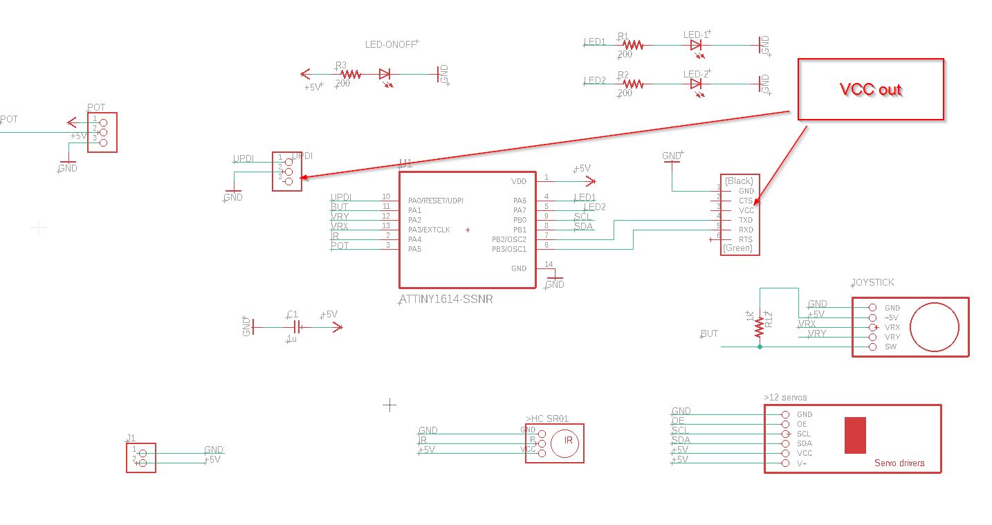
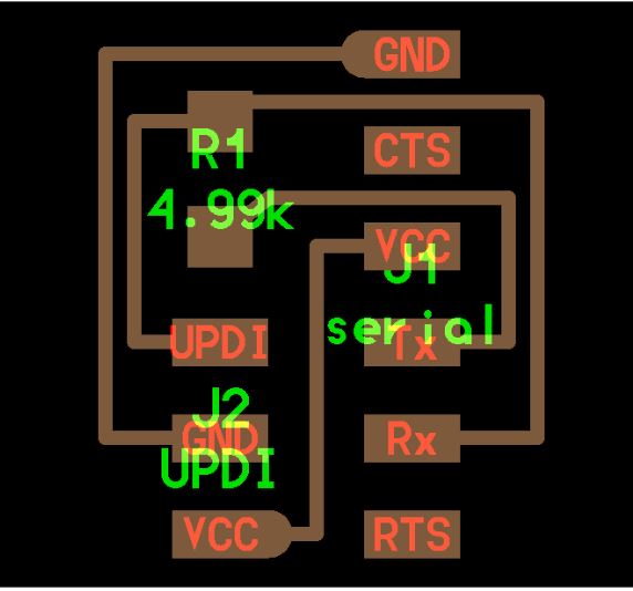
Right now, I have this schematic.
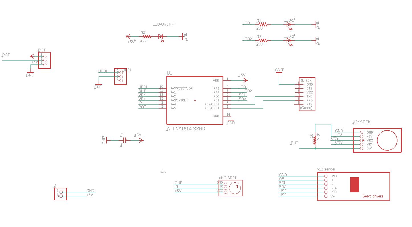
Talking to Sylvain and Jules, they advised me to remove the VCC from the comunication. Beacause the “+5V” from the 5V external supply and the VCC from COM will lead to a electricity conflict.
Here we go! Let’s creating the new devices:
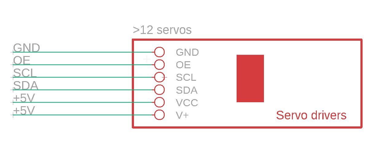
_ Adafruit 16-Channel 12-bit PWM/Servo Driver aka…_
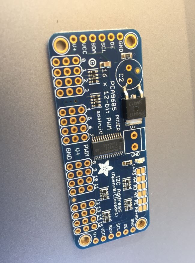
_…”Servo drivers”.”
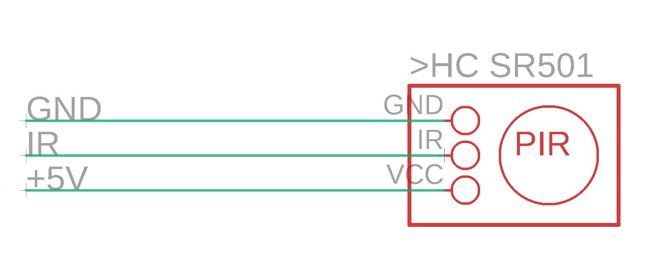
The IR sensor device called HC SR501.
_The 5V supply 1A.
 There are 3 pins, one for (+) , one for (-) from battery supply, another (-) for the dc supply. It is called the switched jack.
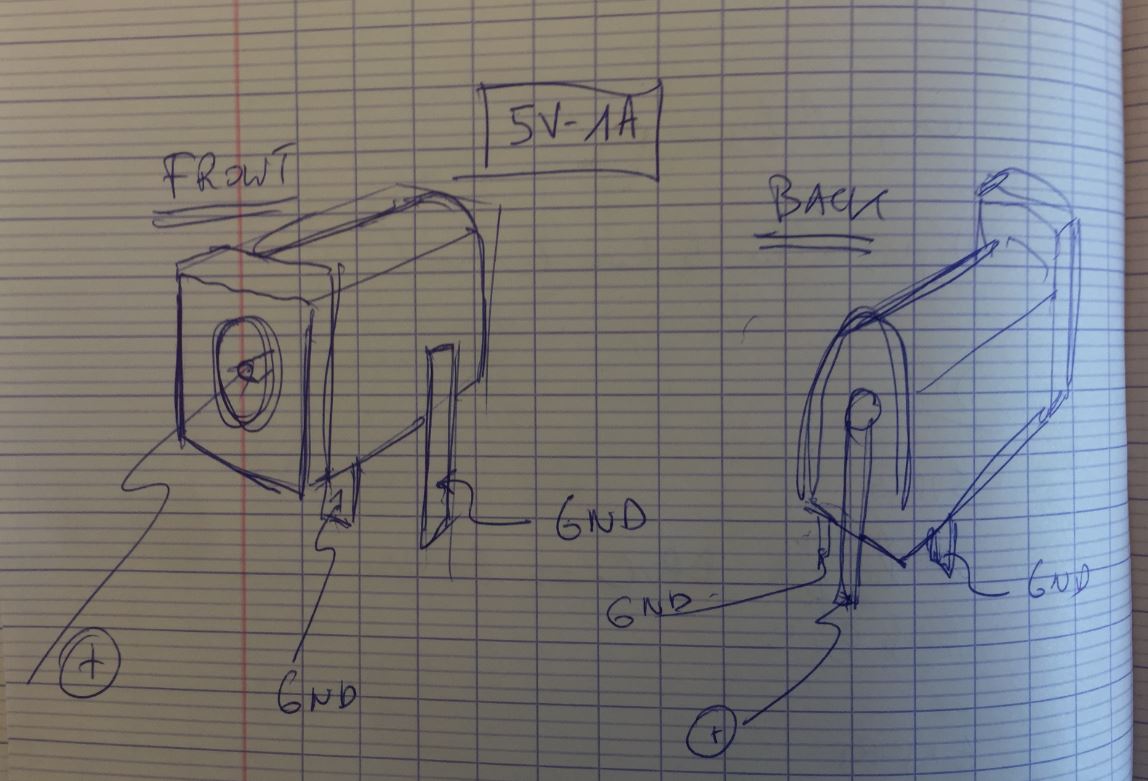
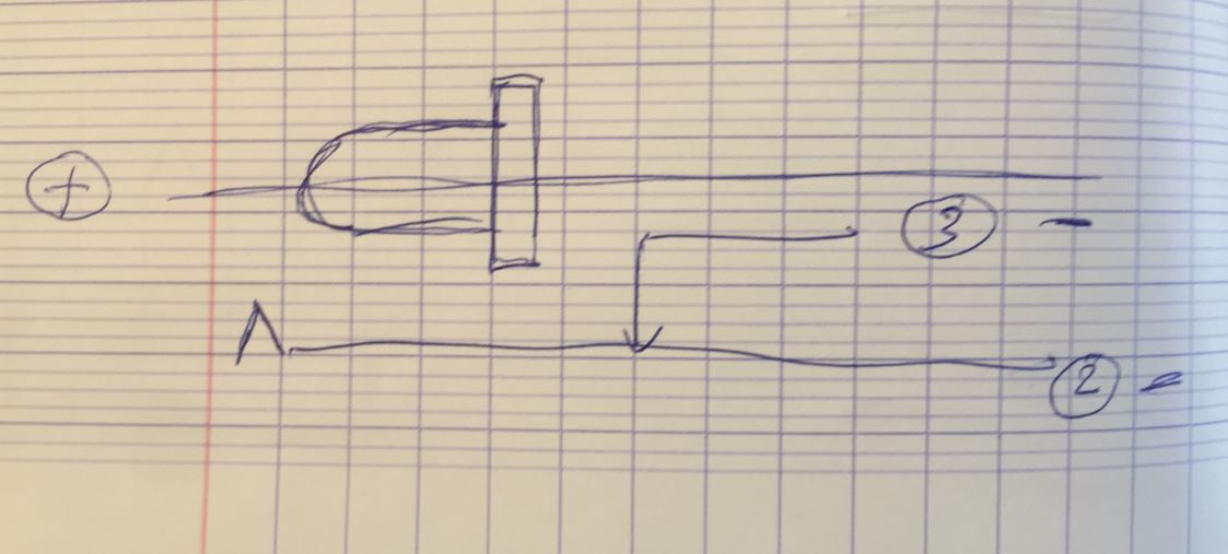
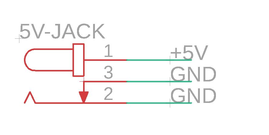
- Switched Jack
Extract from Glorfingel. When you insert the plug, the connection between pins 3 and 2 breaks. This is useful for cutting a battery out of the circuit when a DC adapter is plugged in. Imagine you have a battery which is grounded via the 3-2 connection. When you plug in, 3-2 breaks and so the battery’s ground connection is lifted. Now the battery is protected from two unwanted actions: discharging, and being charged. (It’s still a good idea to put diodes in the circuit in case the switch fails for whatever reason.) Or, this can be used for building a circuit which detects the insertion of the DC plug. For instance, when the 3-2 connection breaks, some microcontroller I/O pin could be pulled up to VCC, and then the firmware knows that the device is on an adapter. If you don’t take advantage of this, you can leave pin 3 unconnected in your PCB, or you can ground it so that it is permanently connected to 2.
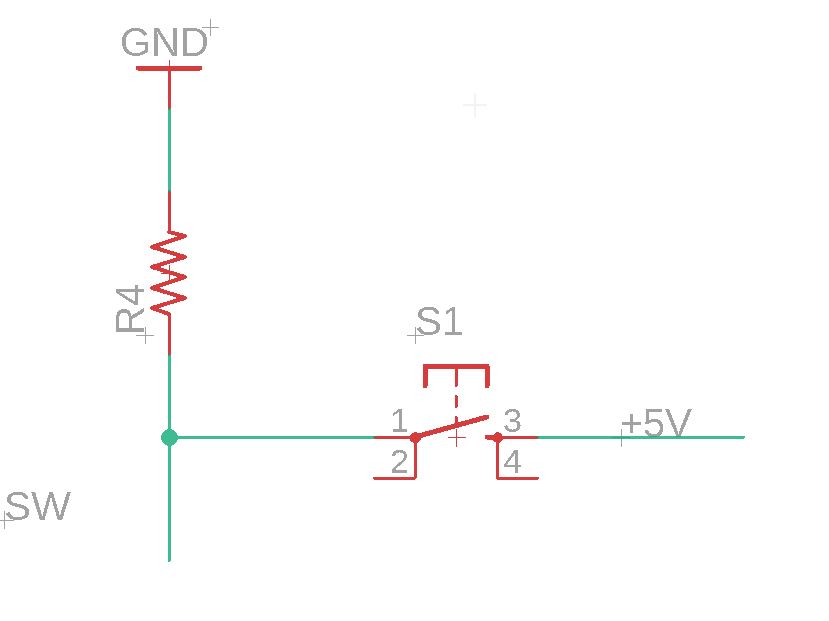
Here comes the switch button.
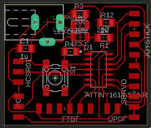
My last version of the schematic:
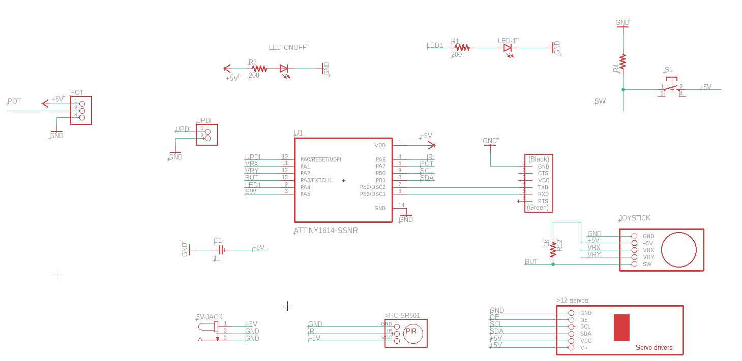
The devices take place according the the position of the Attiny1614 pins.

After Autorouting, and fixing couple of wrong paths.
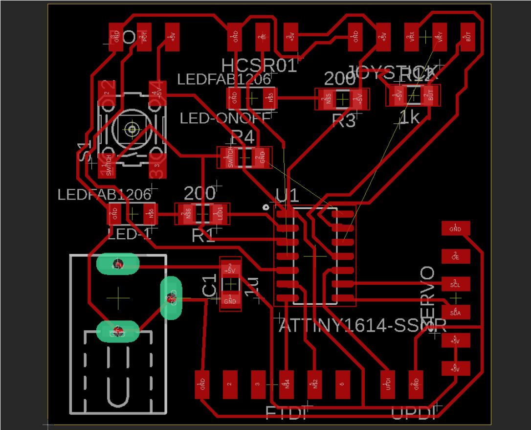
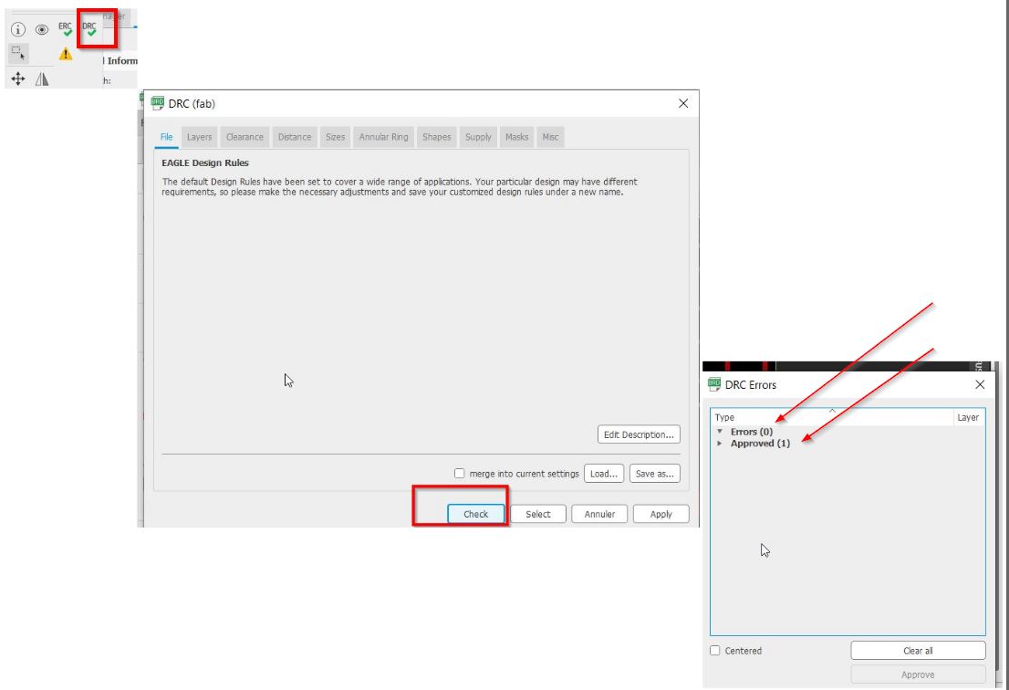
_Design Rules Check from fab. I got one because of the DC Ground. There are some devices connected to the battery (-) and some to the DC (-).
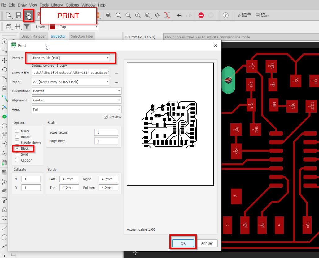
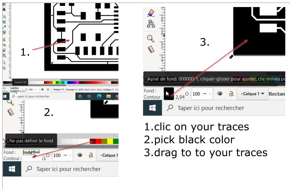
To get the traces, you make what you want visible.
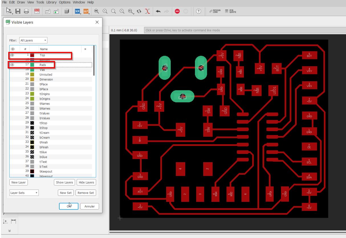
Jules told me that it is easier to make pdf instead of export pngs.
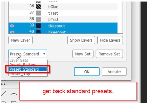
Once you are done with the traces, you can get your standard presets to avoid missing any layers.
INKSCAPE
Open your favorite 2D graphic editor and import your recent file.
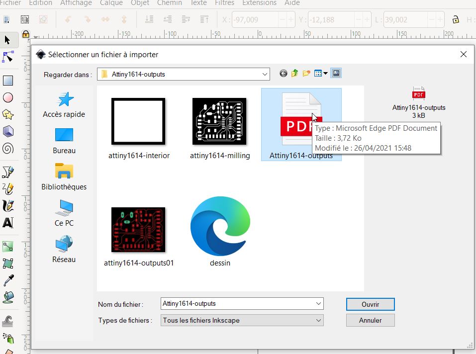
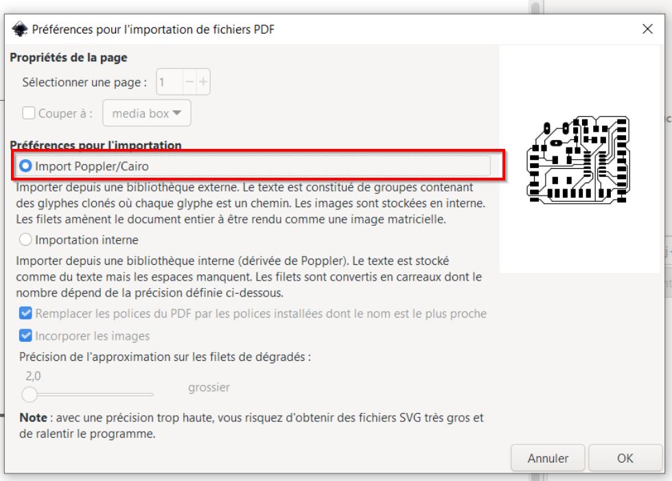
You need to get this selected preferences to import.
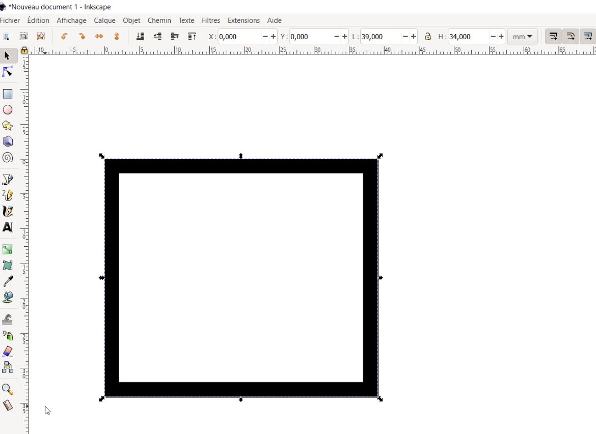
My board is 35x30 mm. According to the interior you need to add 4 mm out.
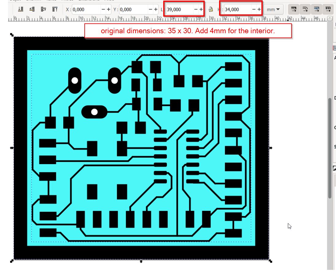
Make the workspace fitting your board.
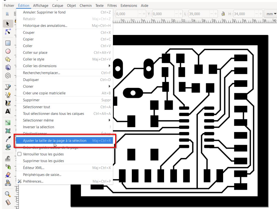
This is a tricky step:
Export as a png file.
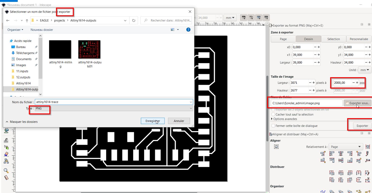
Repeat for the interior milling.
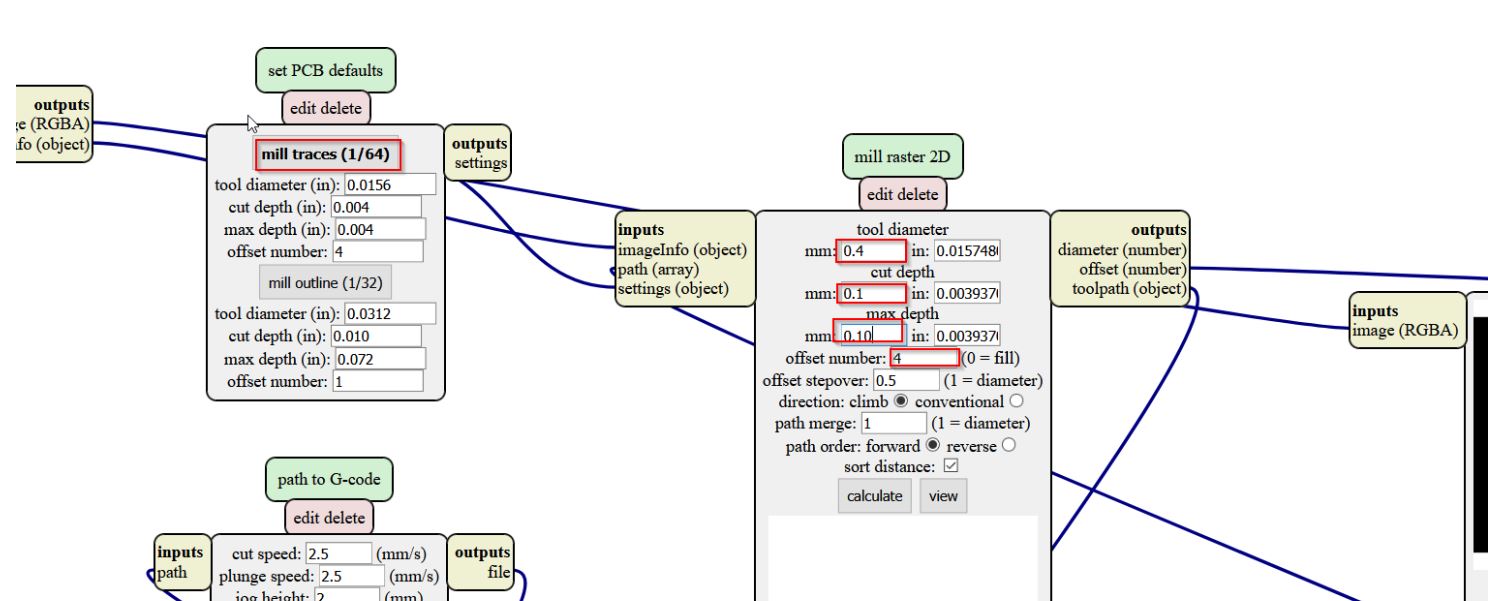
MODS
Now you just open MODS
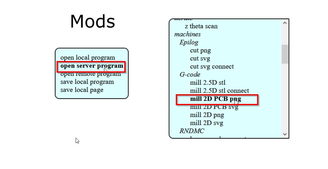
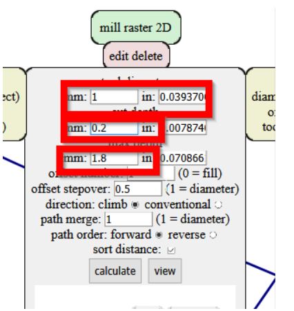
Firt, we mill traces and change the mill raster 2D parameters:
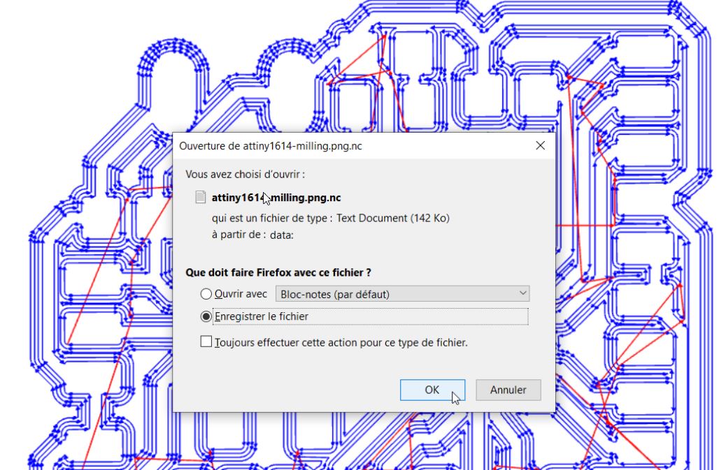
 Open the previous files called “atttiny1614.milling.png.nc”:
Check your paths out. I had some failures, 3 pins are still connected.
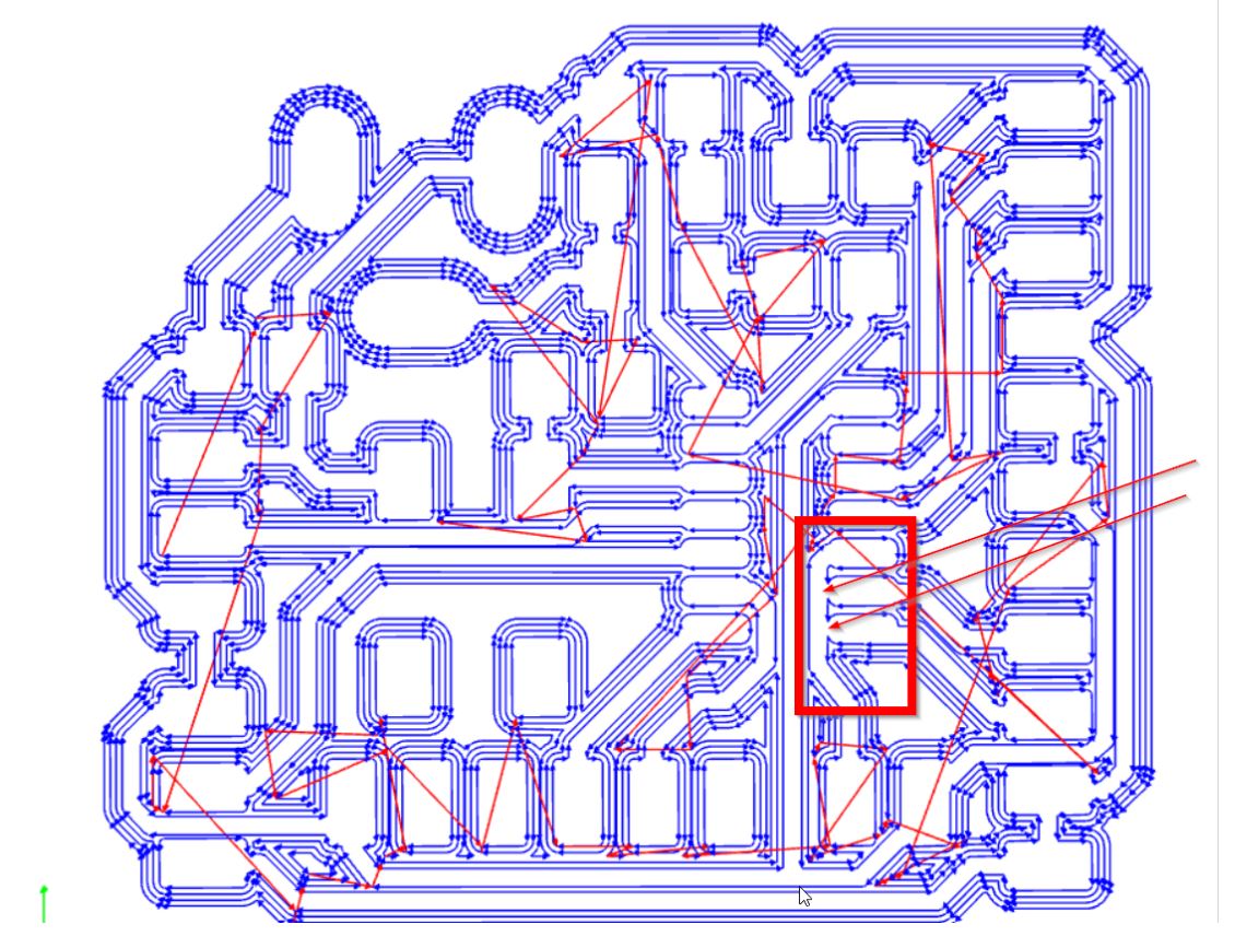
I removed on the left the traces.
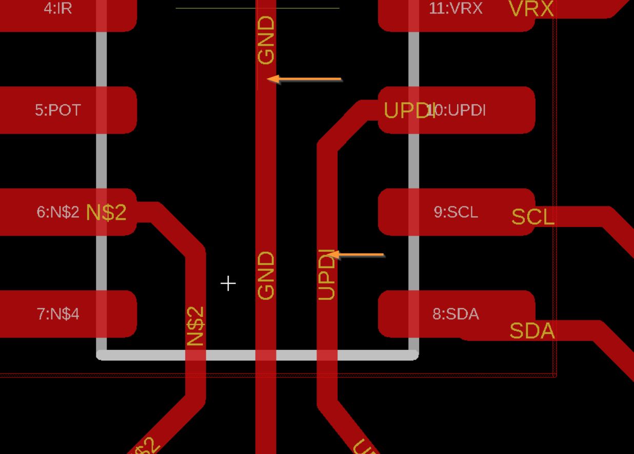
My buddies prevent me from too thin paths.
After that, you can upload your gcode for the traces.
I take car of the interior for the next step:Mill outline
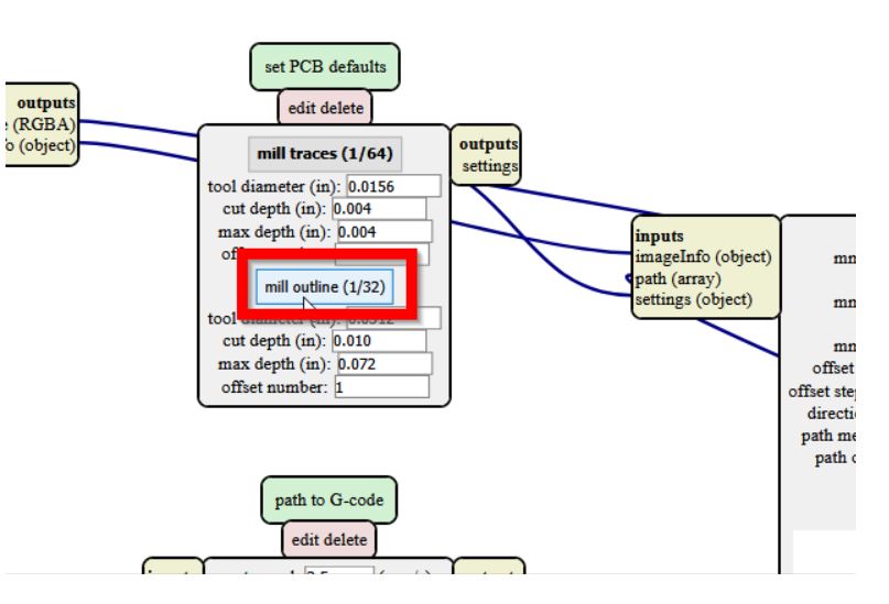 We need these 3 parameters:
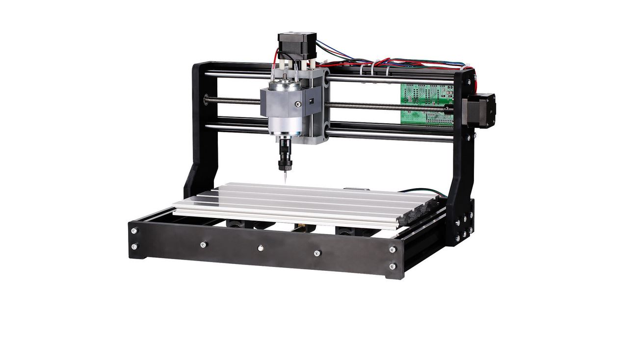
Sainsmart CNC machine
SainSmart Genmitsu CNC Router 3018-PRO. website
| SPECIFICATIONS | CNC router |
|---|---|
| Effective Engraving Area: | 300 x 180 x 45 mm(11.8 x 7.1 x 1.8”) |
| Frame Size: | 400 x 330 x 240 mm(15.7 x 13.0 x 9.4”) |
| Frame Material: | Aluminum |
| Axis Bracket Material: | PF |
| Z-Axis Component Material: | Nylon |
| Spindle: | 775 motor, 12V, 3000 RPM; 24V, 7000 RPM; 36V, 9000 RPM |
| Rated Power: | 60W; Maximum Power: 120W |
| Step Motor: | 1.3 A, 12V, 0.25 Nm torque (2.2 in lb) |
| Drill Bits: | Tip 0.1 mm, 20 degrees, Diameter 3.175 mm |
| Supported OS: | Windows XP, Windows 7, Windows 8, Windows 10, Linux, Mac OS |
| Software: | Grbl control(Candle) |
| Power Supply: | 24V/4A |
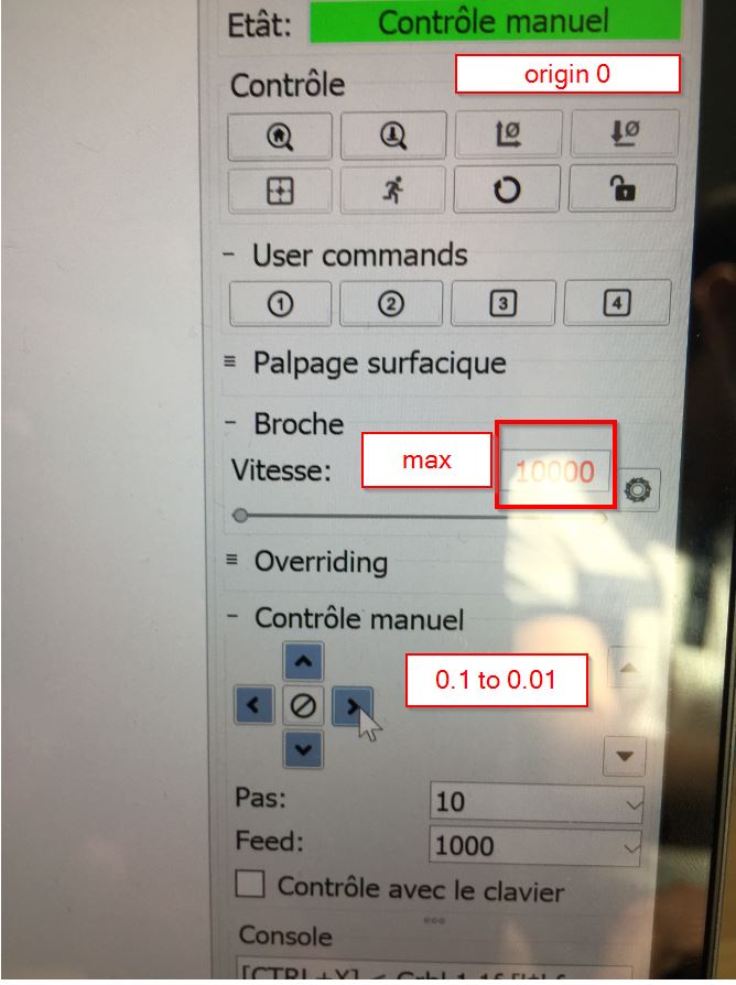
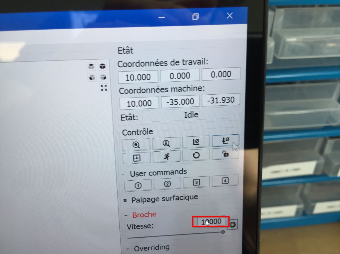
You can get the gerbercontrol software on this link to control your cnc router. You need to set up the x0y0 and the z0.
check it out the spindle speed. Come z gently to the board. Start from 1mm to 1mm. When you are close, go to 0,1 to 0,1
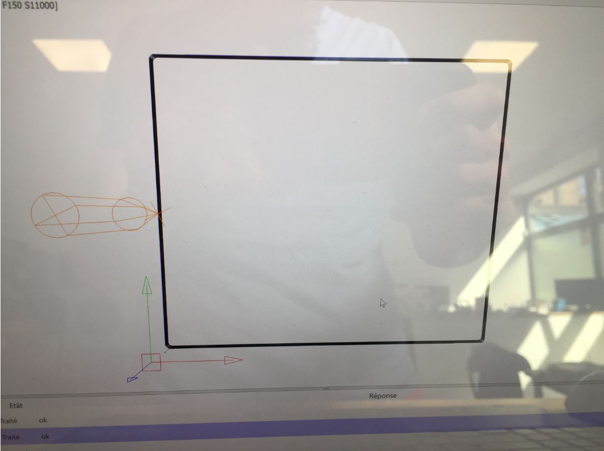
 This is the plan:
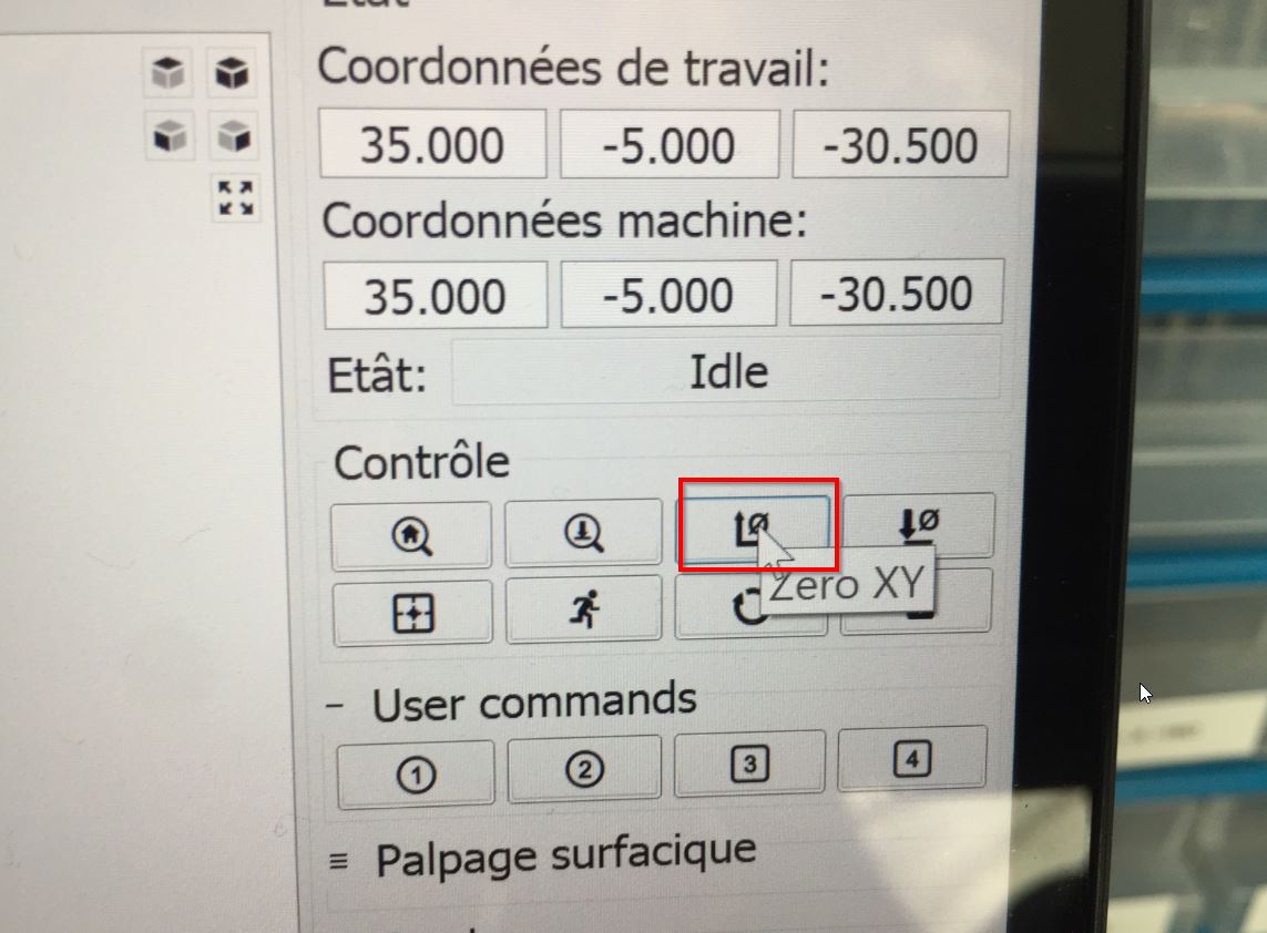
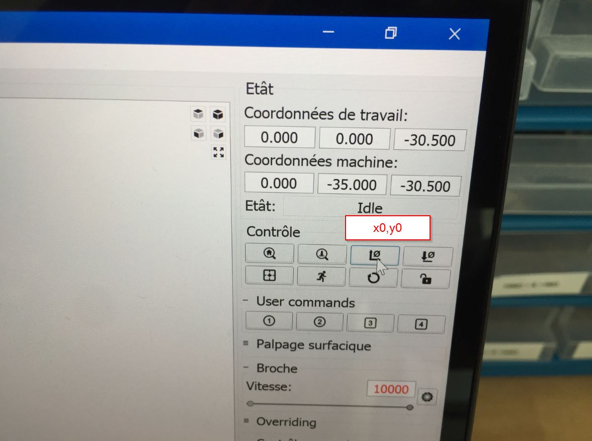
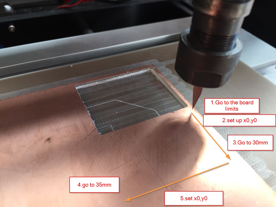 2.set X0,Y0 up.
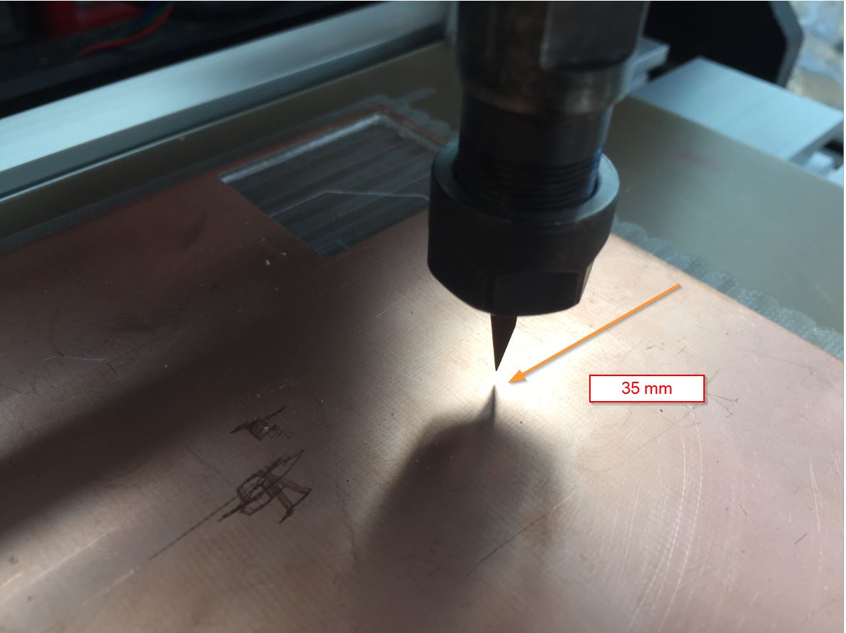
3.Go to 30mm.
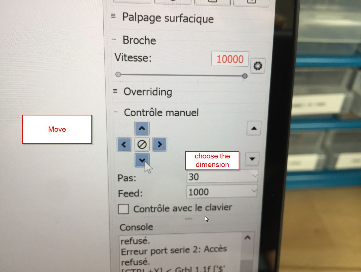
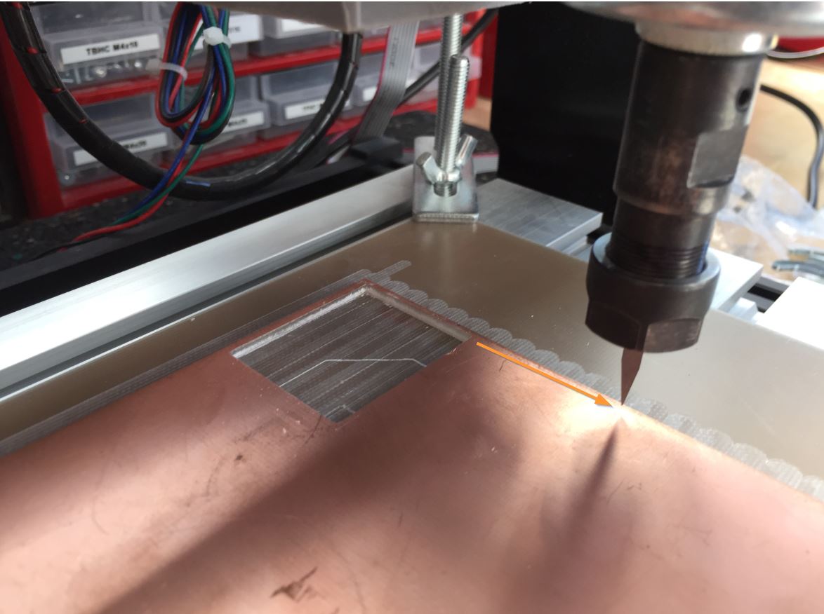
4.Go to 35mm.
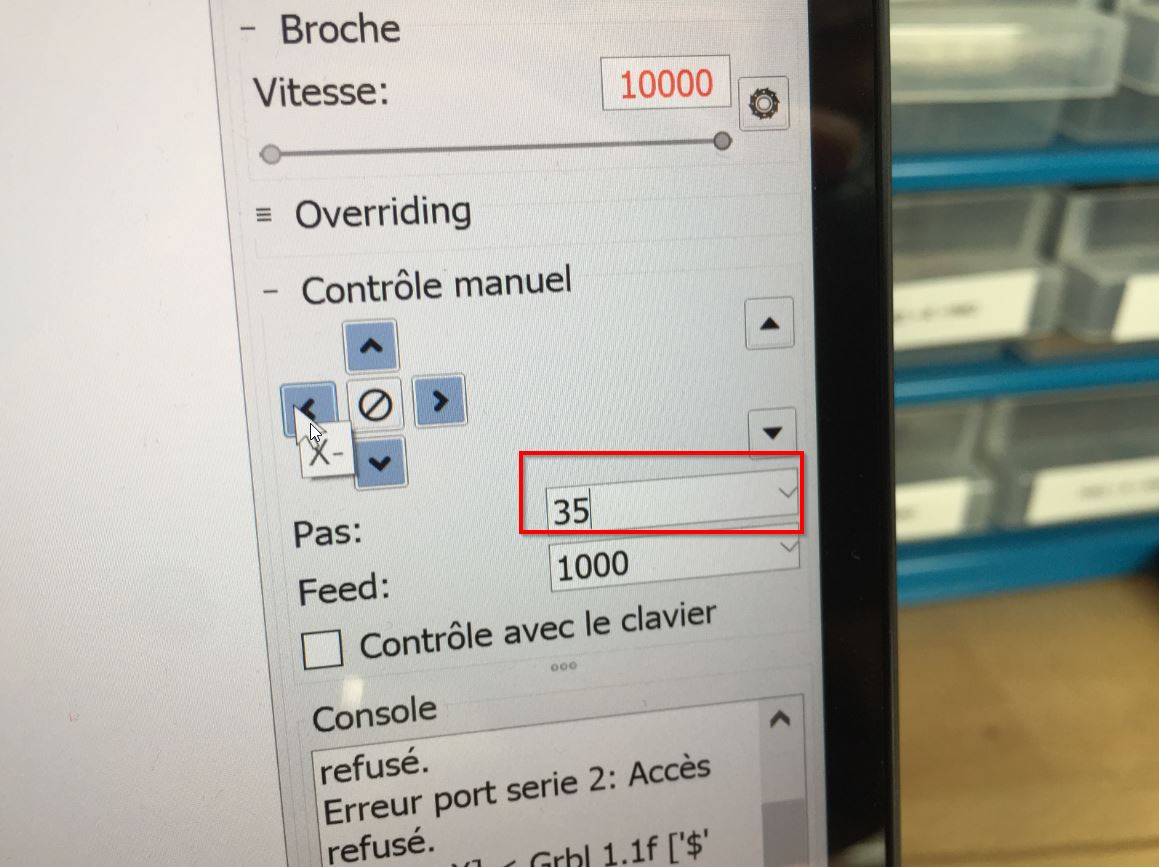
5._2.set X0,Y0 up.
We need to set the Z up.
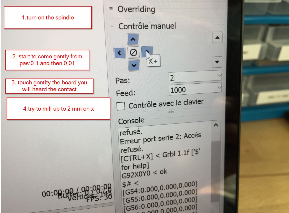 When you are done, check the spindle speed, it is time to go!
You have a 3D visualization of your gcode
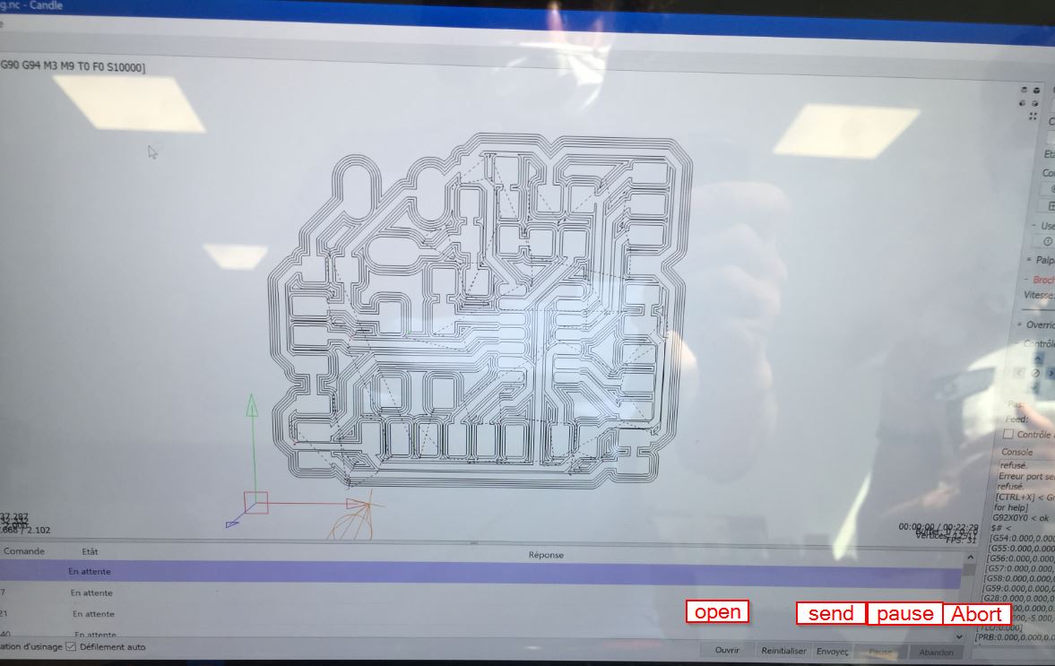
It is milling, do not forget to sweep or to use a vacuum system.
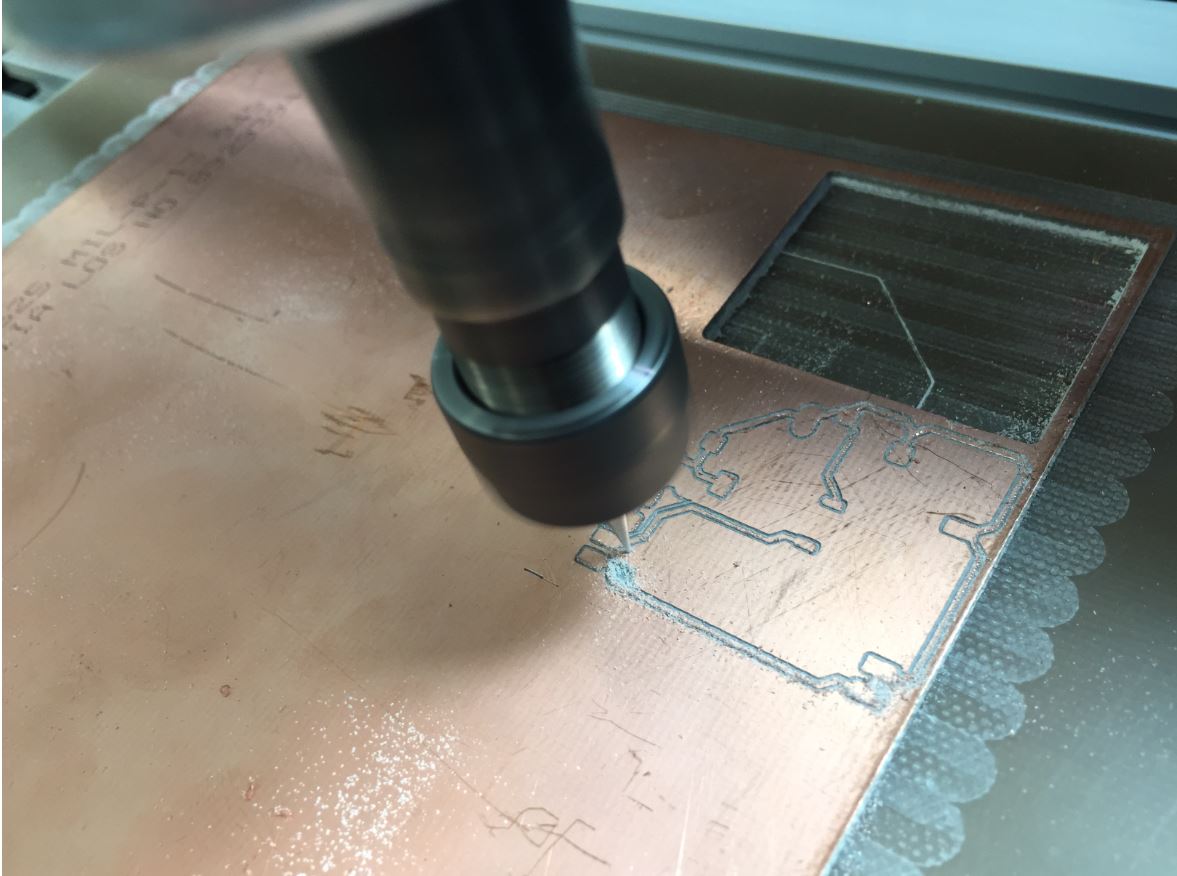
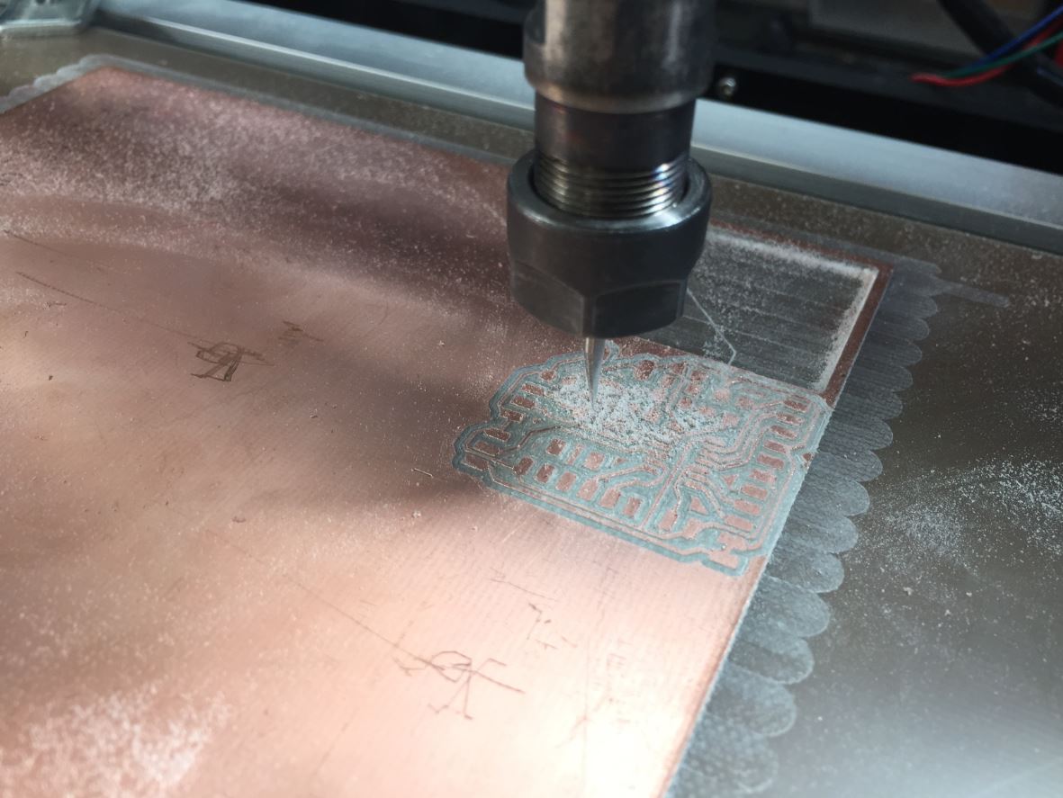
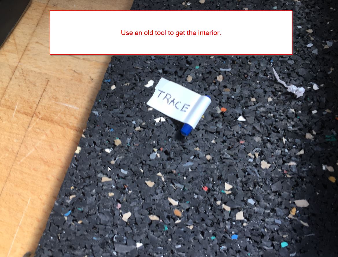
Once it is done, we change the tool to a older one to make the interior.
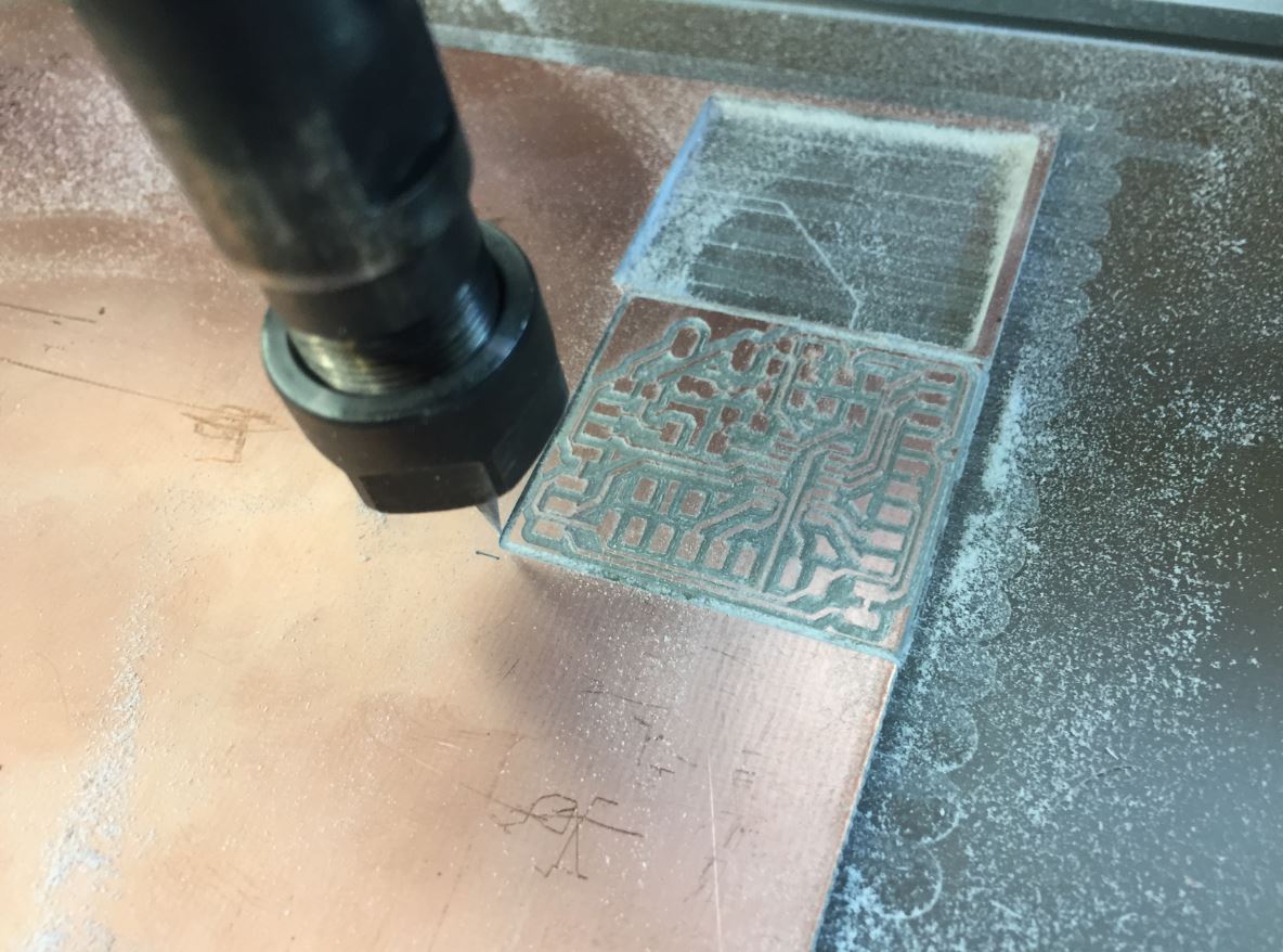
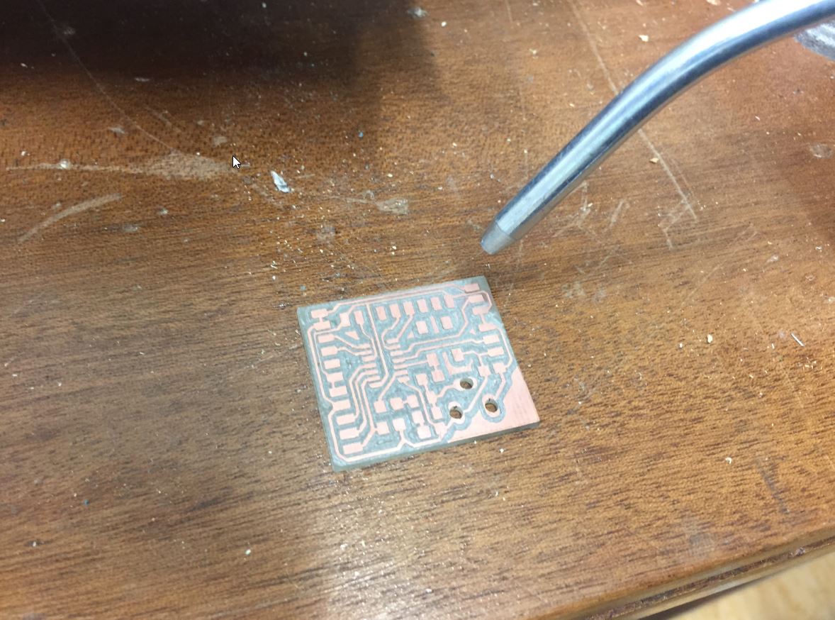
By using a sand paper, I have finished the cnc step.
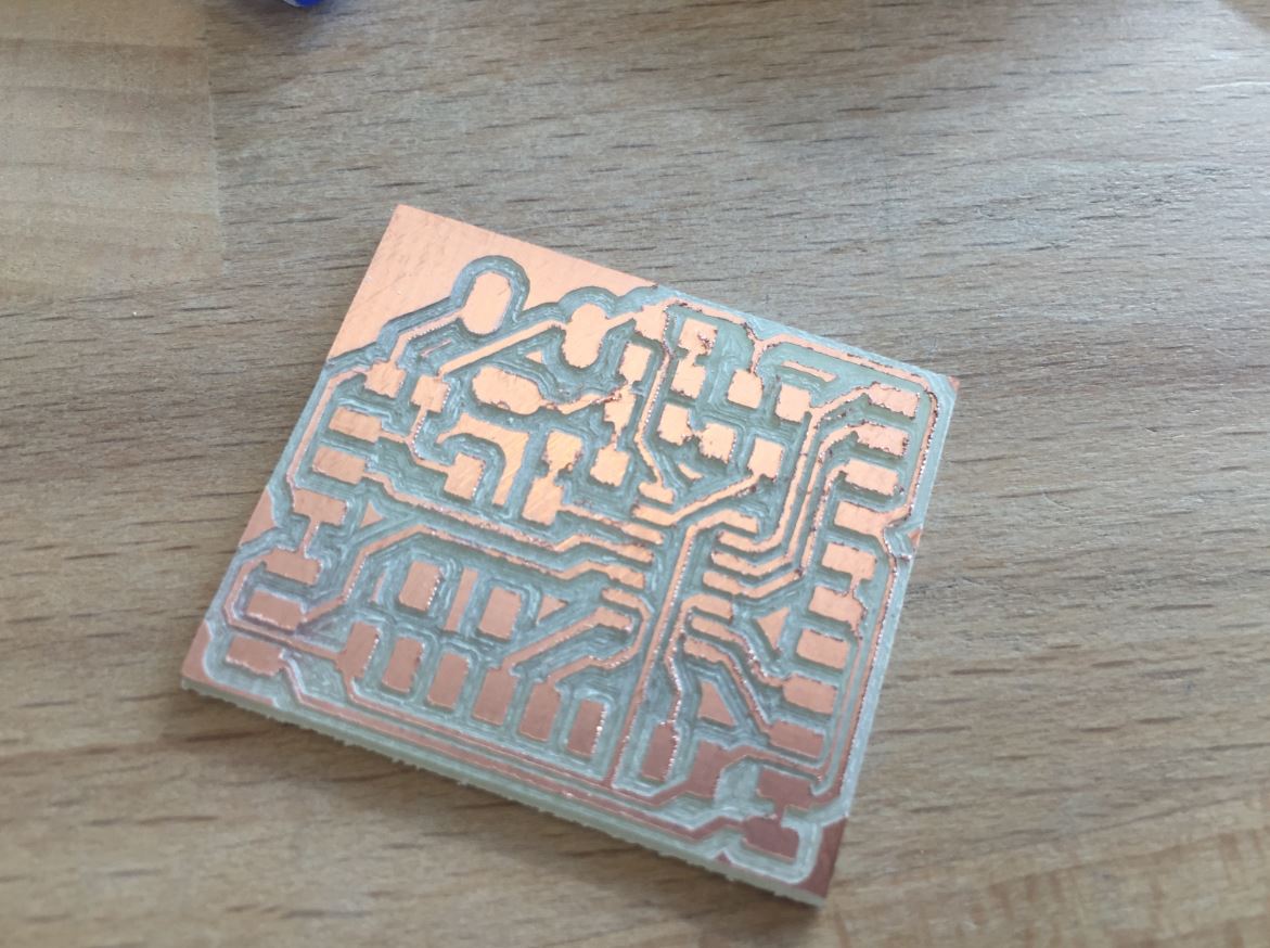
Soldering
For this part, Thierry from Polytech taught me a lot of tricks about soldering. He used to work for the french electronics company: Thomson.
First thing to do is to clean the board. Using a teeth brush and isopropanol.
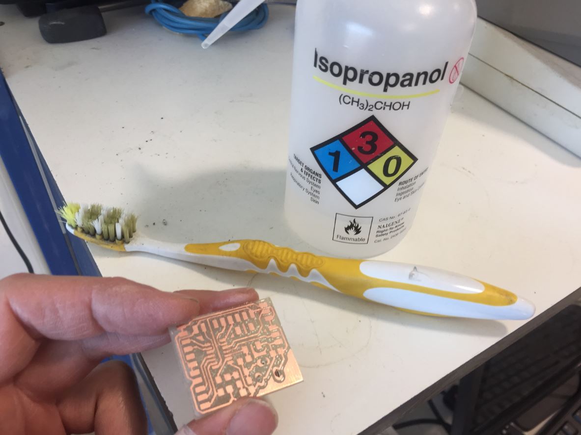
Dry the board.
It is important to clean the iron by using the sponge. Then you start to put pasta(tin+lead) on it. The pasta temperature is about 240°c but 300°c is better.
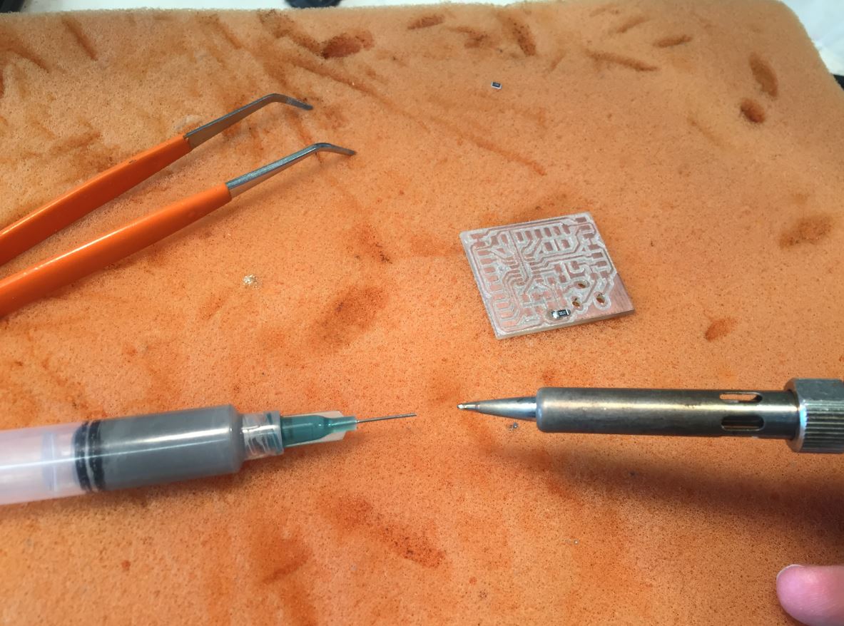
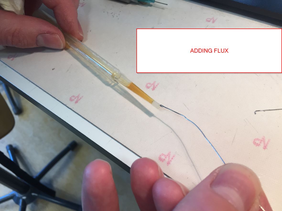
I like to use the syringue, it is very precise!
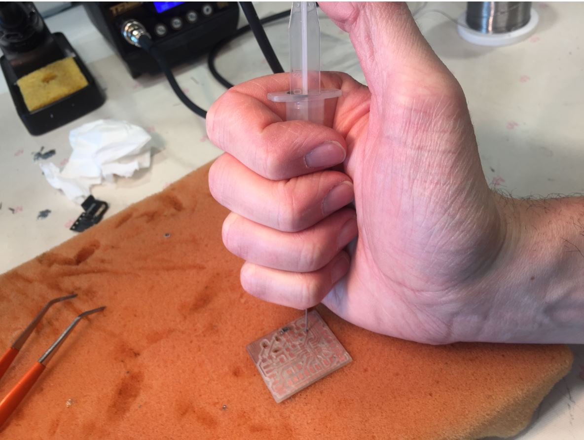
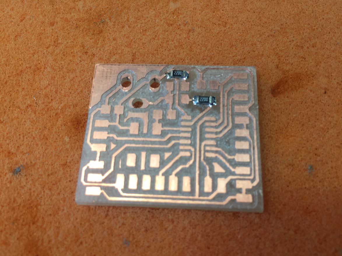
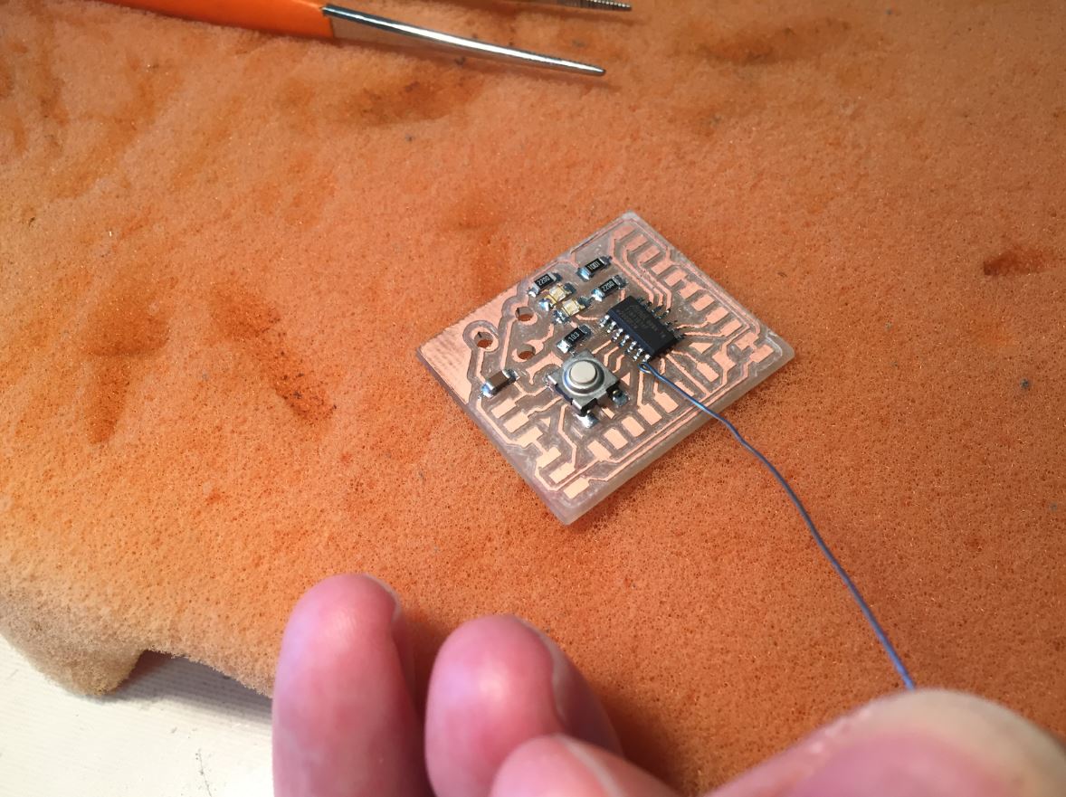
The two first resistors (218ohms) are set up.
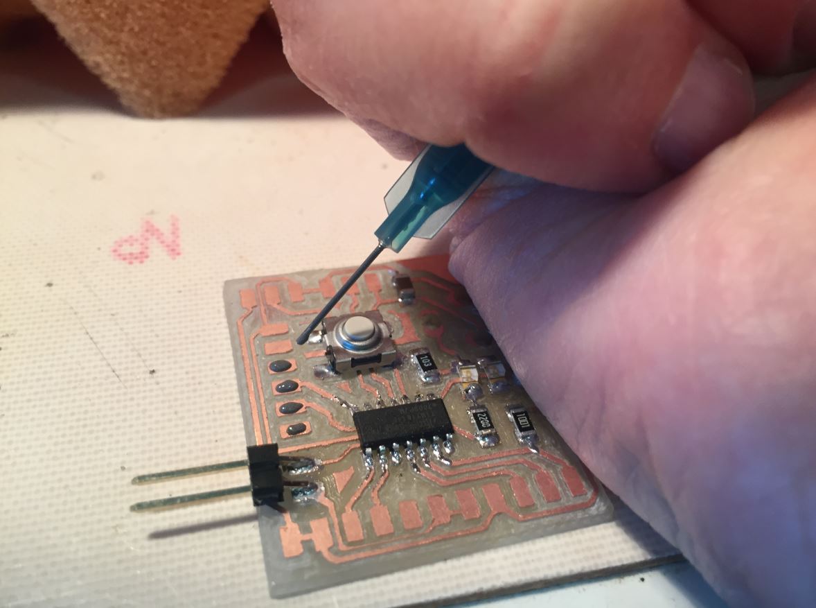
To be flat on the board, do not hesitate to push the component on it and then solder it on one side.
Compared to the soldering wire way , my attiny 1614 is totaly clean according to the syringue way!
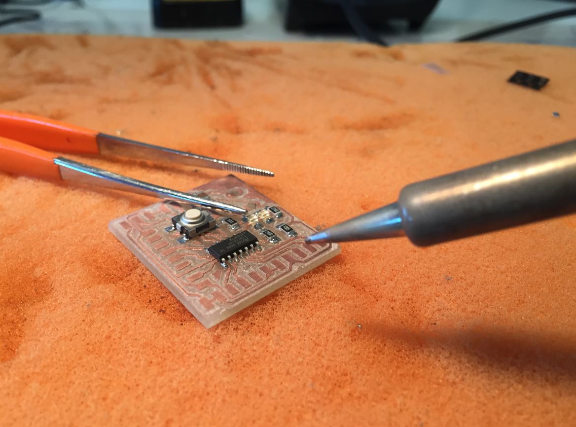
_ I have checked on microscope, and I have some pins not well connected. Thierry advices me to add some flux before re-soldering._
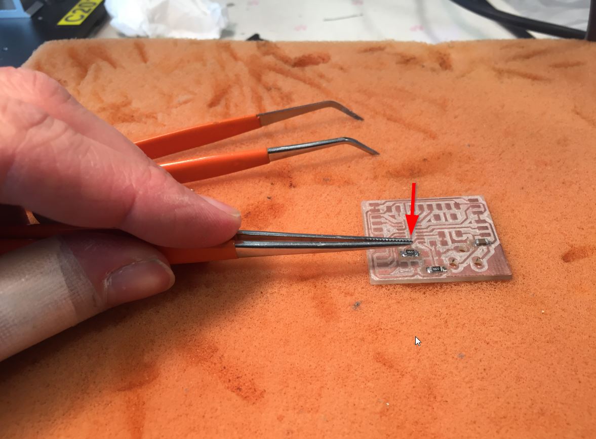
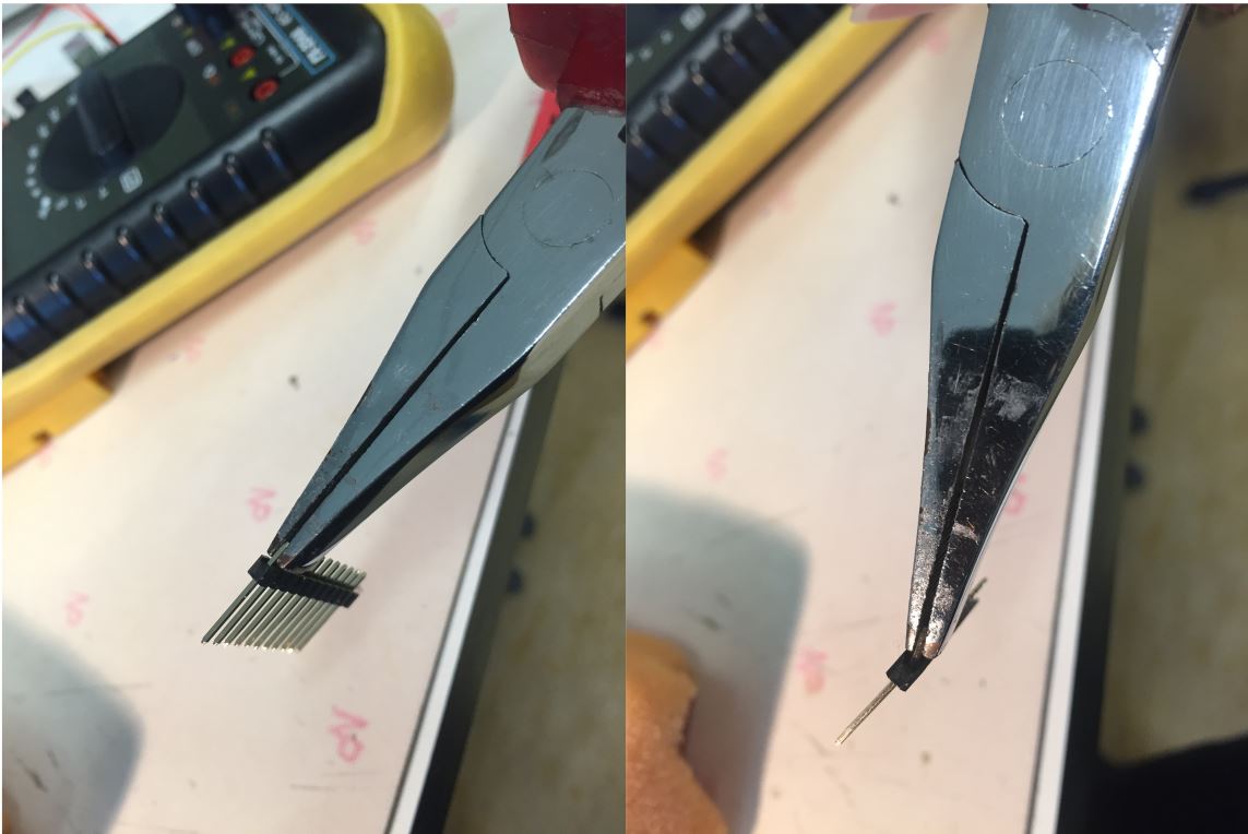
Pins for devices.
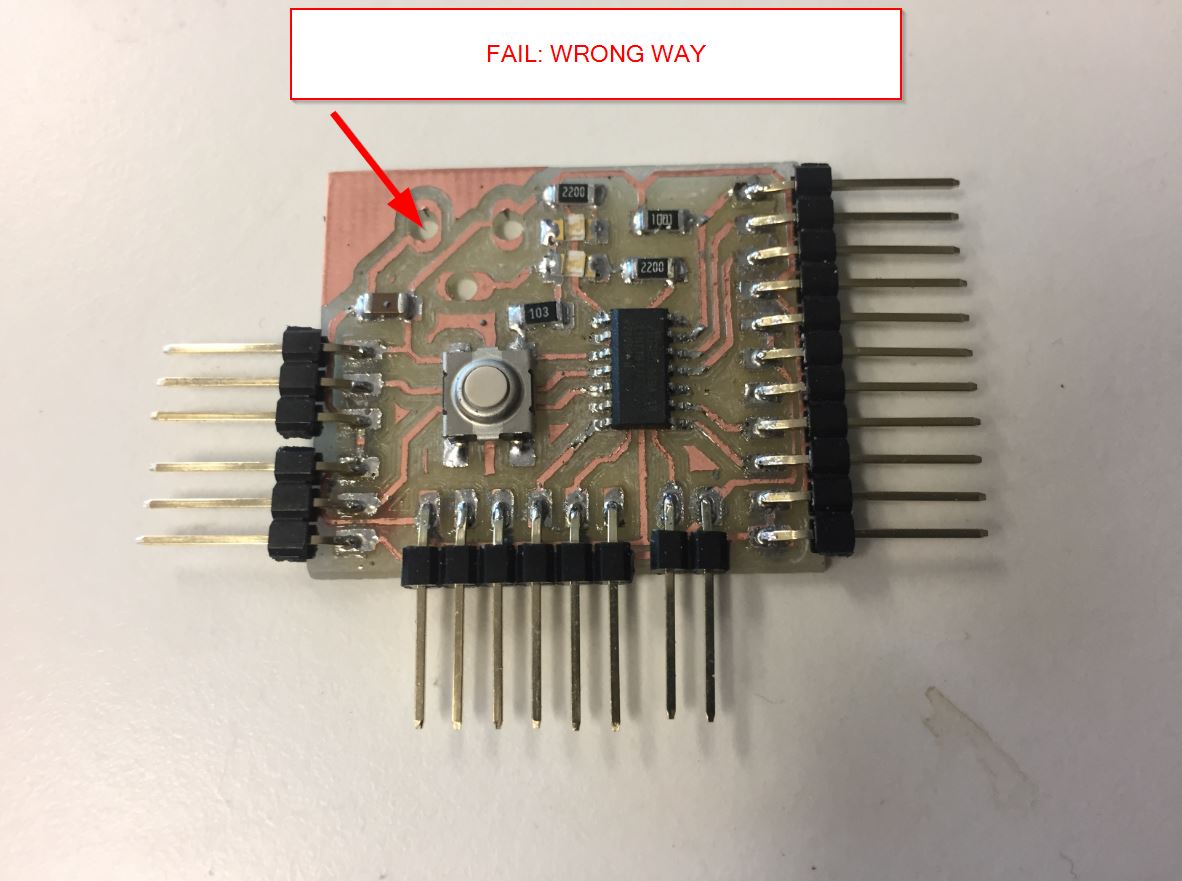
 As the pins are straight, I bent them and adding some glue is a secure way according to Thierry.
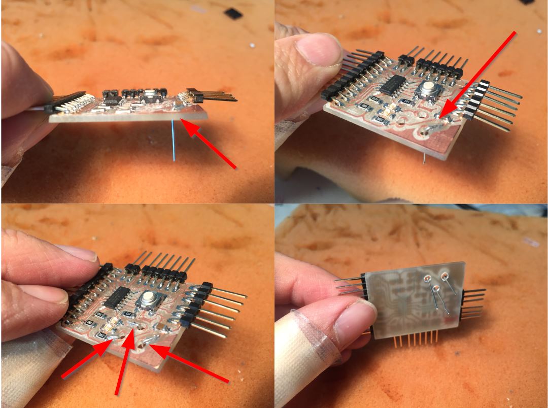
Ok the face of the DC plug is not good… but I do not have much time to finish the assignment.Morever, the ground is split between the two dc pins because I do not have paths to link the ground somewhere on the board.
Thierry advises me to create leads.
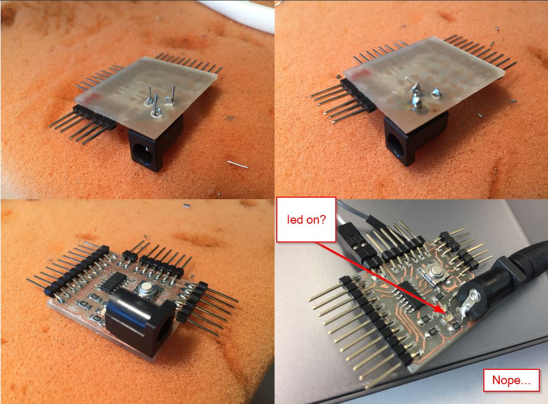
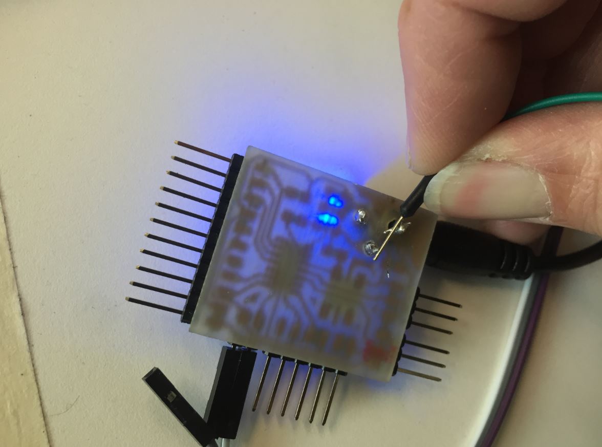
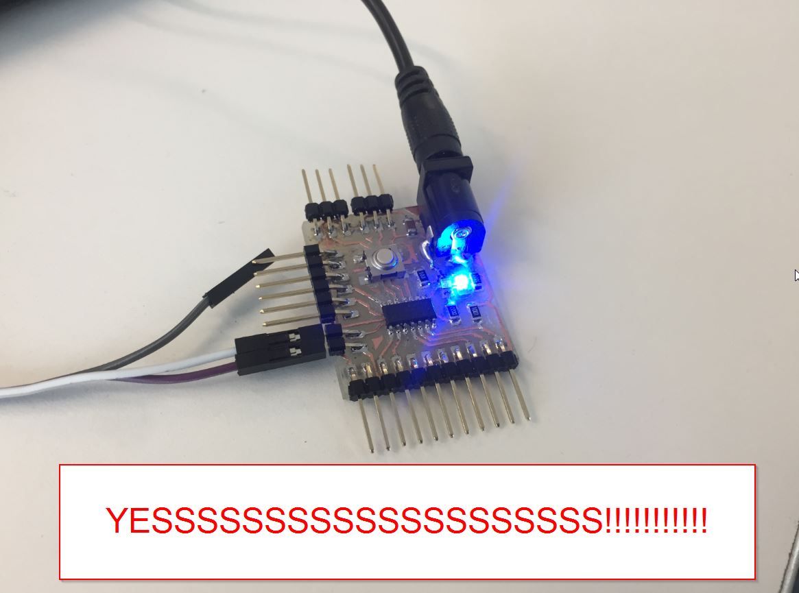
_ When the DC supply is plug on, there is no power led on… Checking on the oscilloscope the voltage, Axel and I found a gnd problem: the switched jack (see above). The only solution is to link the two grounds. _
First we thought that the contact Gnd was no good. But not at all.
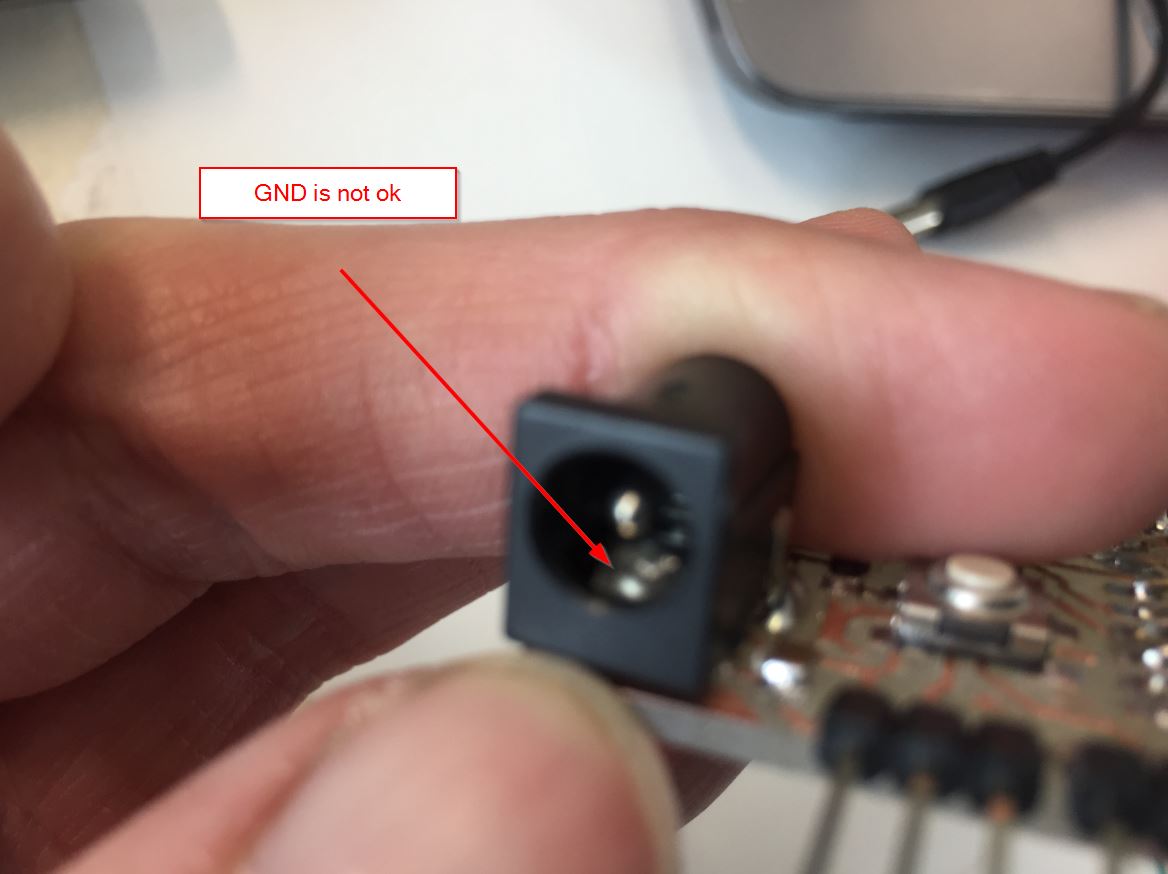
And here comes the light!!!!
Arduino
I am in Polytech so Arthur lended me a ttl programmer.
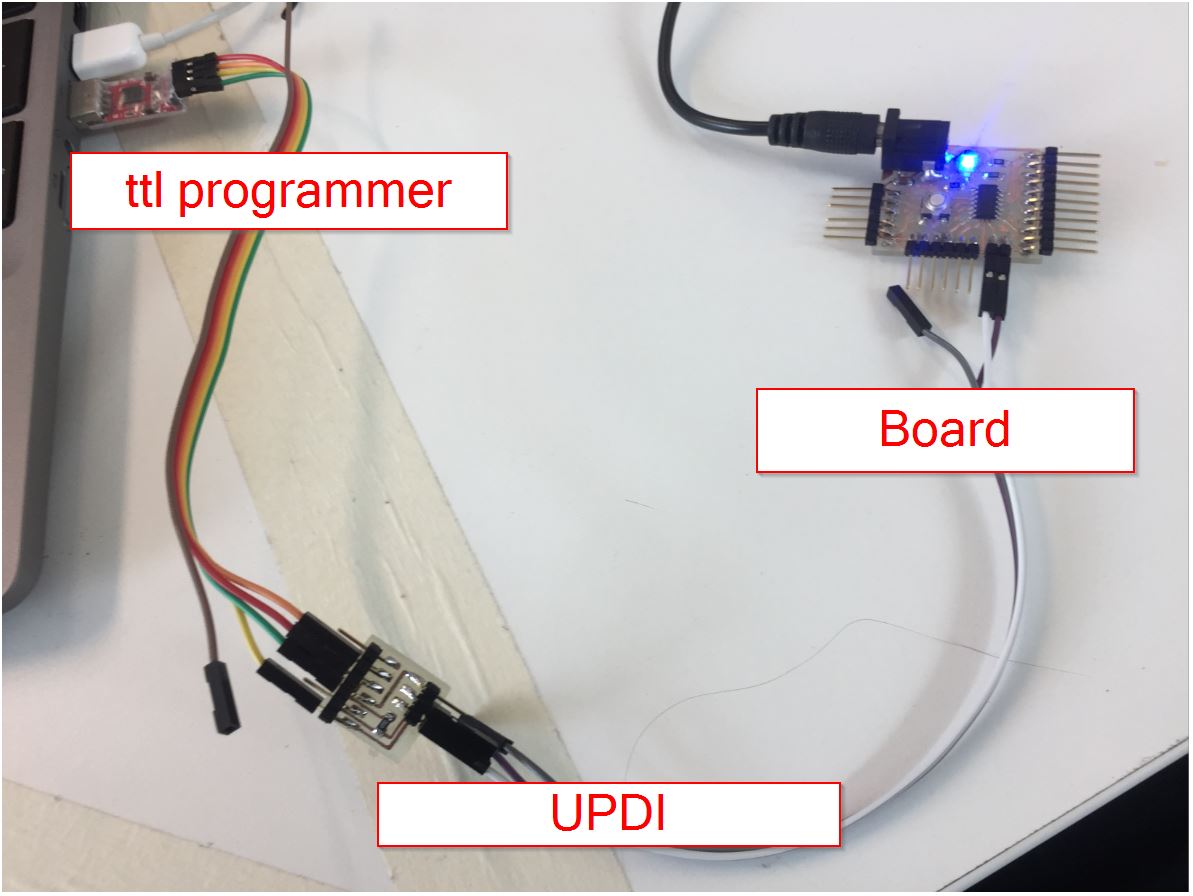
This is a reminder for the UPDI board pinouts.
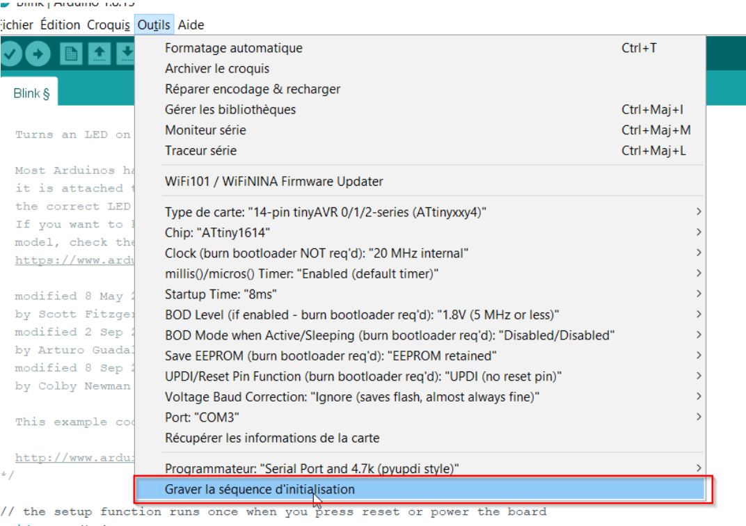
BOOTLOADER
What’s a bootloader? More info on Arduino Microcontrollers are usually programmed through a programmer unless you have a piece of firmware in your microcontroller that allows installing new firmware without the need of an external programmer. This is called a bootloader.
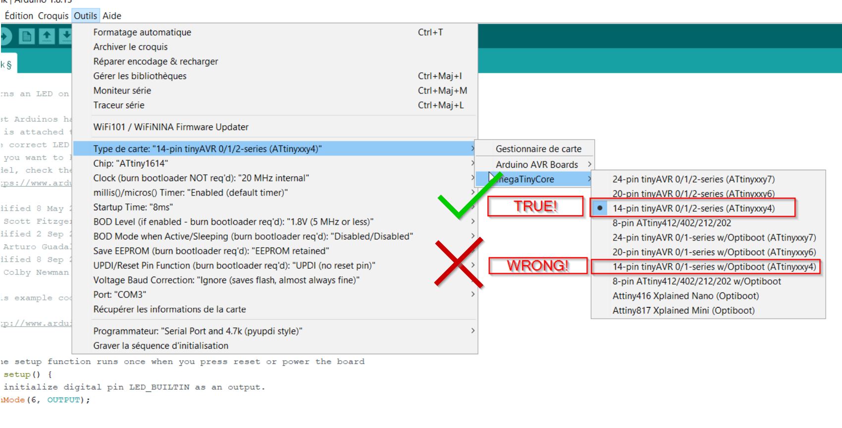
Select the proper MC: ATTINY1614.
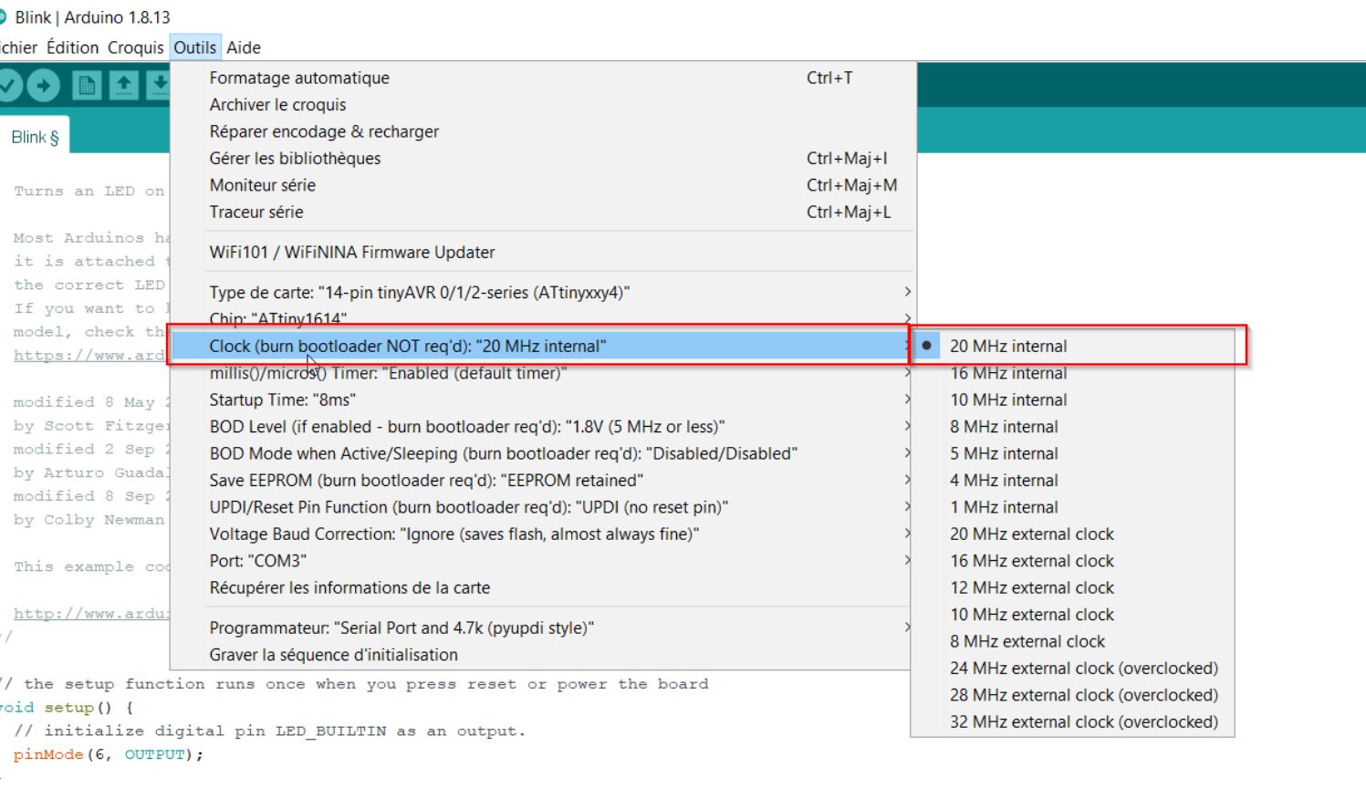
Select the proper clock.
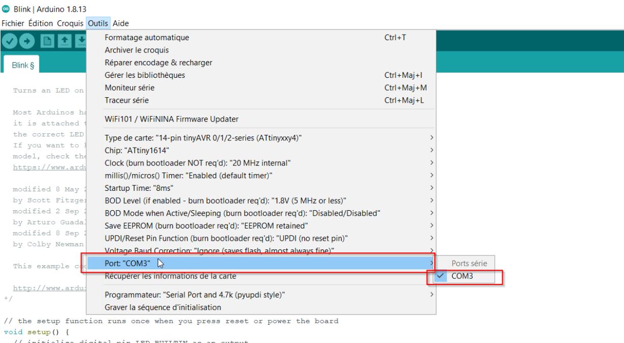
Select the proper port.
Select the proper programmer:
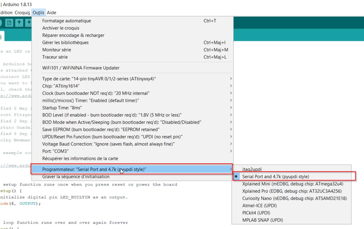
3,2,1… BOOTLOADER!!
Servo:first sketch
Here comes the official page of the Adafruit 16 servo driver: link
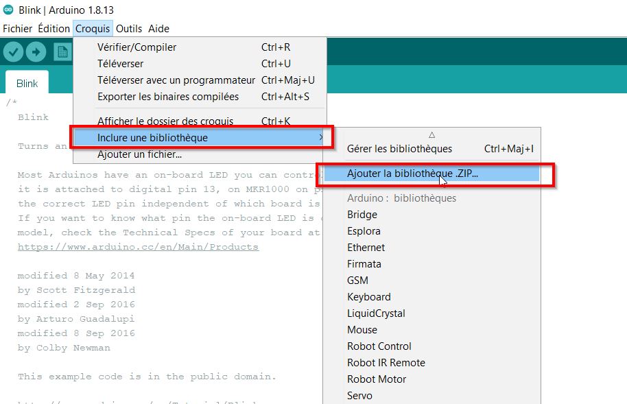
Quickly I upload an example from the servo library.
/***************************************************
  This is an example for our Adafruit 16-channel PWM & Servo driver
  Servo test - this will drive 8 servos, one after the other on the
  first 8 pins of the PCA9685

  Pick one up today in the adafruit shop!
  ------> http://www.adafruit.com/products/815

  These drivers use I2C to communicate, 2 pins are required to
  interface.

  Adafruit invests time and resources providing this open source code,
  please support Adafruit and open-source hardware by purchasing
  products from Adafruit!

  Written by Limor Fried/Ladyada for Adafruit Industries.
  BSD license, all text above must be included in any redistribution
 ****************************************************/

#include <Wire.h>
#include <Adafruit_PWMServoDriver.h>

// called this way, it uses the default address 0x40
Adafruit_PWMServoDriver pwm = Adafruit_PWMServoDriver();
// you can also call it with a different address you want
//Adafruit_PWMServoDriver pwm = Adafruit_PWMServoDriver(0x41);
// you can also call it with a different address and I2C interface
//Adafruit_PWMServoDriver pwm = Adafruit_PWMServoDriver(0x40, Wire);

// Depending on your servo make, the pulse width min and max may vary, you
// want these to be as small/large as possible without hitting the hard stop
// for max range. You'll have to tweak them as necessary to match the servos you
// have!
#define SERVOMIN  150 // This is the 'minimum' pulse length count (out of 4096)
#define SERVOMAX  600 // This is the 'maximum' pulse length count (out of 4096)
#define USMIN  600 // This is the rounded 'minimum' microsecond length based on the minimum pulse of 150
#define USMAX  2400 // This is the rounded 'maximum' microsecond length based on the maximum pulse of 600
#define SERVO_FREQ 50 // Analog servos run at ~50 Hz updates

// our servo # counter
uint8_t servonum = 0;

void setup() {
  Serial.begin(9600);
  Serial.println("8 channel Servo test!");

  pwm.begin();
  /*
   * In theory the internal oscillator (clock) is 25MHz but it really isn't
   * that precise. You can 'calibrate' this by tweaking this number until
   * you get the PWM update frequency you're expecting!
   * The int.osc. for the PCA9685 chip is a range between about 23-27MHz and
   * is used for calculating things like writeMicroseconds()
   * Analog servos run at ~50 Hz updates, It is importaint to use an
   * oscilloscope in setting the int.osc frequency for the I2C PCA9685 chip.
   * 1) Attach the oscilloscope to one of the PWM signal pins and ground on
   *    the I2C PCA9685 chip you are setting the value for.
   * 2) Adjust setOscillatorFrequency() until the PWM update frequency is the
   *    expected value (50Hz for most ESCs)
   * Setting the value here is specific to each individual I2C PCA9685 chip and
   * affects the calculations for the PWM update frequency.
   * Failure to correctly set the int.osc value will cause unexpected PWM results
   */
  pwm.setOscillatorFrequency(27000000);
  pwm.setPWMFreq(SERVO_FREQ);  // Analog servos run at ~50 Hz updates

  delay(10);
}

// You can use this function if you'd like to set the pulse length in seconds
// e.g. setServoPulse(0, 0.001) is a ~1 millisecond pulse width. It's not precise!
void setServoPulse(uint8_t n, double pulse) {
  double pulselength;

  pulselength = 1000000;   // 1,000,000 us per second
  pulselength /= SERVO_FREQ;   // Analog servos run at ~60 Hz updates
  Serial.print(pulselength); Serial.println(" us per period");
  pulselength /= 4096;  // 12 bits of resolution
  Serial.print(pulselength); Serial.println(" us per bit");
  pulse *= 1000000;  // convert input seconds to us
  pulse /= pulselength;
  Serial.println(pulse);
  pwm.setPWM(n, 0, pulse);
}

void loop() {
  // Drive each servo one at a time using setPWM()
  Serial.println(servonum);
  for (uint16_t pulselen = SERVOMIN; pulselen < SERVOMAX; pulselen++) {
    pwm.setPWM(servonum, 0, pulselen);
  }

  delay(500);
  for (uint16_t pulselen = SERVOMAX; pulselen > SERVOMIN; pulselen--) {
    pwm.setPWM(servonum, 0, pulselen);
  }

  delay(500);

  // Drive each servo one at a time using writeMicroseconds(), it's not precise due to calculation rounding!
  // The writeMicroseconds() function is used to mimic the Arduino Servo library writeMicroseconds() behavior.
  for (uint16_t microsec = USMIN; microsec < USMAX; microsec++) {
    pwm.writeMicroseconds(servonum, microsec);
  }

  delay(500);
  for (uint16_t microsec = USMAX; microsec > USMIN; microsec--) {
    pwm.writeMicroseconds(servonum, microsec);
  }

  delay(500);

  servonum++;
  if (servonum > 7) servonum = 0; // Testing the first 8 servo channels
}
 I spent a lot of time to debug the problem. In fact the Adafruit board was out… 1 hour from the review…
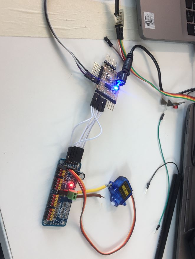
Another board was on my desk, so I soldered and install on my Output board: voilà!!
one moving servo
six moving servos
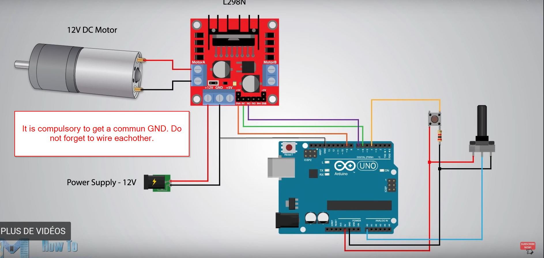
Controlling a 12V motor by using a L298N-driver.
21/04/2023 I would like to drive a motor, because my son and I would like to customize broken RC cars. By watching tutorials, I am following the steps to get my goal. This is the tutorial from How to mechatronics.
How to get a button prepped !! https://docs.arduino.cc/built-in-examples/digital/Button
Let’s discover:
The motor I study is a
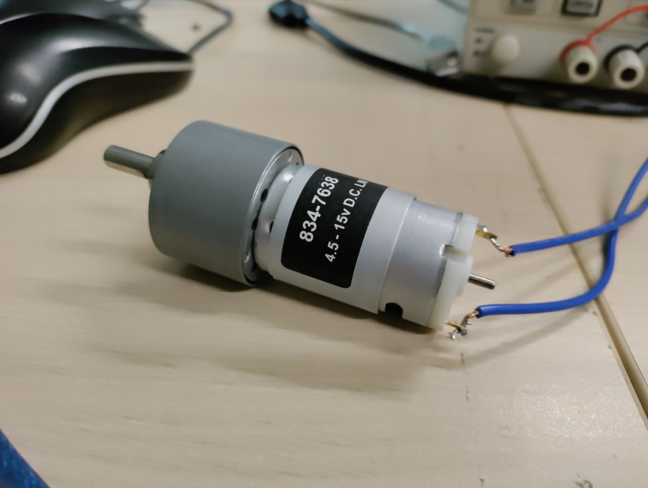
Specifications Supply Voltage = 12 V DC Motor Type = Brushed Geared Power Rating = 7 W Output Speed = 119 rpm Shaft Diameter = 6mm Maximum Output Torque = 29 Ncm Gearhead Type = Spur Dimensions = 27.9 (Dia.) x 92.1 mm Current Rating = 900 mA Length = 70.5mm Width = 37 (Dia.)mm Core Construction = Iron Core
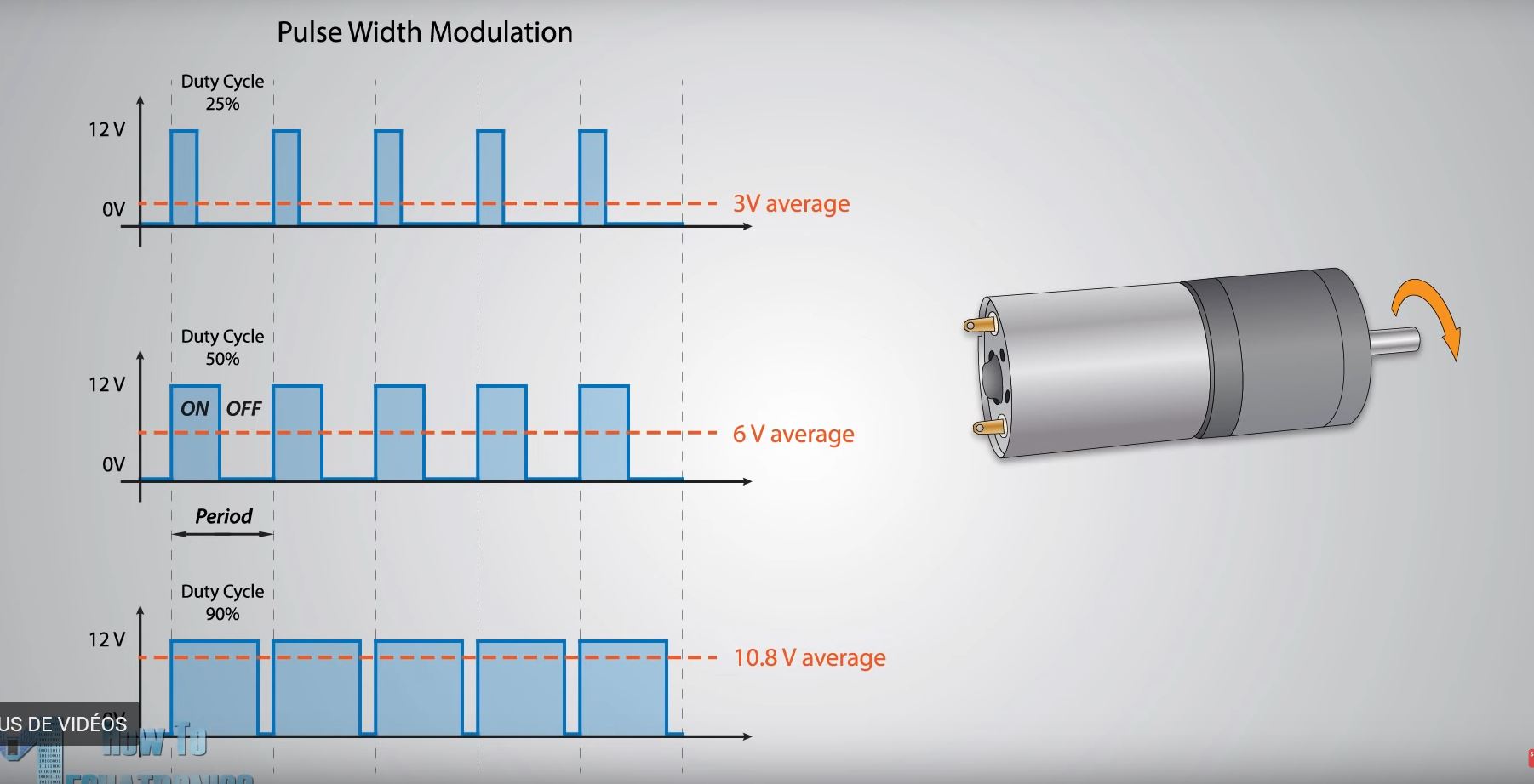
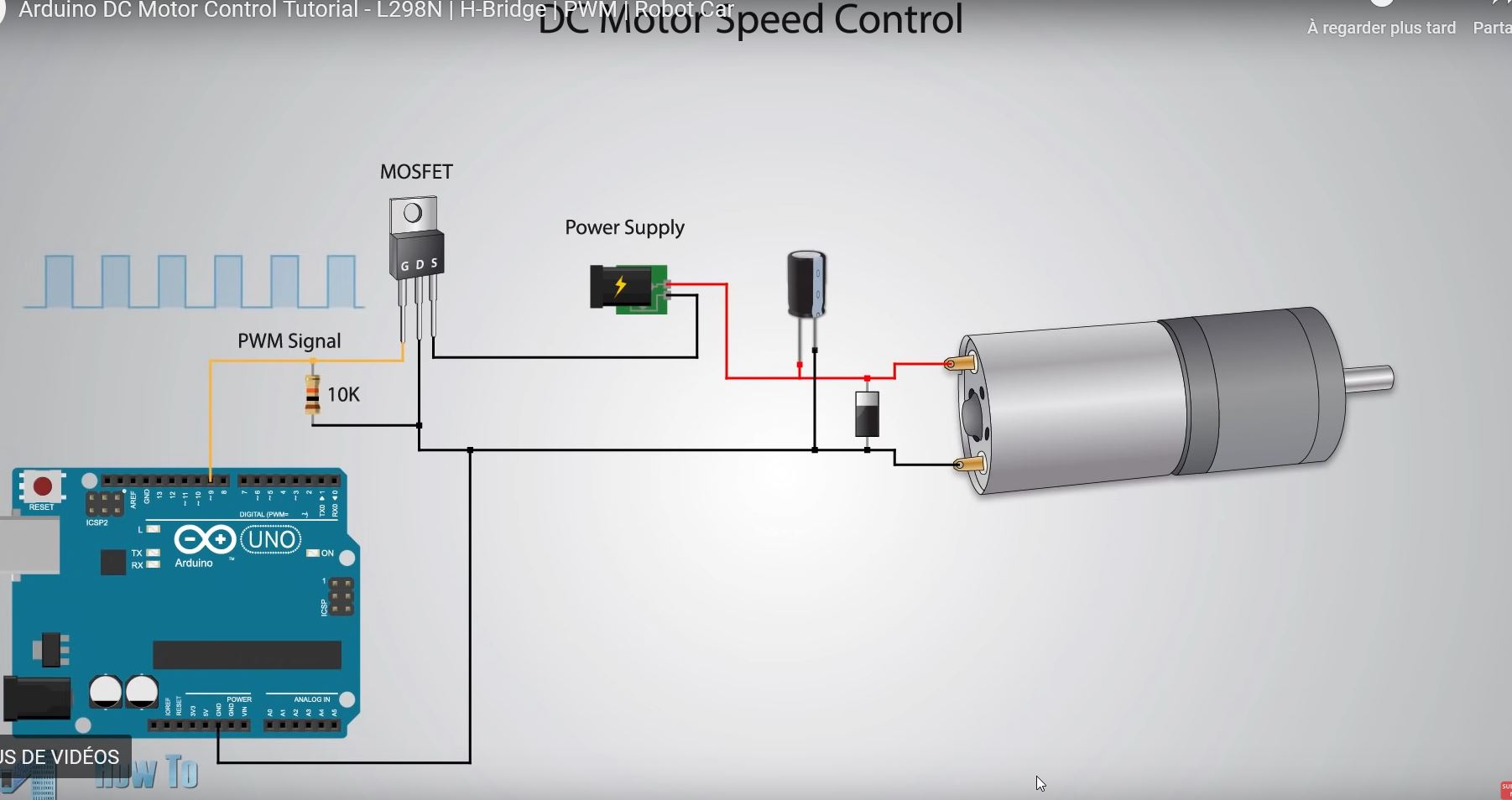
We have PWM pins on arduino board, which let us to control the speed of our motor. According to the time that the 5V signal is coming, the voltage average will give you the level.
To control the motor, we will need a driver, it contains some digital switches in a components called mosfet.
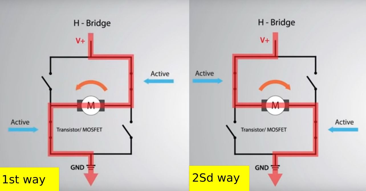
 Here, there are two ways in a H set up.
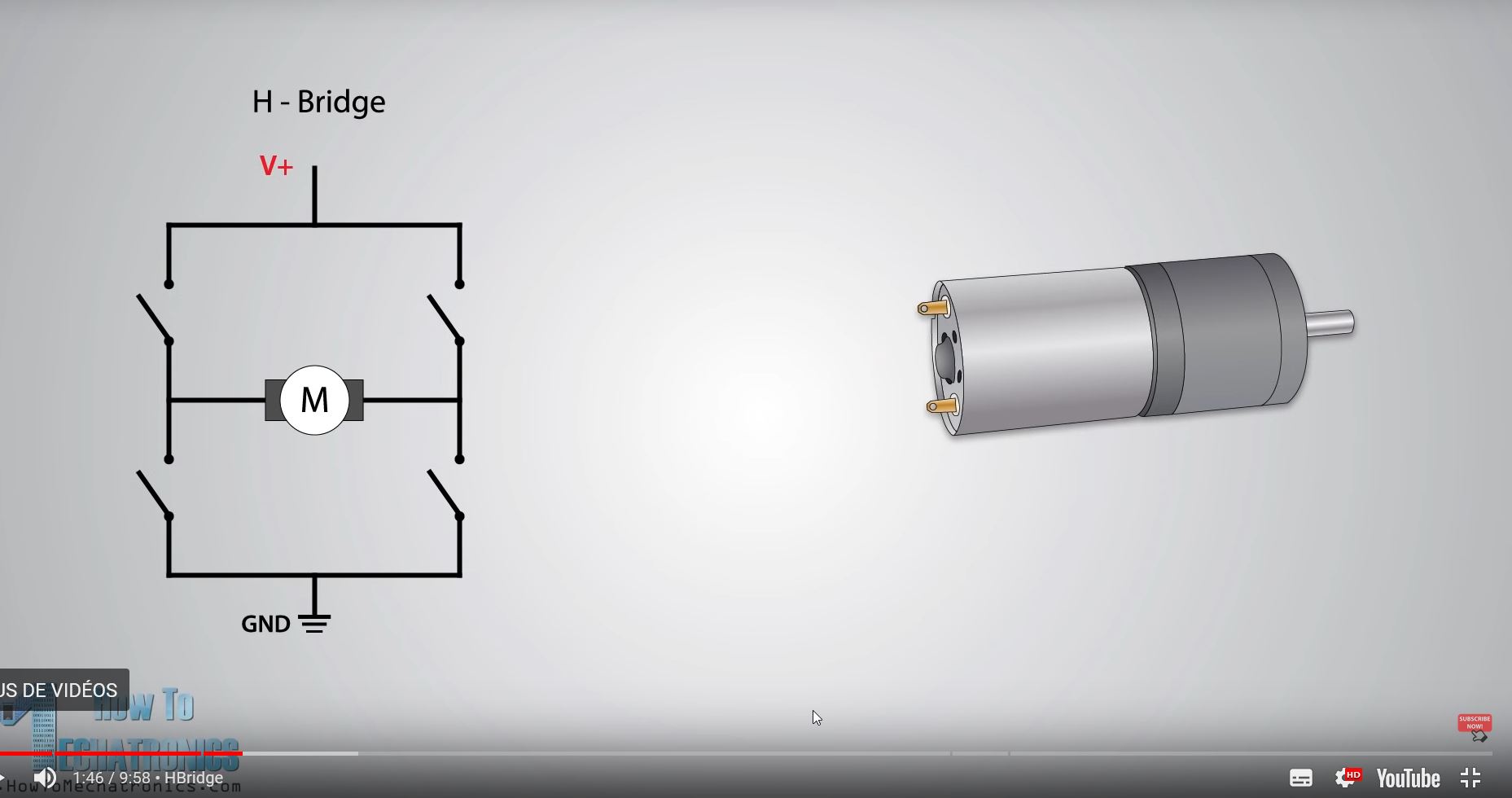
It will let the current go to two ways.
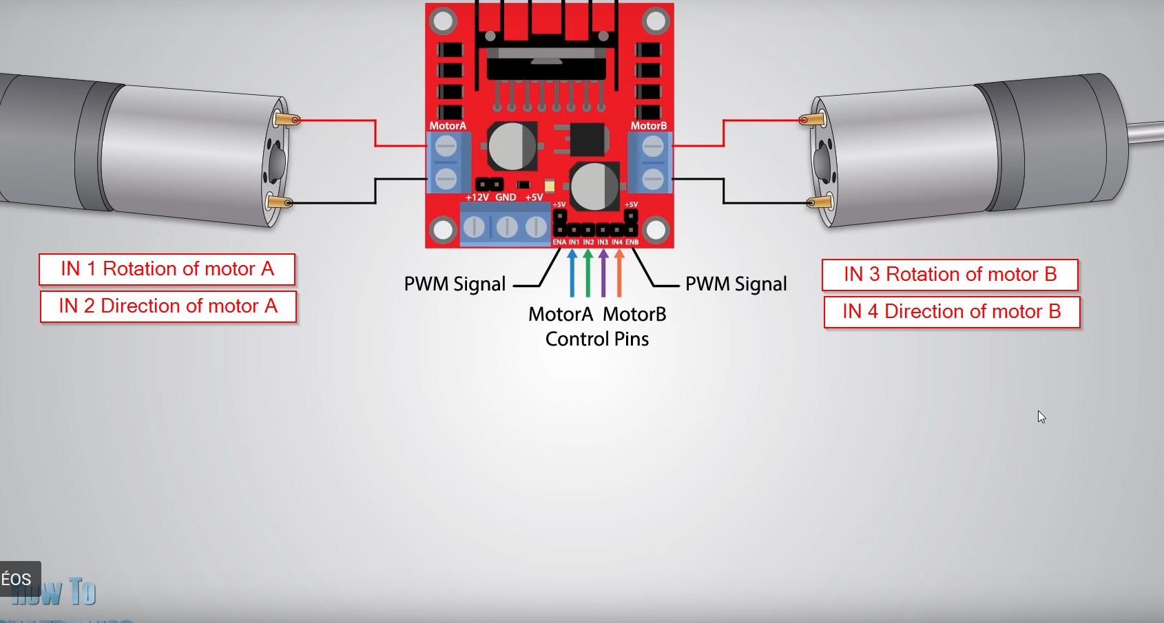
The driver is called : L298N, and have the specs:
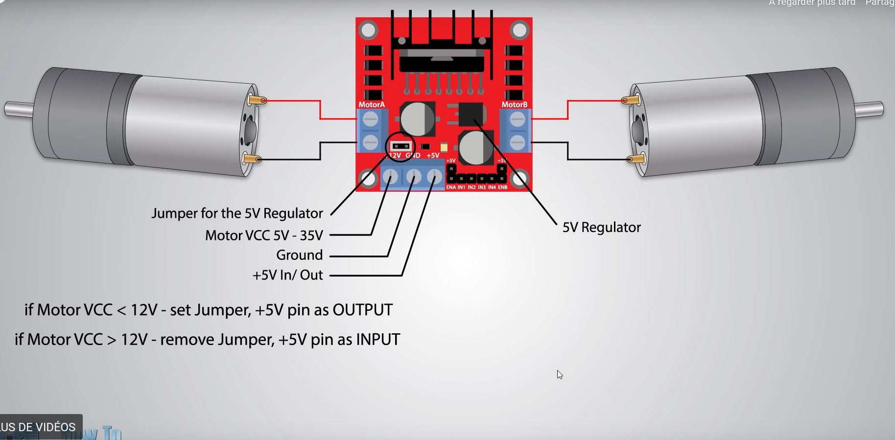
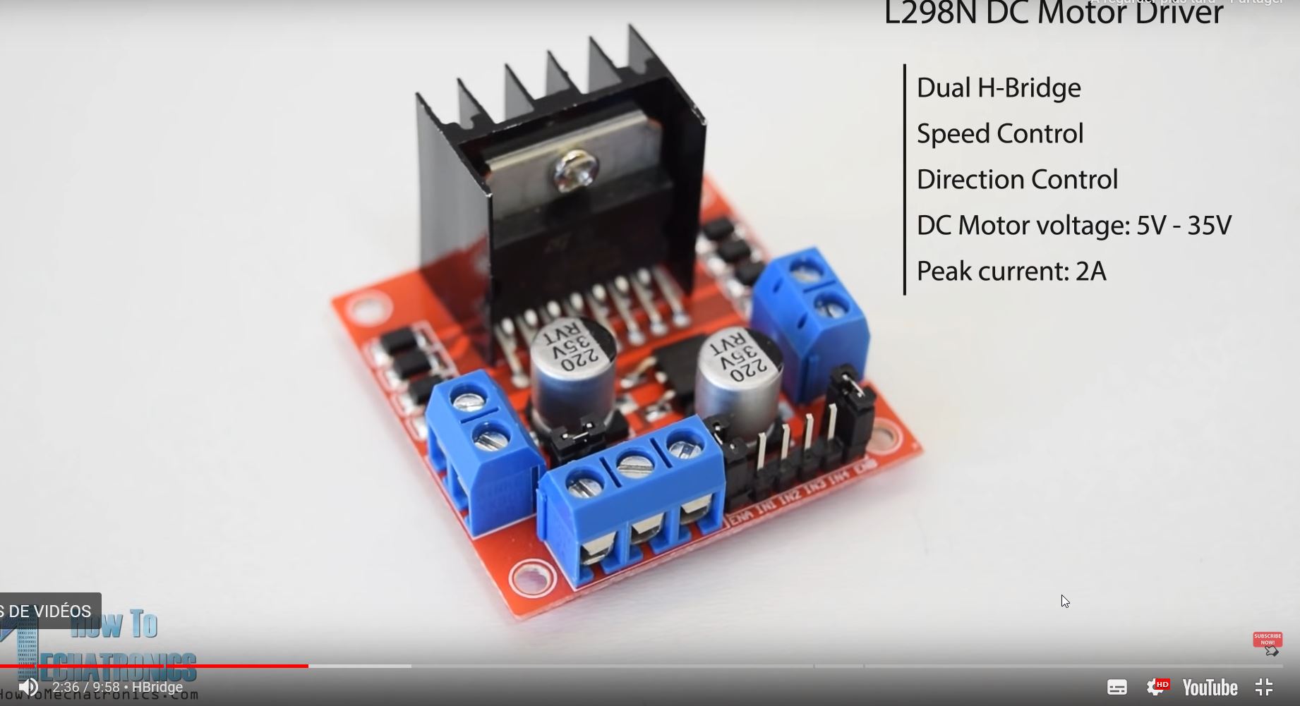 If you set the jumper, you will be able to plug your Arduino board to get the 5V needed.
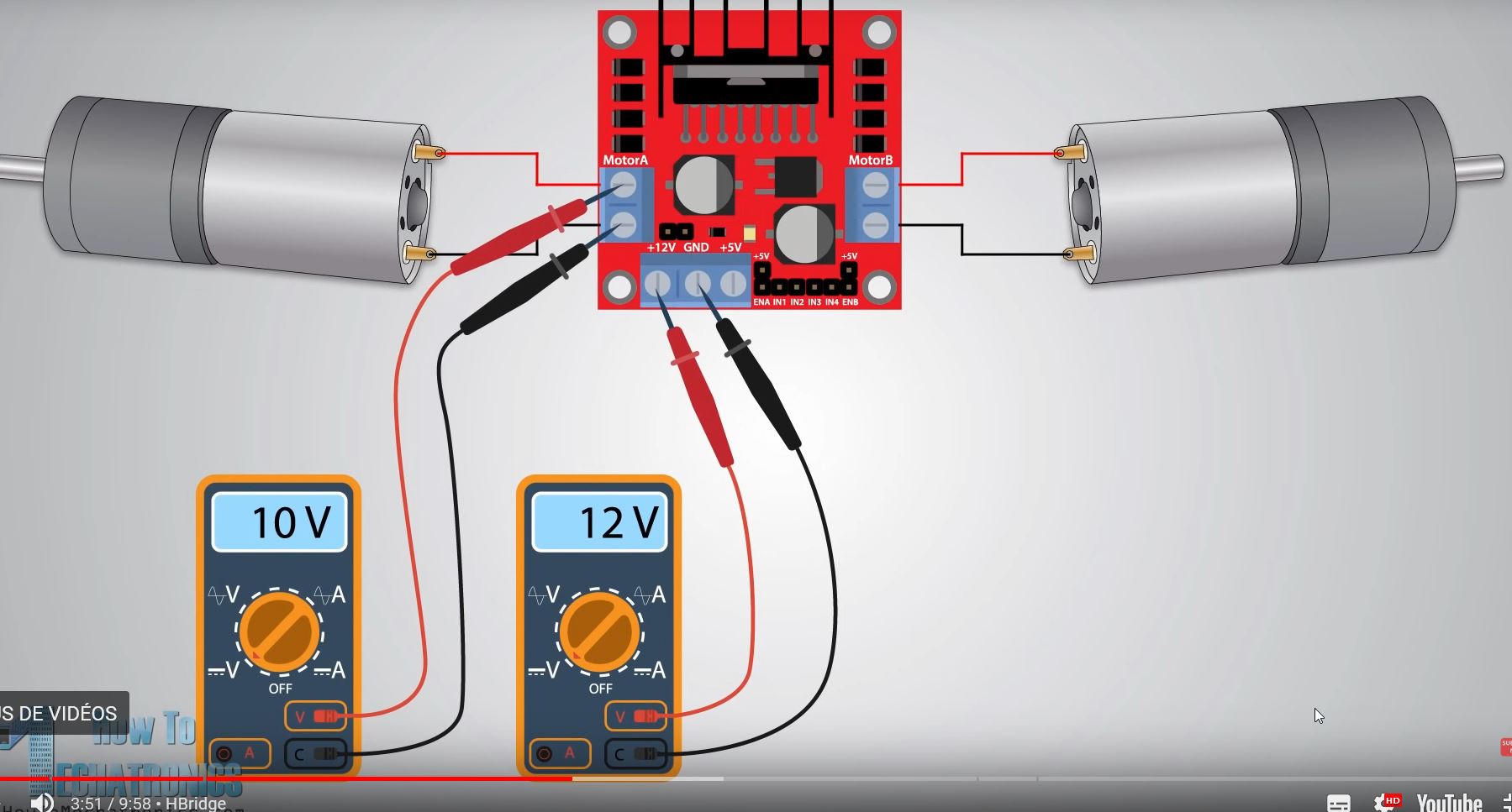
The video mentionned that the 12V delivered will be measured around 10 V. There is a loss of voltage.
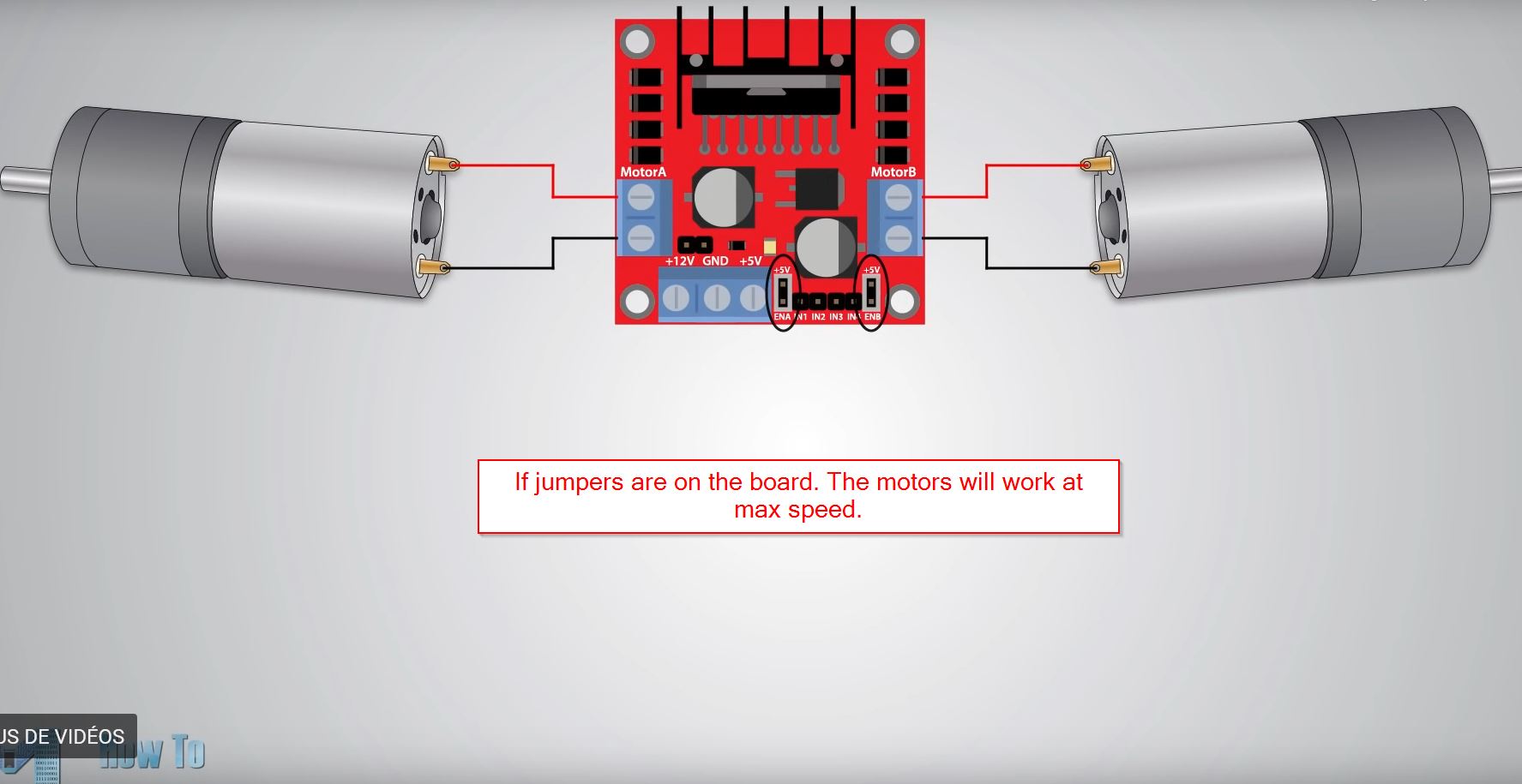
There are jumpers on the driver. If they take place on the board, the max voltage will be given.
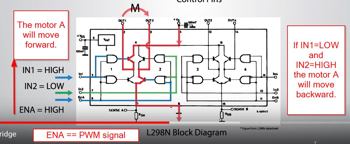
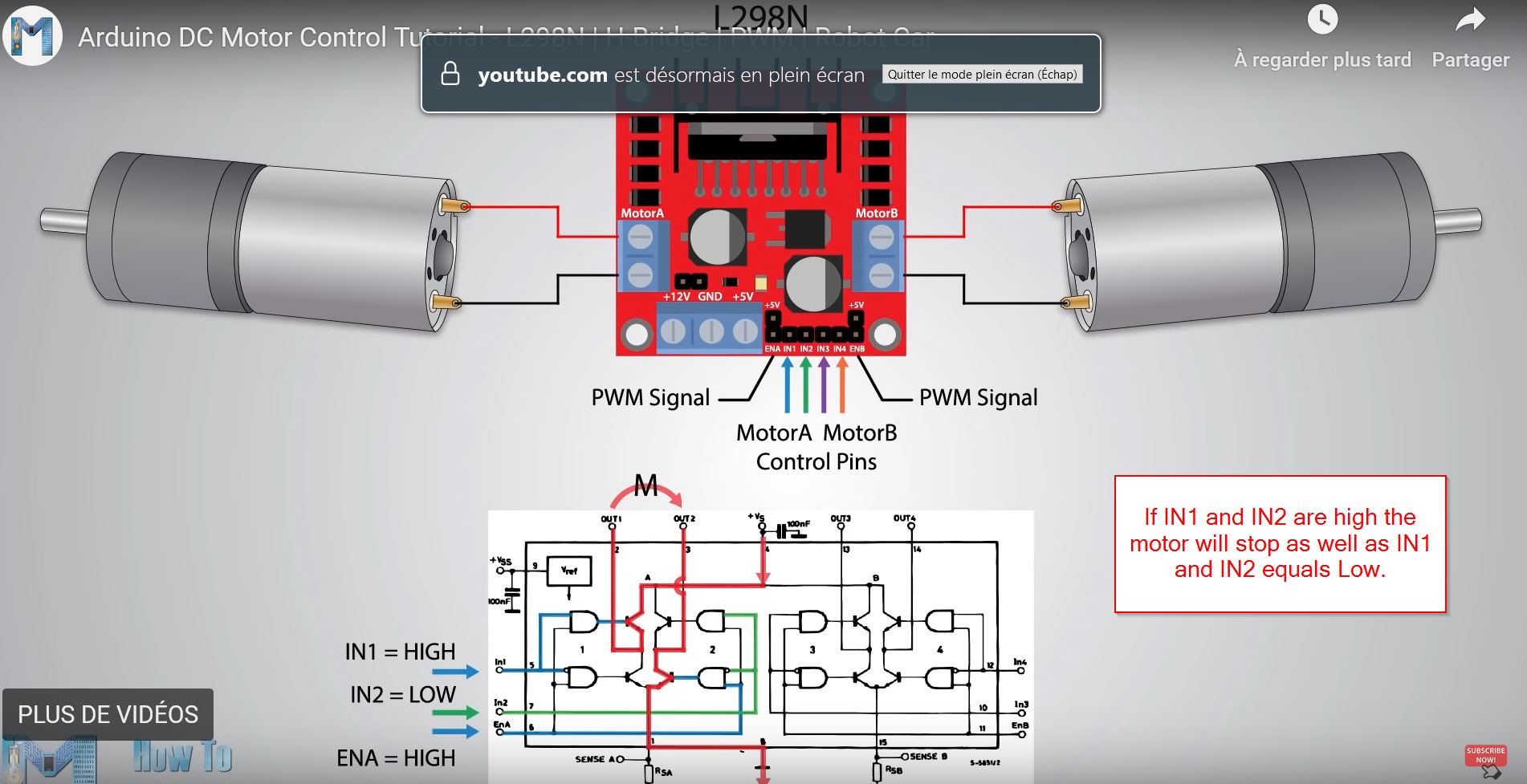
According to each motor, you will have two pins called IN. For example, the left motor has IN1 and IN2. With that, you will have combinations for the C code. IN1 = HIGH // IN2 = LOW // Direction 1 IN1 = LOW // IN2 = HIGH // Direction 2 IN1= HIGH // IN2 = HIGH // STOP IN1 = LOW // IN2 = LOW // STOP
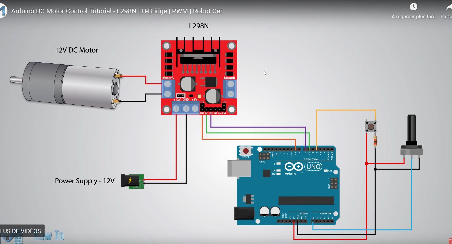
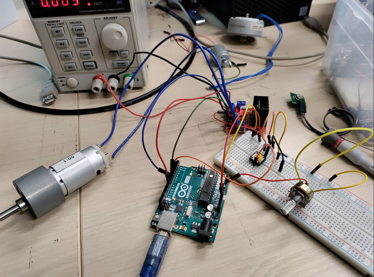
Well, it was not working but IT IS COMPULSORY TO GET A COMMON GND!!!
 VOilà!
#define enA 9
#define in1 6
#define in2 7
#define button 4

boolean buttonstatevoid = LOW;
int rotDirection =0;
int pressed = false;

void setup() {
  // put your setup code here, to run once:
pinMode(enA,OUTPUT);
pinMode(in1, INPUT);
pinMode(in2, INPUT);
pinMode(button, INPUT);
//set initial rotation direction
digitalWrite(in1,LOW);
digitalWrite(in2, HIGH);
}

void loop() {
  // put your main code here, to run repeatedly:
int potValue = analogRead(A0);//read the pot
int pwmOutput = map(potValue,0,1023,0,255); // Map the pot
analogWrite(enA, pwmOutput); // send PWM signal to L298 N enable pin.

//Read button - Debounce anti-rebond
if (digitalRead(button) == true){
  pressed = !pressed; //! is not for boolean
}

while (digitalRead(button) == true);
delay(20);

//if button is pressed - change rotation direction
if(pressed == true & rotDirection == 0) {
  digitalWrite(in1,HIGH);
  digitalWrite(in2, LOW);
  rotDirection =1;
  delay(20);
}
//if button is pressed - change rotation direction
if(pressed == false & rotDirection == 1) {
  digitalWrite(in1, LOW);
  digitalWrite(in2, HIGH);
  rotDirection =0;
  delay(20);
}

}
Download
https://www.homemade-circuits.com/pir-sensor-datasheet-pinout-specification-working/